Fluidic devices and fabrication methods for microfluidics
US20120180882A1
2012-07-19
13/336,717
2011-12-23
✅ Patent granted
US 9,233,369 B2
2016-01-12
-
-
Philip Tucker | Brian R Slawski
Steinfl & Bruno LLP
2034-05-24
Abstract:
A method of fabricating a fluidic device comprises providing a fluidic device including a body having a surface and one or more channels located in the body. Recesses are defined on said surface. The one or more channels can have respective boundaries. A layer of adhesive including one or more panel-shaped pieces having a pattern based on the pattern of boundaries of the channels can be formed and applied on the surface of the body. It is further controlled that the layer of adhesive has respective boundaries surrounding the boundaries of the one or more channels.
Inventors:
- Imran R. MALIK 18 🇺🇸 Pasadena, CA, United States
- Axel SCHERER 17 🇺🇸 Woodstock, VT, United States
Assignee:
- California Institute of Technology 3,514 🇺🇸 Pasadena, CA, United States
Applicant:
Interested in similar patents?
Get notified when new applications in this technology area are published.
Classification:
B01L2200/10 » CPC further
Solutions for specific problems relating to chemical or physical laboratory apparatus Integrating sample preparation and analysis in single entity, e.g. lab-on-a-chip concept
B01L2200/12 » CPC further
Solutions for specific problems relating to chemical or physical laboratory apparatus Specific details about manufacturing devices
B01L2300/0861 » CPC further
Additional constructional details; Geometry, shape and general structure Configuration of multiple channels and/or chambers in a single devices
B01L2300/0887 » CPC further
Additional constructional details; Geometry, shape and general structure Laminated structure
B01L2300/16 » CPC further
Additional constructional details Surface properties and coatings
F03B11/00 IPC
Parts or details not provided for in, or of interest apart from, the preceding groups e.g. wear-protection couplings, between turbine and generator ,
B32B37/12 IPC
Methods or apparatus for laminating, e.g. by curing or by ultrasonic bonding characterised by using adhesives
B01L7/52 » CPC further
Heating or cooling apparatus ; Heat insulating devices with provision for submitting samples to a predetermined sequence of different temperatures, e.g. for treating nucleic acid samples
B01L2200/027 » CPC further
Solutions for specific problems relating to chemical or physical laboratory apparatus; Adapting objects or devices to another; Fluid interfacing between devices or objects, e.g. connectors, inlet details for microfluidic devices
B01L2200/04 » CPC further
Solutions for specific problems relating to chemical or physical laboratory apparatus Exchange or ejection of cartridges, containers or reservoirs
B01L2200/0689 » CPC further
Solutions for specific problems relating to chemical or physical laboratory apparatus; Fluid handling related problems Sealing
B01L2300/0877 » CPC further
Additional constructional details; Geometry, shape and general structure; Configuration of multiple channels and/or chambers in a single devices Flow chambers
B29C65/486 » CPC further
Joining of preformed parts ; Apparatus therefor using adhesives, i.e. using supplementary joining material; solvent bonding characterised by their physical form being non-liquid, e.g. in the form of granules or powders
B32B3/30 » CPC further
Layered products comprising a layer with external or internal discontinuities or unevennesses, or a layer of non-planar form ; Layered products having particular features of form characterised by a particular shape of the outline of the cross-section of a continuous layer; characterised by a layer with cavities or internal voids ; characterised by an apertured layer characterised by a layer formed with recesses or projections, e.g. hollows, grooves, protuberances, ribs
Y10T137/8593 » CPC further
Fluid handling Systems
B32B3/02 » CPC further
Layered products comprising a layer with external or internal discontinuities or unevennesses, or a layer of non-planar form ; Layered products having particular features of form characterised by features of form at particular places, e.g. in edge regions
B01L3/502707 » CPC main
Containers or dishes for laboratory use, e.g. laboratory glassware ; Droppers; Containers for the purpose of retaining a material to be analysed, e.g. test tubes with fluid transport, e.g. in multi-compartment structures by integrated microfluidic structures, i.e. dimensions of channels and chambers are such that surface tension forces are important, e.g. lab-on-a-chip characterised by the manufacture of the container or its components
B01L3/00 IPC
Containers or dishes for laboratory use, e.g. laboratory glassware ; Droppers
B29C65/00 IPC
Joining of preformed parts ; Apparatus therefor
B32B37/00 IPC
Methods or apparatus for making layered products; Treatment of the layers or of the layered products
B32B37/00 IPC
Methods or apparatus for laminating, e.g. by curing or by ultrasonic bonding
B32B38/04 IPC
Ancillary operations in connection with laminating processes Punching, slitting or perforating
B08B7/00 IPC
Cleaning by methods not provided for in a single other subclass or a single group in this subclass
B08B9/02 IPC
Cleaning hollow articles by methods or apparatus specially adapted thereto Cleaning pipes or tubes or systems of pipes or tubes
E03B1/00 IPC
Methods or layout of installations for water supply
F17D3/00 IPC
Arrangements for supervising or controlling working operations
F03B11/02 IPC
Parts or details not provided for in, or of interest apart from, the preceding groups e.g. wear-protection couplings, between turbine and generator , Casings
F15B13/00 IPC
Details of servomotor systems ; Valves for servomotor systems
F16L3/01 IPC
Supports for pipes, cables or protective tubing, e.g. hangers, holders, clamps, cleats, clips, brackets for supporting or guiding the pipes, cables or protective tubing, between relatively movable points, e.g. movable channels
F15C1/06 IPC
Circuit elements having no moving parts; Details, e.g. special constructional devices for circuits with fluid elements, such as resistances, capacitive circuit elements; devices preventing reaction coupling in composite elements ; Switch boards; Programme devices Constructional details; Selection of specified materials Constructional realisation of one single element; Canal shapes; Jet nozzles; Assembling an element with other devices, only if the element forms the main part
B29C65/48 IPC
Joining of preformed parts ; Apparatus therefor using adhesives, i.e. using supplementary joining material; solvent bonding
B01L7/00 IPC
Heating or cooling apparatus ; Heat insulating devices
Description
CROSS REFERENCE TO RELATED APPLICATIONS
The present application claims priority to U.S. Provisional Patent Application 61/426,664 titled “Fabrication Method for Microfluidics with Minimum Adhesive Exposure to Fluids” filed on Dec. 23, 2010, which is herein incorporated by reference in its entirety.
FIELD
The present disclosure relates to fluidic or microfluidic devices and to methods to fabricate microfluidic or fluidic devices.
BACKGROUND
Microfluidic devices and fluidic devices are often attached on supporting substrates or apparatuses. Adhesive bonding has been used extensively but it still remains cumbersome, expensive and time consuming for microfluidic devices and fluidic devices having complex design of channels and reservoirs. Especially when the structures are very small, there is a significant problem of clogging the channels.
SUMMARY
According to a first aspect of the disclosure, a method of fabricating a fluidic device is described, the method comprising: providing a fluidic device including a body having a surface and one or more channels located in the body and defining recesses on said surface, the one or more channels having respective boundaries; forming a layer of adhesive including one or more panel-shaped pieces having a pattern based on the pattern of boundaries of the channels; and applying the layer of adhesive on the surface and controlling the layer of adhesive has respective boundaries surrounding the boundaries of the one or more channels.
According to a second aspect of the present disclosure, a fluidic device is described, the device comprising: a body having a surface and one or more channels located in the body and defining one or more recesses on said surface, the one or more channels having respective boundaries; and a layer of adhesive placed on the surface, wherein the layer of adhesive includes one or more panel-shaped pieces having a pattern which is based on the pattern of boundaries of the one or more recesses.
Further aspects of the disclosure are shown in the specification, drawings, and claims of the present application.
BRIEF DESCRIPTION OF THE DRAWINGS
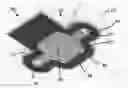
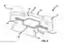
FIG. 1 shows a perspective view of an exemplary fluidic device.
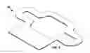
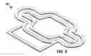
FIG. 2 shows a layer of adhesive according to an aspect of the present disclosure.
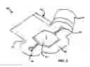
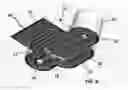
FIG. 3 shows a perspective view of a fluidic device according to an embodiment of the present disclosure.
FIG. 4 shows a perspective view of a fluidic device according to an embodiment of the present disclosure.
FIG. 5 shows a layer of adhesive according to an aspect of the present disclosure.
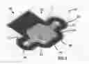
FIG. 6 shows a perspective view of a fluidic device according to an embodiment of the present disclosure.
DETAILED DESCRIPTION
With reference to the enclosed figures, a microfluidic device (10), or microchip, for example a diagnostic cartridge, can include a main solid body or block (12). The block (12) can include a flat surface (16) and two fluid inlet or outlet ports (17), which can be located on a first side (19) of the block (12). On the flat surface (16), e.g., on an exposed surface of the block (12), the microfluidic device (10) can include fluid channels (13), (14), (15), and more in particular, two end channels (13), (15), which can be partially embedded in the flat surface (16) and partially embedded in the ports (17), and a reservoir/cavity (14), which can be located between and fluidly connected to the two end channels (13) (15). The reservoir (14) can be defined with the two end channels (13) (15), and more in particular with respective inlet mouths of the channels (13) (15), open recesses or cavities on the external surface (16), having respective boundaries.
According to an aspect of the present disclosure, the microfluidic device (10) can include a layer of adhesive (30), which can be structurally independent from the block (12) and can be applied on the external surface (16). The layer of adhesive (30) can be designed a priori based on the design of the channels of the body (12). In particular, the layer of adhesive (30) can include one or more panel-shaped pieces having a pattern (with respective boundaries) which can match, correspond or be based on the pattern of boundaries of the channels or cavities of the external surface (16). In other words, the layer of adhesive (30) can include one or more thin structures matching with the boundaries of the channels, without clogging the channels. The adhesive can be applied in various ways known to those having ordinary skill in the art. In the shown examples, the layer of adhesive includes one or more substantially annular-shaped flat pieces.
In particular, a very thin layer of adhesive, previously designed, can be deposited on the exposed surface (16). FIGS. 1-6 show possible plate patterns for application of adhesive and respective layers of adhesive. The adhesive can be applied on flat metal plate, separated from the cartridge/block (12) or on a plastic part. Eventually different surfaces of the fluidic device can be bonded to the substrates by the same technique and by changing adhesives if needed. The adhesive thickness can vary (e.g., few microns thick).
According to further aspects of the present disclosure, almost no adhesive (30) comes in direct contact with fluid passing through the channels (13), (14) and (15). In many cases, it can decouple adhesive chemical compatibility from the fluids in the microfluidic devices. This can be achieved from making very fine protrusions (24) (for example, few microns in some cases or less) which can protrude from the surface (16). Such structures can be readily made using various techniques including injection molding. FIG. 4 shows a fluidic device including the protrusions (24). Applying adhesive (using pad printing or otherwise like from a dispensing robot) to outside of protrusion (24) allows bonding of the cartridge while not allowing any/minimum interaction of fluid and the adhesive. In other words, according to a further aspects of the present disclosure, in order to delimit and confine the layer of adhesive (30), the external surface (16) of the block (12) can have etched or depressed regions (22) made around the end channels (13) (15) and/or the reservoir (14). Such etched regions can define respective protruding walls or protrusions (24) which protrude from the external surface (16) and can be located along the end channels (13) (15) and/or the reservoir (14). The etched or depressed regions (22) are able to receive or accommodate or house a layer of adhesive (30) and have pattern corresponding to the pattern of the layer of adhesive (30).
According to further embodiments of the present disclosure, the layer of adhesive (30) can be cut or deposited in such a manner that a small offset can be left between boundaries of channels (13) (14) and (15) and the pattern of the layer of adhesive (30). In particular, after deposition of the adhesive, a pressure can be applied on the adhesive to obtain the layer. An amount of adhesive can be previously accurately calculated to obtain said small offset and a defined thickness of the adhesive. Application of pressure can allow small flow of adhesive but it can stop due to fluidic effects and could form very sharp and well defined boundary mating with channel and reservoir boundaries. In some cases a very slight pressure might be needed due to the already thin layer of adhesive. This process can be very fast, economical and repeatable. While many other techniques to apply adhesive can fill the whole space except for the areas where fluids are to be moved, this methods of the present disclosure can allow controlled modifications of the adhesive so that channels are sealed without clogging, while minimizing use of adhesive supplies.
With reference to FIG. 6, a cartridge according to a further embodiment of the present disclosure is shown. The cartridge of FIG. 6 includes a layer of adhesive (30) which can partially overlap the external surface (16) and provide selective bonding regions. In particular, such application can allow thermal guards to be automatically built in microfluidic structures (e.g., PCR reactors). In fact, air can be trapped in between adhesive layers and can then act as an insulator so that heat transfer in lateral dimension along adhesive is reduced.
For example, one can use the same technique for application of thermal or other epoxy on a large area with less thickness. Thus thermal epoxy using this technique to bond metal plate bottom with polymer (for example kapton) backed heater for qPCR can be applied. Also for two part epoxies, one can have a two color pad printing style application in which the areas of application overlap. Due to very small thickness, the mixing should be sufficient for mixing and curing. UV adhesives can also be used as well as many other kinds.
According to further aspects of the present disclosure, a method to create adhesive layers is disclosed. In particular, adhesive of various viscosities can be applied using dispensers, robots, pad printing, screen printing and other techniques, to obtain an adhesive layer. The obtained layer can be non-uniform due to surface tension and other effects. By applying a known pressure, the adhesive (which can flow) can make a uniform layer. The layers can automatically form a pattern due to fluidic physics. The thin adhesive layer reaches the boundary. This makes deposition of thin layers on large substrates extremely efficient, low cost and quick. Therefore, according to an aspect of the present disclosure, forming a layer of adhesive is applying known amount of adhesive and then applying pressure in a controlled manner to form a uniform layer.
According to further aspects of the present disclosure, the surface of the chip can be flat but the protrusions can be made in the sealing structure (e.g., flat metal of polymer surface). In that case the metal surface can be milled, etched, stamped or modified to make the protrusions or recesses.
The examples set forth above are provided to give those of ordinary skill in the art a complete disclosure and description of how to make and use the embodiments of the disclosure, and are not intended to limit the scope of what the inventors regard as their disclosure. Modifications of the above-described modes for carrying out the disclosure may be used by persons of skill in the art, and are intended to be within the scope of the following claims. All patents and publications mentioned in the specification may be indicative of the levels of skill of those skilled in the art to which the disclosure pertains. All references cited in this disclosure are incorporated by reference to the same extent as if each reference had been incorporated by reference in its entirety individually.
It is to be understood that the disclosure is not limited to particular methods or systems, which can, of course, vary. It is also to be understood that the terminology used herein is for the purpose of describing particular embodiments only, and is not intended to be limiting. As used in this specification and the appended claims, the singular forms “a,” “an,” and “the” include plural referents unless the content clearly dictates otherwise. The term “plurality” includes two or more referents unless the content clearly dictates otherwise. Unless defined otherwise, all technical and scientific terms used herein have the same meaning as commonly understood by one of ordinary skill in the art to which the disclosure pertains.
A number of embodiments of the disclosure have been described. Nevertheless, it will be understood that various modifications may be made without departing from the spirit and scope of the present disclosure. Accordingly, other embodiments are within the scope of the following claims.
Claims
1. A method of fabricating a fluidic device, the method comprising:
providing a fluidic device including a body having a surface and one or more channels located in the body and defining recesses on said surface, the one or more channels having respective boundaries;
forming a layer of adhesive including one or more panel-shaped pieces having a pattern based on the pattern of boundaries of the channels; and
applying the layer of adhesive on the surface and controlling the layer of adhesive has respective boundaries surrounding the boundaries of the one or more channels.
2. The method of claim 1, wherein the forming a layer of adhesive is using a known amount of adhesive on the surface and then applying pressure in a controlled manner to form a uniform layer.
3. The method of claim 1, wherein the controlling the layer of adhesive has respective boundaries surrounding the boundaries of the one or more channels is controlling an offset defined among boundaries of the layer of adhesive and the boundaries of the one or more channels.
4. The method of claim 3, wherein the forming a layer of adhesive and applying the layer of adhesive are performed by deposition of a controlled amount of adhesive on the surface and by application of a pressure on the adhesive.
5. The method of claim 1, wherein before applying the layer of adhesive, the body is provided with protrusions which protrude from the surface and surround the one or more channels, the protrusions separating the layer of adhesive from the one or more channels.
6. The method of claim 5, wherein the surface comprises depressed regions which accommodate the layer of adhesive and define said protrusions, said protrusions being able to avoid contact between the layer of adhesive and fluid passing through the one or more channels.
7. The method of claim 1, wherein the layer of adhesive is formed in such a manner that a small offset is left between boundaries of channels and boundaries of the layer of adhesive.
8. The method of claim 1, wherein pressure is applied on the layer of adhesive to define a sharp boundary of the layer of adhesive mating with the one or more channels.
9. The method of claim 1, wherein the layer of adhesive is applied only on selective zones of the surface and defines thermal guards for a fluid passing through the one or more channels.
10. The method of claim 1, wherein different layers of adhesive are applied on the surface.
11. A fluidic device comprising:
a body having a surface and one or more channels located in the body and defining one or more recesses on said surface, the one or more channels having respective boundaries; and
a layer of adhesive placed on the surface, wherein the layer of adhesive includes one or more panel-shaped pieces having a pattern which is based on the pattern of boundaries of the one or more recesses.
12. The fluidic device of claim 11, wherein the surface is an exposed surface of the body.
13. The fluidic device of claim 11, further comprising a substrate and wherein the surface is bonded to the substrate by means of the layer of adhesive.
14. The fluidic device of claim 11, wherein the body includes protrusions which protrude from the surface and surrounds the one or more channels, such protrusions separating the layer of adhesive from the one or more channels.
15. The fluidic device of claim 14, wherein the surface has depressed regions which accommodate the layer of adhesive and define said protrusions, said protrusions being able to avoid contact between the layer of adhesive and fluid passing through the one or more channels.
16. The fluidic device of claim 11, wherein a small offset is interposed between boundaries of the one or more channels and boundaries of the layer of adhesive.
17. The fluidic device of claim 11, wherein a plurality of panel-shaped pieces of the layer of adhesive are applied on respective selective zones of the surfaces and define thermal guards for a fluid passing through the one or more channels.
18. The fluidic device of claim 11, wherein the layer of adhesive of different material are applied on the surface.
19. The fluidic device of claim 11, the fluidic device being a microchip.
20. A fluidic device comprising:
a body having a surface and one or more channels located in the body and defining recesses on said surface, the one or more channels having respective boundaries; and
a layer of adhesive, structurally independent from the body and including one or more panel-shaped pieces having a pattern which is based on a pattern of boundaries of the channels such that a boundary of the layer of adhesive surrounds the boundaries of the one or more channels.
Images & Drawings included:
Sources:
- United States Patent and Trademark Office - verify current appl. status at the USPTO↗
Similar patent applications:
Recent applications in this class:
- » 20250288990 2025-09-18
MICROCHAMBER ARRAY AND METHOD FOR MANUFACTURING MICROCHAMBER ARRAY - » 20250288989 2025-09-18
CHIP AND PREPARATION METHOD THEREFOR - » 20250281925 2025-09-11
SEALING A MICROFLUIDIC MODULE BY MEANS OF SEALING FILM AND SEALING RIDGE - » 20250276316 2025-09-04
MICROFLUIDIC DEVICE AND METHOD OF MANUFACTURING THE SAME - » 20250276315 2025-09-04
COVALENTLY MODIFIED SURFACES, KITS, AND METHODS OF PREPARATION AND USE - » 20250276314 2025-09-04
MICROFLUIDIC ASSEMBLY - » 20250276313 2025-09-04
MICROFLUIDIC CHIP - » 20250269369 2025-08-28
COLORIMETRIC SENSOR INCLUDING METAL-ORGANIC FRAMEWORK AND METHOD OF MANUFACTURING THE COLORIMETRIC SENSOR - » 20250256276 2025-08-14
PARTICLE MANIPULATION SYSTEM WITH MULTISORT VALVE - » 20250229267 2025-07-17
Adhesive Film for a Microfluidic Device, Microfluidic Device with Adhesive Film, and Use of an Adhesive Film for Closing an Opening of a Microfluidic Device
Recent applications for this Assignee:
- » 20250284051 2025-09-11
ACTIVE PHOTONIC INTEGRATED NONLINEAR CIRCUITS - » 20250273475 2025-08-28
QUASI-ATOMIC LAYER ETCHING OF SILICON NITRIDE ENHANCED BY REDUCED WAFER TEMPERATURE - » 20250271443 2025-08-28
SOLUBLE SINGLE-CHAIN DIMERS FROM CLEAVABLE SINGLE CHAIN TRIMERS - » 20250270713 2025-08-28
ZIRCONIA-BASED HOLLOW ANODES FOR IMPROVED MOLTEN REGOLITH ELECTROLYSIS - » 20250266906 2025-08-21
OPTICAL APERTURE FOR MODULATING RETROFLECTING OPTICAL COMMUNICATION, POSITIONING, AND TIMING - » 20250246757 2025-07-31
ELECTROCHEMICAL SYSTEMS WITH IONICALLY CONDUCTIVE AND ELECTRONICALLY INSULATING SEPARATOR - » 20250238900 2025-07-24
COMPUTATIONAL REFOCUSING-ASSISTED DEEP LEARNING - » 20250238212 2025-07-24
RANDOMIZED COMPILER OPTIMIZATION SELECTION FOR IMPROVED COMPUTER SECURITY - » 20250235184 2025-07-24
MEASUREMENT DEVICE - » 20250231247 2025-07-17
SYSTEMS AND METHODS FOR DETECTING ABNORMALITIES IN ELECTRICAL AND ELECTROCHEMICAL ENERGY UNITS