Fabrication of microfilters and nanofilters and their applications
US20120183946A1
2012-07-19
13/345,538
2012-01-06
✅ Patent granted
US 10,195,570 B2
2019-02-05
-
-
Thomas T Pham
Dickinson Wright, PLLC
2033-03-28
Abstract:
Micro- and nanofilters with precision pore sizes and pore layout have applications in many fields including capturing circulating tumor cells and fetal cells in blood, water treatment, pathogen detection in water, etc. Methods to fabricate micro- and nanofilters not using track etching or reactive ion etching are provided, allowing easy fabrication of single layer or stack of films simultaneously, and/or stack of films on rolls. Microfilter can be made using one or more layers of material. Invention enables mass production of microfilters with lithographic quality at low cost. Isolation, enumeration and characterization of circulating tumor cells using microfilters provides (i) guides to cancer treatment selection and personalize dosage, (ii) low cost monitoring for treatment response, disease progression and recurrence, (iii) assessment of pharmacodynamic effects, (iv) information on mechanisms of resistance to therapy, and (v) cancer staging. Microfabrication methods are also applicable to fabrication of any free standing patterned polymeric films.
Inventors:
- Cha-Mei Tang 43 🇺🇸 Potomac, MD, United States
- Olga Makarova 7 🇺🇸 Naperville, IL, United States
Assignee:
- Creative Micro Tech, Inc. 1 🇺🇸 Potomac, MD, United States
Applicant:
Interested in similar patents?
Get notified when new applications in this technology area are published.
Classification:
C12Q1/04 IPC
Measuring or testing processes involving enzymes, nucleic acids or microorganisms ; Compositions therefor; Processes of preparing such compositions involving viable microorganisms Determining presence or kind of microorganism; Use of selective media for testing antibiotics or bacteriocides; Compositions containing a chemical indicator therefor
B01D67/0034 » CPC main
Processes specially adapted for manufacturing semi-permeable membranes for separation processes or apparatus; Organic membrane manufacture by inducing porosity into non porous precursor membranes by elimination of segments of the precursor, e.g. nucleation-track membranes, lithography or laser methods by micromachining techniques, e.g. using masking and etching steps, photolithography
C12Q1/68 IPC
Measuring or testing processes involving enzymes, nucleic acids or microorganisms ; Compositions therefor; Processes of preparing such compositions involving nucleic acids
C12Q1/25 IPC
Measuring or testing processes involving enzymes, nucleic acids or microorganisms ; Compositions therefor; Processes of preparing such compositions involving enzymes not classifiable in groups -
C12M1/12 IPC
Apparatus for enzymology or microbiology with sterilisation, filtration or dialysis means
B01D61/18 IPC
Processes of separation using semi-permeable membranes, e.g. dialysis, osmosis or ultrafiltration; Apparatus, accessories or auxiliary operations specially adapted therefor; Ultrafiltration; Microfiltration Apparatus therefor
B01D61/24 IPC
Processes of separation using semi-permeable membranes, e.g. dialysis, osmosis or ultrafiltration; Apparatus, accessories or auxiliary operations specially adapted therefor Dialysis ; Membrane extraction
B32B3/26 IPC
Layered products comprising a layer with external or internal discontinuities or unevennesses, or a layer of non-planar form ; Layered products having particular features of form characterised by a particular shape of the outline of the cross-section of a continuous layer; characterised by a layer with cavities or internal voids ; characterised by an apertured layer
B01D39/00 IPC
Filtering material for liquid or gaseous fluids
B01D61/14 IPC
Processes of separation using semi-permeable membranes, e.g. dialysis, osmosis or ultrafiltration; Apparatus, accessories or auxiliary operations specially adapted therefor Ultrafiltration; Microfiltration
B01D67/0027 » CPC further
Processes specially adapted for manufacturing semi-permeable membranes for separation processes or apparatus; Organic membrane manufacture by inducing porosity into non porous precursor membranes by mechanical treatment, e.g. pore-stretching by stretching
B01D71/64 » CPC further
Semi-permeable membranes for separation processes or apparatus characterised by the material; Manufacturing processes specially adapted therefor; Organic material; Other polymers having nitrogen in the main chain, with or without oxygen or carbon only; Polycondensates having nitrogen-containing heterocyclic rings in the main chain Polyimides; Polyamide-imides; Polyester-imides; Polyamide acids or similar polyimide precursors
G01N21/64 IPC
Investigating or analysing materials by the use of optical means, i.e. using sub-millimetre waves, infrared, visible or ultraviolet light; Systems in which the material investigated is excited whereby it emits light or causes a change in wavelength of the incident light optically excited Fluorescence; Phosphorescence
B01D69/12 » CPC further
Semi-permeable membranes for separation processes or apparatus characterised by their form, structure or properties; Manufacturing processes specially adapted therefor Composite membranes; Ultra-thin membranes
B01D67/0088 » CPC further
Processes specially adapted for manufacturing semi-permeable membranes for separation processes or apparatus; After-treatment of organic or inorganic membranes Physical treatment with compounds, e.g. swelling, coating or impregnation
C12M1/00 IPC
Apparatus for enzymology or microbiology
B01D61/147 » CPC further
Processes of separation using semi-permeable membranes, e.g. dialysis, osmosis or ultrafiltration; Apparatus, accessories or auxiliary operations specially adapted therefor; Ultrafiltration; Microfiltration Microfiltration
B01D2323/34 » CPC further
Details relating to membrane preparation Use of radiation
B01D2325/02 » CPC further
Details relating to properties of membranes Details relating to pores or porosity of the membranes
B01D2325/08 » CPC further
Details relating to properties of membranes Patterned membranes
G03F7/2022 » CPC further
Photomechanical, e.g. photolithographic, production of textured or patterned surfaces, e.g. printing surfaces; Materials therefor, e.g. comprising photoresists; Apparatus specially adapted therefor; Exposure; Apparatus therefor Multi-step exposure, e.g. hybrid; backside exposure; blanket exposure, e.g. for image reversal; edge exposure, e.g. for edge bead removal; corrective exposure
Y10T428/249978 » CPC further
Stock material or miscellaneous articles; Web or sheet containing structurally defined element or component; Composite having voids in a component [e.g., porous, cellular, etc.] Voids specified as micro
C03C15/00 IPC
Surface treatment of glass; Surface treatment of fibres or filaments from glass, minerals or slags
C03C15/00 IPC
Surface treatment of glass, not in the form of fibres or filaments, by etching
C03C25/68 IPC
Surface treatment of fibres or filaments made from glass, minerals or slags; Chemical treatment, e.g. leaching, acid or alkali treatment by etching
B01D67/00 IPC
Processes specially adapted for manufacturing semi-permeable membranes for separation processes or apparatus
A61M1/34 » CPC further
Suction or pumping devices for medical purposes; Devices for carrying-off, for treatment of, or for carrying-over, body-liquids; Drainage systems Filtering material out of the blood by passing it through a membrane, i.e. hemofiltration or diafiltration
B01D71/46 » CPC further
Semi-permeable membranes for separation processes or apparatus characterised by the material; Manufacturing processes specially adapted therefor; Organic material Epoxy resins
G03F7/20 IPC
Photomechanical, e.g. photolithographic, production of textured or patterned surfaces, e.g. printing surfaces; Materials therefor, e.g. comprising photoresists; Apparatus specially adapted therefor Exposure; Apparatus therefor
G01N21/6428 » CPC further
Investigating or analysing materials by the use of optical means, i.e. using sub-millimetre waves, infrared, visible or ultraviolet light; Systems in which the material investigated is excited whereby it emits light or causes a change in wavelength of the incident light optically excited; Fluorescence; Phosphorescence Measuring fluorescence of fluorescent products of reactions or of fluorochrome labelled reactive substances, e.g. measuring quenching effects, using measuring "optrodes"
C12M47/02 » CPC further
Means for after-treatment of the produced biomass or of the fermentation or metabolic products, e.g. storage of biomass Separating microorganisms from the culture medium; Concentration of biomass
Description
This application claims benefit under 35 U.S.C. §119 from U.S. Provisional Application No. 61/430,818, filed on Jan. 7, 2011, the entire content of which is incorporated herein by reference.
The present invention relates to U.S. Provisional Patent Application Ser. No. 61/330,819, filed May 3, 2010 and U.S. Provisional Patent Application Ser. No. 61/377,797, filed Aug. 27, 2010 the entire contents of which are incorporated herein by reference.
FIELD OF THE INVENTION
The invention relates to method to fabricate high-aspect-ratio precision nanopores and nanopillars in photo sensitive polymer films over large area by optical interference lithography using ultra-violet radiation. Free standing nanopores in polymer films with aspect ratio over 30 have been demonstrated in films greater than 10 micron thick. Interference lithography provides the same periodic pattern over the large area and through the entire film thickness.
The invention relates to method to fabricate precision micropores in polymer films by ultra-violet and x-ray lithography methods that provide (1) high volume manufacturing capability and (2) low cost production for a wide variety of polymers and film thicknesses. The invention also describes the use of the precision microfilters for medical applications, such as capture of circulating tumor cells in peripheral blood of cancer patients and primitive fetal nucleated red blood cells in peripheral blood of pregnant women. Other applications include collection of stromal cells, mesenchymal cells, endothelial cells, epithelial cells, stem cells, non-hematopoietic cells, and the like from a blood sample, and tumor or pathogenic cells from urine.
The present invention provides methods and compositions for isolating and detecting rare cells from a biological sample containing other types of cells. In particular, the present invention includes a procedure that uses a microfabricated filters for filtering fluid samples, from which the enriched cells can be used in downstream processes, such as identification, characterization, growth in culture, or used in other ways.
The final enriched target cells can be subjected to a variety of analyses and manipulations, such as staining, immunofluorescence, cell counting, PCR, fluorescence in-situ hybridization (FISH), immunohistochemistry, flow cytometry, immunocytochemistry, image analysis, enzymatic assays, gene expression profiling analysis, efficacy tests of therapeutics, culturing of enriched cells, and therapeutic use of enriched rare cells. In addition, the depleted plasma protein and white blood cells can be optionally recovered and subjected to other analysis, such as inflammation studies, gene expression profiling, etc.
The microfabrication methods described are also applicable to fabrication of any free standing patterned polymeric films.
The invention describes the use of microfilters, using PerMX™ 3000 series, SUEX or other similar photoresist dry film materials, to enrich circulating tumor cells from whole blood or PBMCs.
Description of Related Art
Optical interference lithography (IL) has been successfully applied to manufacture periodic structures. Although this technique offers the advantage of submicron resolution over large sample areas and through the entire resist thickness, most papers on this subject report aspect ratios below 2, which results in thin, fragile samples requiring structural support often provided by silicon frames.
Commercial nanopore polymer filters produced by track etch have thickness ranging from 6 to 25 microns. The pores are located randomly and they often overlap resulting in large holes. Often, many layers of the filters have to be used at the same time to avoid losing the analyte to be captured. The track etch pores are also not straight. For some applications, it is not a desirable feature.
Commercial filters with high pore density can also be obtained by aluminum anodizing. The thicknesses of these filters are typically 60 μm. They have wide distribution of pore sizes and are not bio-compatible.
Use of microfilters to enrich circulating tumor cells was first published by Giovanna Vona et al. in 2000. [Giovanna Vona, Abdelmajid Sabile, Malek Louha, Veronique Sitruk, Serge Romana, Karin Schütze, Frédérique Capron, Dominique Franco, Mario Pazzagli, Michel Vekemans, Bernard Lacour, Christian Bréchot and Patrizia Paterlini-Bréchot. 2000. Isolation by Size of Epithelial Tumor Cells—A New Method for the Immunomorphological and Molecular Characterization of Circulating Tumor Cells, American Journal of Pathology. 2000; 156:57-631 The authors used track etched filters, where the pore distribution is random and porosity is low.
More recently, Richard Cote of the University of Miami demonstrated CTC recovery using microfilters fabricated by Yu-Chong Tai of California Institute of Technology. Tai's laboratory produced micro pores in parylene film by UV Lithography and reactive ion etching (RIE). [Siyang Zheng, Henry Lin, Jing-Quan Liu, Marija Balic, Ram Datar, Richard J. Cote, Yu-Chong Tai. 2007. Membrane microfilter device for selective capture, electrolysis and genomic analysis of human circulating tumor cells, J. Chromatography A. 1162, 154-161. Yu-Chong Tai, Siyang Zheng, Henry Lin, Ram Datar and Richard Cote, “Uses of Parylene Membrane filters, WO 2006/116327 A1, published on Nov. 2, 2006. Yu-Chong Tai, Siyang Zheng, Henry Lin, Ram Datar and Richard Cote, “Membrane Filter for Capturing Circulating Tumor Cells”, US Patent Application Publication, US 2006/0254972, Pub. Date: Nov. 16, 2006. Yu-Chong Tai, Siyang Zheng, Henry Lin, Ram Datar and Richard Cote, “Use of Parylene Membrane Filters”, US Patent Application Publication, US 2007/0025883 A1, Pub. Date: Feb. 1, 2007. Siyang Zheng, Richard Cote, Henry Lin, Bo Lu and Yu-Chong Tai, “Method and Apparatus for Microfiltration to Perform Cell Separation”, US Patent Application Publication, US 2009/0188864 A1, Pub. Date: Jul. 30, 2009.] Each filter is a 1×1 cm square with pores occupying a 6×6 mm area. The optimal pore dimension proved to be 7-8 microns in diameter. Within the 6×6 mm area, 40,000 pores are evenly distributed. There was virtually no clogging. [Martin Fleisher, Circulating Tumor Cells—A New Opportunity for Therapeutic Management of Cancer Patients, Clinical Laboratory News, November 2008, Vol. 34, No. 11, 10-12].
The UV lithography/Reactive ion etching (RIE) fabrication process used by Tai is fairly standard, but requires many steps and manual efforts and time.
A parylene microfilter, can be fabricated by conventional technology consisting of the following steps: (i) deposition of parylene on substrate, (ii) deposit metal that serves as a mask material for RIE, (iii) spin coat photoresist, (iv) expose photoresist through optical mask by UV lithography, (v) develop photoresist, (vi) remove metal from developed areas, (vii) perform RIE to form holes in parylene, (viii) remove photoresist, (ix) remove metal from the entire area, (x) remove parylene microfilters from substrate. The details of the process may vary.
X-rays can be used to pattern photoresists such as PMMA and SU-8 to make microfilters in those materials attached to a substrate.
X-rays have also been used successfully to etch mylar glued to a substrate. [Deis G A, Gavryushkina N I, Prokopenko V S, Artamonova L D, Gentcelev A N, Skrinsky A N, Sinyukov M P, Kulipanov G N, Pindyurin V P, Li C B, Mezentseva L A, Redin O A, Makarov O A, Gashtold V N (1995) Microporous membrane and method of it fabrication, Russian Federation Patent 2047334; Kulipanov G N, Makarov O A, Mezentseva L A, Mishnev S I, Naz'mov V P, Pindyurin V P, Redin O A, Skrinsky A N, Artamonova L D, Cherkov G A, Deis G A, Gashtold V N, Prokopenko V S, Chesnokov V V, Reznikova E F (1995) Fabrication and preliminary testing of regular microporous membranes manufactured by deep X-ray lithography at the VEPP-3 storage ring. Nuclear Instruments and Methods in Physics Research A 359: 404-408.]
Parylene microfilters with precise pore dimensions have been applied to isolate circulating tumor cells (CTCs) in peripheral blood. The use of parylene microfilters with 8 μm diameter pores found CTCs in 92.9% of patient samples, as compared to only 45.6% of samples using immunomagnetic beads, in a clinical trial at Memorial Sloan-Kettering, which used both devices on blood samples taken from patients with metastatic prostate cancer [Zosia Chustecka, AACR 2009: Measuring Circulating Tumor Cells Is Clinically Useful, New Technique Promises to Be Faster, http://www.medscape.com/viewarticle/701687] The filtration process was rapid, taking only 90 seconds to process a 7.5 ml sample of blood.
SUMMARY OF THE INVENTION
The invention describes methods to pattern and etch predetermined pore sizes, distributions and shapes in one or more layers of polymer films simultaneously using ultra-violet (UV) lithography or x-rays lithography. The process can also be automated, where one or more layers of the films are supplied in rolls. For each exposure, the films advance by the appropriate amount. During the exposure, the films are held securely in place. After the exposure, the film advances and process repeats. After exposure, the exposed films are developed to form the pores.
The microfabrication methods described are also applicable to fabrication of any free standing patterned polymeric films.
Exemplary embodiments of the present invention describe applications and methodologies utilizing precision microfilters. There is a wide variety of applications for microfilters including medical purposes, water filtration, beer and wine filtration, pathogen detection, etc. Exemplary polymer materials that are suitable for microfiltration are PerMX™ 3000 series, SUEX, and SU-8.
An exemplary embodiment of this invention describes using microfilters circulating tumor cells (CTCs) from peripheral blood in cancer patients.
Another exemplary embodiment of this invention describes using microfilters made from one or more of a variety of polymer materials, applied to enrich primitive fetal nucleated red blood cells in peripheral blood of pregnant women,
Other applications include enriching stromal cells, mesenchymal cells, endothelial cells, epithelial cells, stem cells, non-hematopoietic cells, etc., from blood samples and tumor or pathogenic cells in urine.
The present invention provides methods and compositions for isolating and detecting rare cells from a biological sample containing other matter and other types of cells. In particular, the present invention includes a step that uses microfabricated filters for filtering fluid samples and the enriched cells can be used in downstream processes, such as identification, characterization, growth in culture, or used in other ways.
The final enriched target cells can be subjected to a variety of analyses and manipulations, such as staining, immunofluorescence, cell counting, PCR, fluorescence in-situ hybridization (FISH), immunohistochemistry, flow cytometry, immunocytochemistry, image analysis, enzymatic assays, gene expression profiling analysis, efficacy tests of therapeutics, culturing of enriched cells, and therapeutic use of enriched rare cells. In addition, the depleted plasma protein and white blood cells can be optionally recovered and subjected to other analysis, such as inflammation studies, gene expression profiling, etc.
Another exemplary embodiment of the present invention provides methods and devices for removing CTCs from circulation using microfilters. An exemplary application of this embodiment is for therapy.
Another aspect of the invention describes methods to pattern micropores and nanopores in thick polymer films using optical interference lithography.
BRIEF DESCRIPTION OF THE DRAWINGS
A more complete appreciation of the present invention and many of the attendant advantages thereof will be readily obtained as the same becomes better understood by reference to the following detailed description when considered in connection with the accompanying drawings, wherein:
FIGS. 1A-1E. FIG. 1A shows a side view of a negative resist dry film laminated to a removable substrate. FIG. 1B shows a side view of an exposure by UV lithography of a negative resist dry film laminated to a removable substrate. FIG. 1C shows a side view of the negative resist dry film on removable substrate during post bake. FIG. 1D shows a side view of the negative resist film after development while still attached to the substrate. FIG. 1E shows a side view of the microfilters after releasing from the substrate.
FIGS. 2A-D. FIG. 2A shows a side view of a negative resist dry film laminated to copper foil. FIG. 2B shows a side view of the exposure of a negative resist dry film by UV lithography. FIG. 2C shows a side view of placing the exposed negative resist film laminated to copper foil for post bake. FIG. 2D shows the negative resist film after development while still attached to copper. FIG. 2E shows negative resist microfilters after removing copper foil.
FIGS. 3A-D. FIG. 3A shows a side view of a negative resist dry film laminated to Kapton and a thin foil. FIG. 3B shows a side view of the exposure of a negative resist dry films by UV lithography. FIG. 3C shows placing the exposed negative resist films on Kapton for post bake. FIG. 3D shows the negative resist films after development while still attached to Kapton. FIG. 3E shows negative resist microfilters after peeling off Kapton. FIG. 3F shows the finished microfilter.
FIGS. 4A-4D. FIG. 4A shows a side view of a positive resist dry film laminated to a removable substrate. FIG. 4B shows a side view of an exposure by UV lithography of a positive resist dry film laminated to a removable substrate. FIG. 4C shows a side view of the positive resist film after development while still attached to the substrate. FIG. 1E shows a side view of the microfilters after releasing from the substrate.
FIGS. 5A-B. FIG. 5A shows the negative resist film mounted on rolls and located beneath an exposure mask and above a support. After exposure, the film is advanced. FIG. 5B shows that each UV exposure will expose of the film.
FIGS. 6A-D. FIG. 6A shows the top view of an array of round pores spaced equal distance from each other. FIG. 6B shows the top view of round pores arranged in a different array format. FIG. 6C shows the top view of pores with shape other than round. The pores can be arranged in groups. FIG. 2D shows a microfilter with more than one pore dimension.
FIGS. 7A-D. FIG. 7A shows the side view of a pore where the thickness of the film is approximately the size of the pore. FIG. 7B shows the side view of a pore where the film thickness is larger than the pore diameter. FIG. 7C shows the side view of the microfilter film where the pores can have more than one dimension. FIG. 7D shows that the pores can have an opening on one surface that is larger than the opening on the other surface.
FIG. 8A-D. FIG. 8A shows a side view of the exposure by x-ray lithography of a stack of negative resist films. FIG. 8B shows the placing of the exposed negative resist films on a post bake substrate. FIG. 8C shows the negative resist films after development while still attached to the post bake substrate. FIG. 8D shows the negative resist films or microfilters after releasing from the post bake substrate.
FIGS. 9A-D. FIG. 9A shows a side view of the exposure by x-ray lithography of a stack of negative resist films, each of which is laminated to a removable post bake substrate, where the substrate material is sufficiently transparent to x-rays. FIG. 9B shows the negative resist films on removable post bake substrate during post bake. FIG. 9C shows the negative resist films after development while still attached to the post bake substrate. FIG. 9D shows negative resist films or microfilters after release from the post bake substrate.
FIGS. 10A-B. FIG. 10A shows a side view of the negative resist mounted on rolls. Several rolls of film can be mounted at the same time. After exposure, the film is advanced. FIG. 10B shows that each x-ray exposure will expose all layers of the film.
FIG. 11 shows that the films are pressed at the edges of the mask during x-ray exposure to prevent motion.
FIGS. 12A-B. FIG. 12A shows a side view of a stack of negative resist films laminated to a removable post bake substrate before application of electrostatic chuck to hold the negative resist films in place. FIG. 12B show side view of the exposure of a stack of negative resist films during x-ray exposure when the electrostatic chuck is used to hold the films in place.
FIG. 13A-C. FIG. 13A shows a side view of the exposure of a stack of positive resist films by x-ray lithography. FIG. 13B shows the positive resist films separated before entering development. FIG. 13C shows positive resist films or microfilters after development.
FIGS. 14A-B. FIG. 14A shows the positive resist films mounted on rolls. Several rolls of film can be mounted at the same time. After exposure, the film is advanced. FIG. 14B shows that each x-ray exposure will expose all layers of the film.
FIG. 15 shows that the films are pressed around the border of the positive resist films during x-ray exposure to prevent motion.
FIGS. 16A-B. FIG. 16A shows side view of a stack of positive resist films before application of electrostatic chuck to fix the positive resist films. FIG. 16B show side view of exposure of a stack of positive resist films during x-ray exposure when the electrostatic chuck is used to fix the films.
FIG. 17 shows a thin microfilter attached to a more sturdy support.
FIGS. 18A-18L describe the steps to fabricate micropores using dry film in two layers. FIGS. 18A-18E describe the steps to fabricate strips of trenches on the first layer. The fabrication steps for FIGS. 18A-18D are the same as FIGS. 2A-2D. FIG. 18D shows the cross-sectional side view after development for the first layer from one direction and FIG. 18E shows the cross-sectional side-view rotated by 90°. FIGS. 18F-18L describe the steps to fabricate strips of trenches on the second layer. FIG. 18F describes lamination of a second negative resist dry film on the developed first layer of negative resist dry film. The fabrication steps for 18G-18J are the same as steps 18B-18D. FIG. 18I shows the cross-sectional side view of the two layers after development from one direction and FIG. 18J show the cross-sectional side-view rotated by 90°. FIG. 18K shows the cross-sectional side view of the two layers microfilter after removing substrate from one direction and FIG. 18L show the cross-sectional side-view rotated by 90°.
FIGS. 19A-19C show the top view of the microfilter fabrication process. FIG. 19A shows the top view of the pattern of trenches in the dry film on copper after step shown in FIG. 18E. FIG. 19B shows the top view of trenches in the dry film on copper after step shown in FIG. 18J. On each layer the pattern are strips of trenches. The strips of trenches on one layer are perpendicular to strips of trenches on the other layer. The pore is at the intersection of the strips. FIG. 19C shows the top view of the free standing filter after removing copper substrate after step shown in FIG. 18K.
FIGS. 20A-20G describe fabrication steps to fabricate micropores using dry film in three layers. FIG. 20A describe laminating a third negative photoresist dry film to the completed structure with already two negative photoresist dry film layers, i.e., following step FIG. 20J. The fabrication steps for FIGS. 20B-20D are the same as FIGS. 20B-20D. FIG. 20D shows the cross-sectional side view after development from one direction and FIG. 20E show the cross-sectional side-view rotated by 90°. FIG. 20F shows the cross-sectional side view of the final microfilter after removal of substrate from one direction and FIG. 20G show the cross-sectional side-view the rotated by 90°.
FIG. 21 shows the top view of the microfilter after removal of copper. In this drawing the pores on top and bottom are not aligned, but the pores are interconnected.
FIG. 22 shows the method to expose the photoresist by interference lithography using liquid resist as a starting material.
FIG. 23 shows the method to expose the photoresist by interference lithography using a premade dry resist film.
FIG. 24 shows SEM of nanofilter showing the pores obtained at the front side.
FIG. 25 is a cross-sectional SEM image of a processed resist showing pore depth to 2.7 micron.
FIG. 26 shows ores on the back-side of the developed freestanding 9 micron SU 8 membrane (the cross section shows that the film is fully developed).
DETAILED DESCRIPTION OF EXEMPLARY EMBODIMENTS
Referring now to the drawings, wherein like reference numerals designate identical or corresponding parts throughout the several views, embodiments of the present invention are shown in schematic detail.
The matters defined in the description such as a detailed construction and elements are nothing but the ones provided to assist in a comprehensive understanding of the invention. Accordingly, those of ordinary skill in the art will recognize that various changes and modifications of the embodiments described herein can be made without departing from the scope and spirit of the invention. Also, well-known functions or constructions are omitted for clarity and conciseness. Exemplary embodiments of the present invention are described below in the context of certain exemplary applications. Such exemplary implementations are not intended to limit the scope of the present invention, which is defined in the appended claims.
We disclose methods of fabricating free standing precision micropores that is not based on track etching of polymers or use of solid parylene films.
The proposed precision microfilters can be made of variety of polymers, such as polycarbonates, polyesters, in particular polyethylene terephthalate (PET) (Mylar™), SU-8, KMPR, PerMX™, SUEX, polymethylmethacrylate (PMMA), polymethylglutarimide (PMGI), etc.
Many of these materials can be obtained as dry films in a variety of thickness from less than 10 μm to more than 100 μm.
We present method of fabrication based on UV lithography and on x-ray lithography without using reactive ion etching (RIE).
UV Lithography of Microfilters
Negative resists refers to polymers that becomes polymerized when exposed to UV or x-rays, while positive resist refers to polymers in that the polymeric bonds are broken by UV or x-rays. For resist layers that are greater than a few microns in thickness, negative resists are generally much more sensitive than positive resists.
Examples of commercially available negative resists that are in liquid form are SU-8 and KMPR from MicroChem, but not limit to them. Commercially available negative resist dry films are PerMX™ series (DuPont), SUEX (DJ DevCorp), and others. PerMX™ 3000 series is manufactured in roll by DuPont. The commercially available thicknesses for PerMX™ are 10 μm, 14 μm, 25 μm, and 50 μm. Other thickness can also be obtained on custom order bases.
Positive resist dry films are also commercially available, for example PMMA.
1. Fabricate Microfilters from a Single Layer of Negative Resist using UV Lithography
There are a number of methods to fabricate microfilters using negative resists. An exemplary implementation illustrating a general concept is described first in the context of Example 1.A. Variations of the concept include, but are not limited to, other exemplary implementations which are described in the context of further Examples that follow.
Example 1.A
Microfilter Fabrication Using Negative Resist Dry Films Laminated on Removable Substrate by UV Exposure
The fabrication steps are:
-
- a. Laminate negative resist dry film 100 on removable substrate 180, as shown in FIG. 1A.
- b. Expose the negative resist dry film 100 laminated on removable substrate 180 to UV light though the microfilter optical mask 199 with pattern 198 formed by thin film of chromium, FIG. 1B.
- c. Post bake the exposed dry film 110 on removable substrate, FIG. 1C.
- a. Develop the exposed dry film to form microfilter 120 with pores 10 on removable substrate 180, FIG. 1D. The parts of the negative resists that are not exposed to the UV are dissolved by developer.
- d. Hard bake developed dry film (optional).
- e. Remove substrate and to obtain free standing microfilter 120 with pores 10, FIG. 1E.
Example 1.B
Microfilter Fabrication Using Negative Resist Dry Films Laminated on Copper Foil Substrate Using UV Exposure
The fabrication steps are:
-
- f. Obtain or laminate negative resist dry film 100 on thin copper foil 20, as shown in FIG. 2A.
- g. Expose the negative resist dry film 100 laminated on copper foil 180 to UV though the microfilter optical mask 199 with pattern 198 formed by thin film of chromium, FIG. 2B.
- h. Post bake the exposed dry film 110 on copper foil, FIG. 2C.
- i. Develop the negative resist to form microfilter 120 with pores 10 on copper substrate 180, FIG. 2D.
- j. Hard bake (optional).
- k. Etch away copper and to obtain free standing microfilter 120 with pores 10, FIG. 2F.
Example 1.C
Microfilter Fabrication Using Negative Resist Dry Films on Kapton Release Layer
The fabrication steps using Kapton as a release layer are:
-
- a. Laminate negative resist dry film 100 on Kapton film 181. Along the edge(s) or other pre-specified location, a separation assistant material 182 is placed between the negative resist dry film and Kapton as a separator, as shown in FIG. 3A. The separation assistant material 182 can be Kapton, or other materials that can be laminated to the dry film and can withstand the hard bake temperature.
- b. Expose the film to UV though the microfilter optical mask 199 with pattern 198 formed by thin film of chromium, FIG. 3B.
- c. Post bake the exposed dry film 110 on Kapton 181, FIG. 3C.
- d. Develop the negative resist to form microfilter 120 with pores 10 on Kapton 181, FIG. 3D.
- e. Hard bake (optional).
- f. Using the edge 182 where the negative resist film is not attached to Kapton, peel the negative resist film from Kapton to obtain free standing microfilters, FIG. 3E
- g. Remove the separation assistant polymer 182 to obtain free standing microfilter 120 with pores 10, FIG. 3F.
Example 1.D
Microfilter Fabrication Using Liquid Negative Resist and Copper Release Layer
The fabrication steps using copper as a release layer are:
-
- a. Coat substrate, for example silicon wafer, with thin layer of copper.
- b. Spin coat negative resist, such as SU-8 on copper, followed by pre-bake.
- c. Expose the film to UV light though the microfilter optical mask.
- d. Post bake.
- e. Develop the negative resist to form pores.
- f. Etch away copper and release the microfilters.
Example 1.E
Microfilter Fabrication Using Liquid Negative Resist and Positive Resist Release Layer
A combination of use of negative resist and positive resist (PMGI, LOR from MicroChem, S1800 series photoresists from Shipley) can also be used to obtain free standing microfilters. The steps are:
-
- a. Spin coat positive resist (such as PMGI) on substrate, such as silicon wafer, and followed by prebake.
- b. Expose PMGI to UV at the appropriate dose for the coating thickness.
- c. Spin coat negative resist, such as SU-8 on the positive photoresist followed by prebake.
- d. Expose the SU-8 resist to UV though the microfilter optical mask.
- e. Post bake.
- f. Develop the negative resist to form pores.
- g. Develop PMGI to release the microfilters.
Other positive resists can also be used as release layer.
Example 1.F
Microfilter Fabrication Using Negative Resist Dry Films on Copper Release Layer on Silicon Wafer
The fabrication steps using copper as a release layer are:
-
- a. Coat substrate, for example silicon wafer, with thin layer of copper.
- b. Laminate negative resist dry film on copper
- c. Expose the film to UV though the microfilter optical mask.
- d. Post bake.
- e. Develop the negative resist to form pores.
- f. Hard bake (optional).
- g. Etch away copper and release the microfilters.
Example 1.G
Microfilter Fabrication Using Negative Resist Dry Film on Positive Resist Release Layer
-
- a. Spin coat positive resist (such as PMGI) on substrate, such as silicon wafer.
- b. Expose PMGI to UV at the appropriate dose for the coating thickness.
- c. Laminate negative resist dry film on the positive resist.
- d. Expose the SU-8 resist to UV though the microfilter optical mask.
- e. Post bake.
- f. Develop the negative resist to form pores.
- g. Develop the positive resist to release the microfilters.
Example 1.H
Microfilter Fabrication Using Positive Resist Dry Film on the Positive Resist Release Layer
-
- a. Laminate positive resist dry film 600 on removable substrate 180, as shown in FIG. 4A.
- b. Expose the positive resist dry film 600 laminated on removable substrate 180 to UV light though the microfilter optical mask 199 with pattern 190 formed by thin film of chromium, FIG. 4B.
- c. Develop the exposed dry film to form microfilter 620 with pores 10 on removable substrate 180, FIG. 4C. The parts of the positive resists that are exposed to the UV are dissolved by developer.
- d. Remove substrate and to obtain free standing microfilter 620 with pores 10, FIG. 4D.
Example 1.I
Microfilter Fabrication Using Positive Resist Dry Film on Removable Substrate Such as Copper Foil
-
- a. Laminate positive resist dry film on the copper
- b. Expose the positive resist dry film to UV though the microfilter optical mask. The parts of the positive resists that are exposed to the UV can be dissolved by developer.
- b. Develop the positive resist to form pores.
- c. Wet etch copper to release the microfilters.
2. Fabricate Microfilters from a Roll of Negative Resists Dry Film Using UV Lithography
Example 2.A
Microfilter Fabrication Using a Roll of Negative Resist Dry Film
The negative resist dry film, such as PerMX™ 3000 series, is manufacture in roll form. To perform UV lithography of the resist in the role form as shown in FIG. 3 can simplify the fabrication. The method of implementation and steps of fabrication are described below.
-
- a. Between each exposure, an unexposed portion of a roll of negative resist dry films is advanced as shown in FIG. 5A. The films 102 laminated on removable substrate 182 are connected by rolls 175. They are stretched by rollers 170. The rolls advance by the distance appropriate for the optical mask and exposure system as indicated by arrow. During film advance, the optical mask 199 and support 191 are moved away from the films.
- b. During exposure, the stretched film 102 is pushed into the support 191 to provide additional tension and stability as shown in FIG. 5B. The UV exposure is performed after the optical mask 199 is placed on the films.
- c. After the exposure, the roll of film advances through the oven for post bake.
- d. Films are developed to obtain the pores.
- e. The substrate 182 is removed to obtain free standing microfilters with pores. Individual microfilters are diced from the roll of dry film with pores.
Microfilter Variations
Since the applications of microfilters can vary, the pattern of the pores needs to be adjusted accordingly. The UV fabrication method described above can be used to fabricate circular uniform pores distributed as shown in FIG. 6A, 6B or other distributions. The UV fabrication method can fabricate pores of different shape and grouping as shown in FIG. 6C, and other shapes. The UV fabrication methods can fabricate pores of different sizes as shown in FIG. 6D.
The cross sectional view of the microfilters for various thicknesses, FIGS. 7A and 7B. FIG. 7C shows a cross section where the pores has different sizes 18 and 19. Using negative resist, it is also possible to fabricate pores that have a smaller pore opening on top 20 compared with the opening of the pore on the bottom 21, in FIG. 7D. This can be accomplished by providing exposure dose that is higher than that is required to form uniform pore openings.
These are examples and method is applicable to other geometries and applications beside microfilters.
X-Ray Lithography of Microfilters
The penetration of x-rays is much deeper than UV. Unlike UV, it does not diverge within the thickness of less than 1 cm even for features much smaller than one micron. X-ray lithography is typically performed on a beamline of a synchrotron. X-ray lithography can be used for both negative and positive resists/polymers.
3. Fabricate Microfilters from a Stack of Negative Resists using X-Rays Lithography
Example 3.A
Using a Stack of Negative Resist Dry Films on Individual Wafers Using X-Ray Exposure
The concept of microfabricating a stack of microfilters simultaneously by x-ray lithography using negative resist is illustrated in FIG. 8. The principle is very similar to that shown in FIG. 1 and described in Example 1.A. The steps of fabrication are described below.
a. A stack of negative resist dry films 200 are stretched and attached on a substrate 290 along the edge, by water soluble wax, glue, electrostatic chuck, clamp, and a variety of other methods b. Expose the stack of negative resist dry films to x-rays through an x-ray mask 299, which is typically made of gold 298 to block the x-rays on thin graphite sheet or silicon wafer 297. The parts of the negative resists that are not exposed to the x-ray are dissolved by developer.
c. The individual sheets of exposed negative resists 210 are to be separated, placed on post bake substrates 280 for post bake. During the post bake, the negative resist 210 will be attached to the post bake substrate 280. The post bake substrates needs to be able to stand the post bake temperature and can be dissolved chemically or by water.
d. The sample is developed 220 to form the pores, but still attached to the post bake substrate 280.
e. The post bake substrate is removed to obtain free standing microfilter 220 with pores 20 in the microfilter 220.
Example 3.B
Using a Stack of Negative Resist Dry Films Laminated to a Post Bake Substrate on Individual Wafers
An alternative on the use of negative resist dry film is illustrated in FIG. 9. This eliminates the labor required to perform step c of Example 1.B. The steps of fabrication are described below.
-
- a. The negative resist sheet 200 is laminated to a post bake substrate 180 with the properties of to be x-ray transparent, having melting point higher than post bake temperature and removable chemically.
- b. A stack of negative resist sheet on post bake substrates 201 are stretched and attached on a substrate 290 along the edge, by water soluble wax, glue, clamp, and a variety of other methods.
- c. The negative resist sheet laminated on post bake substrates 201 are separated for post bake.
- d. The negative resist dry film laminated on post bake substrates are developed to obtain pores. The developed negative resist dry film 220 are still attached to the post bake substrates 280.
- e. The post bake substrate is removed to obtain free standing microfilter 220 with pores 20 in the microfilter 220.
Example 3.C
Fabrication Microfilters in a Roll of Negative Resist Dry Film
The negative resist dry film, such as PerMX™ series, is manufactured in a roll form. To perform x-ray lithography of the resist in the role form as shown in FIG. 10 can simplify the fabrication. The method of implementation and steps of fabrication are described below.
-
- a. Between each exposure, one or more rolls of negative resist films are shown in FIG. 10A. The films 202 are connected by rolls 275. They are stretched by rollers 270. The rolls advance by the distance appropriate for the x-ray mask and exposure system as indicated by arrow. During film advance, the x-ray mask 299, support 291, water cooling frame 292 and duct 293 are moved away from the films.
- b. During exposure, the stretched films 202 are pushed into the support 191 to provide additional tension and stability as shown in FIG. 10B. The x-ray exposure is performed after the x-ray mask 299 is place on the stack of stretched films.
- c. After the exposure, the films are post baked on a post bake substrate
- d. Films developed.
- e. The post bake substrate is removed to obtain free standing microfilters with pores.
There are many potential variations. (i) The film can be just one roll or as many rolls as appropriate for fabrication of precision pore dimensions. (ii) The films can be laminated with post bake substrate. (iii) The films can be further held fixed by additional clamp or fixture 260 around the x-ray mask, as shown in FIG. 11. (iv) The stack is held secure by electrostatic force, as shown in FIG. 12.
Example 3.D
Fabrication Microfilters in a Roll of Negative Resist Dry Film and Applying Electrostatic Chuck to Fix the Films
In FIG. 12, the concept of using electrostatic force to hold the films secure is shown, but the rollers are not shown. In FIG. 12A, the configuration of the system is shown between exposures. The one or more laminated negative resist film 200 laminated to post bake support film 280 to form films 201. A stack of films 201 are stretched. The substrate structure consist of a support 292, an insulator 267 and a conduction layer 266. A clear conducting film 265 is placed on top of the film. Voltage 269 is set to zero and the circuit is open.
FIG. 12B shows the configuration during exposure, where a voltage 169 is applied between the electrodes 265 and 266. This allows the films to be tightly fixed between the electrodes to avoid motion. The x-ray mask is place adjacent to the electrode 265 and exposure is performed.
If the films are not pre-laminated, finish fabrication following the steps c-e of Example 2.A. If the films are pre-laminated, finish fabrication following the steps c-e of Example 2.B.
4. Fabricate Microfilters from a Stack of Positive Resists using X-Rays.
Example 4.A
Using a Stack of Positive Resist Sheets on Individual Wafers Using X-Ray Exposure
The concept of microfabricating a stack of microfilters simultaneously by x-ray lithography using positive resist is illustrated in FIG. 13. The steps of fabrication are described below.
-
- a. A stack of polymers sheets 300 that have the properties of positive resist are stretched and attached on a substrate 390 along the edge, by water soluble wax, glue, clamp, and a variety of other methods.
- b. Expose the stack of positive resist sheets to x-rays through an x-ray mask 399, which is typically made of gold absorber 398 on thin graphite sheet or silicon wafer 397. The parts of the polymer film that are exposed to the x-ray can be dissolved by developer.
- c. The individual sheets of exposed positive resists 310 to be placed in the developer
- d. The finished developed sample 320 with pores is shown in FIG. 13C
Example 4.B
Fabrication Microfilters from a Roll of Positive Resist Films
Most polymers belong to the category of positive resist films. Examples are polycarbonates, polyesters such as polyethylene terephthalate (PET) (Mylar™), etc. To perform x-ray lithography of the resist in the role form as shown in FIG. 14 can simplify the fabrication and allow high volume production. The method of implementation and steps of fabrication are described below.
-
- a. Between each exposure, one or more rolls of positive resist films are shown in FIG. 14A. The films 300 are connected by rolls 375. They are stretched by rollers 370. The rolls advance by the distance appropriate for the x-ray mask and exposure system as indicated by arrow. During film advance, the x-ray mask 399, support 391, water cooling frame 392 and duct 393 are moved away from the films.
- b. During exposure, the stretched films 300 are pushed into the support 391 to provide additional tension and stability as shown in FIG. 14B. The x-ray exposure is performed after the x-ray mask 299 is place on the stack of stretched films.
- c. Films are developed to obtain free standing microfilters with pores.
There are many potential variations. (i) The film can be just one roll or as many rolls as appropriate for fabrication of precision pore dimensions. (ii) The films can be further held fixed by additional clamp or fixture 360 around the x-ray mask, as shown in FIG. 15. (iv) The stack is held secure by electrostatic force, as shown in FIG. 16.
Example 4.D
Fabrication Microfilters in a Roll of Positive Resist Film and Applying Electrostatic Chuck to Fix the Films
-
- a. In FIG. 16, the concept of using electrostatic force to hold the films secure is shown, but the rollers are not shown. In FIG. 16A, the configuration of the system is shown between exposures. The one or more laminated positive resist film 300 laminated to post bake support film 380 to form films 301. A stack of films 301 are stretched. The substrate structure consist of a support392, an insulator 367 and a conduction layer 366. A clear conducting film 365 is placed on top of the film. Voltage 369 is set to zero and the circuit is open.
- b. FIG. 16B shows the configuration during exposure, where a voltage 369 is applied between the electrodes 365 and 366. This allows the films to be tightly fixed between the electrodes to avoid motion. The x-ray mask is place adjacent to the electrode 365 and exposure is performed.
- c. Fabrication can be finished by developing the films.
The various microfabrication methods described above are also applicable to fabrication of any free standing patterned polymeric films.
Thin, smooth copper films are preferable as a substrate, because irregularities of the copper surface that is laminated to the negative resist dry films are transferred to the dry films after removal of copper.
Thin copper films are preferred to minimize the amount of time required for its removal.
Thin copper films are preferred because better contact between mask and resist film can be achieved.
5. Fabrication of Microfilters from Two or More Layers of Filter Material
The method of fabrication to be described in this section can be performed by either UV or x-ray lithography.
Example 5.A
Microfilter Fabrication Using Two Layers of Dry Films and Copper Release Layer
The fabrication steps are described in FIGS. 18A-18L. Steps shown in FIGS. 18A-18E are the same as same as steps shown in FIGS. 2A-2E. The only difference is the layout 194 of the optical mask 196 and the sample of the etched film. The optical mask 196 will consist of strips of metal lines 194. The resultant first layer of the microfilter 125 will consists of trenches that exposes the copper substrate 180 as shown in FIG. 19A.
-
- a. Laminate negative resist dry film 105 on thin copper foil 180, as shown in FIG. 18A.
- b. Expose the negative resist dry film 105 laminated on copper 180 to UV though the microfilter optical mask, FIG. 18B.
- c. Post bake, FIG. 18C.
- d. Develop the negative resist to form the trenches 11 in film 125, FIG. 18D.
- e. Hard bake (optional), FIG. 18E.
To make the pores, a second negative resist dry film will be added and the fabrication steps are described below.
-
- f. Laminate a second negative resist dry film 106 on developed film 125, as shown in FIG. 18F.
- g. Expose the negative resist dry film 106 to UV though the microfilter optical mask with mask layout 193, as shown in FIG. 18G. The mask layout consists of strips of metal lines 193 and the line 193 are to be orient perpendicular to the trenches in film 125.
- h. Post bake, FIG. 18H.
- i. Develop the negative resist dry film 116 to form the trenches to obtain patterned second layer of film 126, FIG. 18I.
- j. Hard bake (optional). The side views are shown in FIG. 18I and FIG. 18J, which is rotated by 90° from FIG. 18I. The top view is shown in FIG. 19B.
- k. Etch away copper and release the microfilters to obtain microfilter in two layers, shown in two side views, FIGS. 18K and 18L. The top view is shown in FIG. 19C. The film on top is 126 and the film on bottom is 125. The pores 11 are at the intersections of the trenches in 125 and 126.
Example 5.B
Microfilter Fabrication Using Three or More Layers of Dry Films and Copper Release Layer
To make microfilters with long path between entrance and exit of the pores, additional layers of dry film can be used. An example of three layers of dry film is described here. Follow the fabrication steps of FIGS. 18A-18J of Example 5.A to make the first two layers of the filter 125 and 126. Then
-
- a. Laminate negative resist dry film 107 on developed film 126, as shown in FIG. 20A.
- b. Expose the negative resist dry film 107 to UV though the microfilter optical mask with mask layout 192, as shown in FIG. 20B. The mask layout consists of strips of metal lines 192 and the line 192 are to be orient perpendicular to the trenches in film 126.
- c. Post bake, FIG. 20C.
- d. Develop the exposed negative resist dry film 117 to form the trenches to obtain patterned third layer of film 127, FIG. 20D.
- e. Hard bake (optional). The side views are shown in FIG. 20D and FIG. 20E, which is rotated by 90° from FIG. 20D.
- f. Etch away copper and release the microfilters to obtain microfilter in three layers, shown in two side views, FIGS. 20F and 20G. The top view is shown in FIG. 21. The film on top is 127; the film in between is 126 and the film on bottom is 125. The pores on top are at the intersections of the trenches in films 126 and 127. The pore on the bottom are at the intersections of the trenches in films 125 and 127. Each pore is interconnected to many other pores.
A dry film that is suitable for use for multi-layer microfilters is PerMX™. It is capable of bridging over features already formed on the surface.
The concept using two or more layers of films to make filters can have many variations, such as
-
- Thickness of films for each layer can be identical, but they do not have to be the same.
- The trenches do not have to be the same on the same layer
- The trenches do not have to be the same on different layers.
- The trenches do not have to be straight.
- The trenches on one layer can be perpendicular to the adjacent layers, but they do not have to be perpendicular.
- The pores on different layers do not have to overlap. This is the case shown in FIG. 21. When the pores on the top and bottom layers do not overlap, filtration path is longer.
- The number of layers can be more than three.
Nanofilter Fabrication by Optical Interference Lithography
In interference lithography, the image is formed by exposing resist to a standing wave formed by the interference of two coherent waves of equal amplitude. In interference lithography, if the optical system is well protected against vibration and air flow, and if the coherence length of a light source is long enough, we can easily generate sinusoidal intensity distribution over a large area, allowing nano-scale lines and dot arrays to be fabricated on a substrate without difficulty.
Three-beam Lloyd's mirror interferometer (J. de Boor, et al Optics Letters 34 (12), 1783 (2009) was used to create in a single exposure a hole pattern with hexagonal symmetry. The period of interference pattern is λ/(1.5 sin(θ)) for 3-beam (hexagonal array), where λ is the wavelength of the laser and θ is the angle between the light beam direction and the perpendicular to the substrate.
A HeCd laser with λ=325 nm and a typical output power of 30 mW was used for illumination. The light was directed into a spatial filter consisting of focusing lens and a small micron sized pinhole. The distance between the spatial filter and the sample holder was around 1 m, and typical illumination times were 1 to 5 min. The area of the exposed sample is about 4 cm2. Position of the mirrors (60×60×5 mm guaranteed 120° symmetry of exposure.
Both positive and negative-tone photoresist can be used, but negative photoresists are more sensitive. Negative-tone imaging also enhances the process latitude for patterning because the hole size can be tuned by exposure dose and various hole diameter can be obtained under the same angle of illumination.
The typical resist thickness was ˜10 μm; it is thick enough for easy handling and has relatively good mechanical stability. It is also possible to obtain a frame around nanopores for ease of use and additional mechanical stability of the fabricated membrane. The frame can be obtained by UV-exposure through the mask with the frame pattern.
The invention is the sample preparation method enabling the high-aspect ratio pore fabrication for both liquid negative photoresist, such as SU-8 and others, and negative dry films, such as PerMX, SUEX and others.
For interference lithography, it is important to have a very smooth surface, to have undisturbed wave front It is also important that there are no scattered or reflected light impinging on the resist. We developed a method that overcomes these problems.
Example using liquid negative photoresist. The steps of fabrication are described below and shown in FIG. 22.
-
- a. UV transparent substrates 500 were used, and back-side exposure can be performed. Back-side exposure has an advantage of having an optically flat resist boundary. An example of UV transparent substrate is quartz.
- b. A release layer 510 is coated on the UV transparent substrate. Example of a release material is Omnicoat (Microchem).
- c. Liquid photoresist 520, such as SU-8 5 (Microchem), is spin coated onto quartz substrate to the desired thickness and prebaked on a hot plate.
- d. The angle of the UV laser light is chosen to obtain the desirable periodicity of the pores. For example, the angle of 18° obtains a pattern with a period of ˜700 nm. Interference exposure of the resist was performed from the back-side to obtain the desirable dose.
- e. Exposed sample was post-baked on the hot plate.
- f. Sample was developed in SU-8 developer.
- g. Film was released from the substrate by immersing in SU-8 developer.
If a border or frame is desired, an extra step is needed after Step d. Front side exposure of the resist through the optical mask with a frame pattern is performed using a mask aligner. This exposure is optional, and was performed for easy handling of a freestanding film.
Example Using Premade Dry Resist Film.
The steps of fabrication are described below and shown in FIG. 22.
-
- a. UV transparent substrates 600 were used, and backside exposure can be performed. Backside exposure has an advantage of having an optically flat resist boundary. An UV transparent substrate is quartz.
- b. A release layer 610 is coated on the UV transparent substrate. Example of a release material is Omnicoat (Microchem).
- c. Laminate the dry film 620 to quartz with the other side still attached to a substrate 630, such as Mylar,
- d. The angle of the UV laser light is chosen to obtain the desirable periodicity of the pores. For example, the angle of 18° obtains a pattern with a period of ˜700 nm. Interference exposure of the resist was performed from the back-side to obtain the desirable dose.
- e. Exposed sample was post-baked on the hot plate.
- f. Sample was developed in developer.
- g. Sample is hard baked.
- h. Sample is released from quartz in developer.
FIG. 24 shows SEM of nanofilter using SU-8 showing the pores from the front side. The front side is shown by 530 in FIG. 22.
FIG. 25 shows cross-sectional SEM image of a processed resist. Focused ion beam milling was used to cut the film at the 25° angle from normal. The geometry factor is 1.15; the pore depth is 2.7 μm. About half thickness of the film was developed. Freestanding film is developing from both sides, and a membrane with holes through the entire resist thickness has been obtained.
FIG. 26 shows ores on the back-side of the developed freestanding 9 micron SU 8 membrane (the cross section shows that the film is fully developed).
Microfilter Feature Options
Microfilter Support. To provide some microfilter 128 with pores 18 with structural strength, a grid support structure 129 can be implemented as shown in FIG. 17.
Surface Functionalization of Polymeric Microfilters. It is important to provide the desired surface properties of polymeric microfilters, depending on the potential application.
One modification is to coat the microfilters with a thin layer of parylene.
One surface modification technique of polymer microfilters involves plasma treatment of polymers to activate the surface and graft self-assembled monolayers with a range of functionality including amine, carboxyl, hydroxyl, epoxy, aldehyde, and polyethylene glycol (PEG) groups by using silane chemistry with solution immersion or vapor deposition. For example, grafting PEG-triethoxysilane onto an oxidized polymer renders the surfaces hydrophilic in a controlled manner.
Surface of the polymeric microfilters can also be functionalized with avidin, biotin, protein A, protein G, antibodies, etc.
Microfilter Applications
To prevent breakage of membrane during filtration, thicker polymeric films can be used or support structure as shown in FIG. 17. The support can also be provided separately by the filter holders.
The invention also describes the uses of the precision microfilters. There are a wide variety of applications for microfilters from medical, water filtration, beer and wine filters, pathogen detection, etc.
The present invention provides methods and compositions for isolating and detecting rare cells from a biological sample containing other types of cells.
One application example is for capturing circulating fetal cells in the mother's blood during 11-12 weeks of pregnancy. Fetal cells circulating in the peripheral blood of pregnant women are a potential target for noninvasive genetic analyses. They include epithelial (trophoblastic) cells, which are 14-60 μm in diameter, larger than peripheral blood leukocytes. Enrichment of circulating fetal cells followed by genetic diagnostic can be used for noninvasive prenatal diagnosis of genetic disorders using PCR analysis of a DNA target or fluorescence in situ hybridization (FISH) analysis of genes.
A large application of precision microfilters is for detection of circulating tumor cells in blood. For this application, previous research report utilizing microfilters with orderly arranged pores can only be fabricated with solid parylene by RIE. Here, we can fabricate microfilters with precision ordered pores using a large number of available polymer materials. These materials can have a thin coating of parylene.
The use of microfilter consists of obtaining a blood sample from the patient, which can be in the range of 1-10 ml. The blood is flown through the microfilter. The microfilter can be hold in a filter holder with an inlet, an outlet, by securely holds the filter around the edges. This device can have built in support in the filter holder. It can have gasket above and below the filter.
The blood is pushed through from the inlet. Most cells larger than the pore dimension are retained. Some white blood cells are deformable and can go through pores with smaller dimension than the cell size. The application of enriching circulating fetal cells and tumor cells are based on this principle.
Even though researchers only reported microfilters with pores 7-8 μm in diameter for enriching CTCs, the microfilter pores can be larger for cancer with large cancer cells and can be smaller for cancer with smaller cancer cells.
Microfilters using 10-25 μm thick films can be fabricated by the method described in this invention. Thicker microfilters may provide more structural strength.
One polymer film that is well suited for microfiltration application is PerMX™ 3000 series. Some of the properties that make it suitable for microfiltration for diagnostic application are:
-
- UV sensitive,
- Clear,
- High tensile strength, 75 Mpa.
- Can be pre-laminated to itself and to substrate and
- No auto-fluorescence in the visible wavelengths.
Normally, PerMX™ 3000 series is currently used for permanent applications where it is images, cured and left on devices. It is used as an adhesive for microelectronics and packaging, bonding, bumping/pillar applications. (http://www2.dupont.com/WLP/en_US/assets/downloads/pdf/PerMX3000_datasheet.pdf). According to an exemplary implementation of the present invention, PerMX™ 3000 series is utilized for microfilters as free standing film. Variations of these films can also be used without departing from the scope and spirit of exemplary embodiments of the present invention.
The captured CTCs can be enumerated on the microfilters. They can be specifically identified by genomic DNA and fluorescently tagged antibodies for intracellular and surface markers.
The captured CTCs can be subjected to a variety of analysis and manipulations, such as immunofluorescence, cell counting, PCR, fluorescence in-situ hybridization (FISH), immunohistochemistry, flow cytometry, immunocytochemistry, image analysis, enzymatic assays, gene expression profiling analysis, efficacy tests of therapeutics, culturing of enriched cells, and therapeutic use of enriched rare cells. In addition, depleted plasma protein and white blood cells can be optionally recovered, and subjected to other analysis such as inflammation studies, gene expression profiling, etc.
The microfilter can be coated with EpCAM antibody to further retain the CTCs.
The captured CTCs can be cultured directly on the microfilters to increase the number of CTCs and to evaluate the characteristics of CTCs. One example of the rational for culturing the CTCs is to evaluate its expression of disease markers. A simple method to determine the disease marker expression is to coat the surface of channels of the microfilters with capture reagent for the disease marker and later for a fluorescent sandwich assay to specifically identify the disease marker if it is present.
The captured CTCs can be analyzed for DNA, RNA, mRNA and microRNAs expressions for target of interest.
The present invention provides methods and compositions for isolating and detecting rare cells from a biological sample containing other types of cells. In particular, the present invention includes a step that uses a microfabricated filter for filtering fluid samples and the enriched cells can be used in a downstream process such as identifies, characterizes or even grown in culture or used in other ways.
Other applications include enriching stromal cells, mesenchymal cells, endothelial cells, epithelial cells, stem cells, non-hematopoietic cells, etc. from a blood sample and tumor cells in urine.
The present invention provides method and microfilters to capture analytes bound to latex beads or antigen caused particle agglutination whereby the analyte/latex bead or agglutinated clusters are captured on the membrane surface.
The present invention provides method and microfilters for erythrocyte deformability testing. Red blood cells are highly flexible cells that will readily change their shape to pass through pores. In some diseases, such as sickle cell anemia, diabetes, sepsis, and some cardiovascular conditions, the cells become rigid and can no longer pass through small pores. Healthy red cells are typically 7.5 μm and will easily pass through a 3 μm pore membrane, whereas a cell with one of these disease states will not. In the deformability test, a 5 μm membrane is used as a screening barrier. A blood sample is applied and the membrane is placed under a constant vacuum. The filtration rate of the cells is then measured, and a decreased rate of filtration suggests decreased deformability.
The present invention provides method and microfilters for leukocyte/Red blood cell separation. Blood cell populations enriched for leukocytes (white blood cells) are often desired for use in research or therapy. Typical sources of leukocytes include whole peripheral blood, leukopheresis or apheresis product, or other less common sources, such as umbilical cord blood. Microfilters with The present invention provides method and microfilters for chemotaxis applications. Membranes are used in the study of white blood cell reactions to toxins, to determine the natural immunity in whole blood. Since immunity is transferable, this assay is used in the development of vaccines and drugs on white blood cells.
The present invention provides method and microfilters for blood filtration/blood transfusion. Microfilters can be used to remove large emboli, platelet aggregates, and other debris.
The present invention provides method and microfilters for capture of cells and the subsequent culture in the filter cartridge or backflushing.
Because the arrays of precision micro-pores can be fabricated in rolls of polymer resists, it opens up applications that wafer sized microfilters are not able to satisfy. Examples are for water filtration, kidney dialysis, etc.
While the invention has been shown and described with reference to certain exemplary embodiments thereof, it will be understood by those skilled in the art that various changes in form and details may be made therein without departing from the spirit and scope of the invention, as defined by the appended claims and equivalent thereof.
Claims
1. A microfabrication method comprising:
patterning and etching predetermined pore sizes, distributions and shapes in one or more layers of polymer films simultaneously using ultra-violet lithography or x-rays lithography;
optionally stacking one or more layers of the film on an individual wafer; and
exposing one wafer at a time.
2. The method of claim 1 further comprising automation, wherein:
one or more layers of the films are supplied in rolls;
for each exposure, the films advance by the appropriate amount;
during the exposure, the films are held securely in place;
after the exposure, the film advances and process repeats; and
after exposure, the exposed films are developed to form the pores.
3. The methods as claimed in claim 1 wherein the film comprises any free standing patterned polymeric films.
4. A method of utilizing microfilters as claimed in claim 1 made from one or more of a variety of polymer materials, other than solid parylene, applied to enrich CTCs from peripheral blood in cancer patients
5. A method of utilizing microfilters as claimed in claim 1 made from one or more of a variety of polymer materials, applied to enrich primitive fetal nucleated red blood cells in peripheral blood of pregnant women,
6. A method of utilizing precision microfilters as claimed in claim 1 comprising any one of: water filtration; beer and wine filtration; pathogen detection; capture of circulating tumor cells in peripheral blood of cancer patients and primitive fetal nucleated red blood cells in peripheral blood of pregnant women; enriching stromal cells, mesenchymal cells, endothelial cells, epithelial cells, stem cells, and non-hematopoietic cells from blood samples and tumor or pathogenic cells in urine.
7. A method of utilizing microfilters as claimed in claim 1 comprising: isolating and detecting rare cells from a biological sample containing other matter and other types of cells.
8. The method of claim 7 further comprising: filtering fluid samples using the microfabricated filters; and performing downstream processes using the enriched cells, the processes including identification, characterization, or growth in culture.
9. The method of claim 7 further comprising subjecting the final enriched target cells to a variety of analyses and manipulations including staining, immunofluorescence, cell counting, PCR, fluorescence in-situ hybridization (FISH), immunohistochemistry, flow cytometry, immunocytochemistry, image analysis, enzymatic assays, gene expression profiling analysis, efficacy tests of therapeutics, culturing of enriched cells, and therapeutic use of enriched rare cells.
10. The method of claim 9 further comprising, optionally recovering and subjecting the depleted plasma protein and white blood cells to other analysis including inflammation studies and gene expression profiling.
11. A method of utilizing microfilters as claimed in claim 1 comprising isolating and detecting rare cells from a biological sample containing other types of cells.
12. A method of utilizing microfilters as claimed in claim 1 comprising: capturing circulating fetal cells in the mother's blood during 11-12 weeks of pregnancy, wherein the fetal cells circulating in the peripheral blood of pregnant women are a potential target for noninvasive genetic analyses, and the cells include epithelial (trophoblastic) cells, which are 14-60 μm in diameter, larger than peripheral blood leukocytes.
13. A method of utilizing microfilters as claimed in claim 1 comprising enrichment circulating fetal cells followed by genetic diagnostic can be used for noninvasive prenatal diagnosis of genetic disorders using PCR analysis of a DNA target or fluorescence in situ hybridization (FISH) analysis of genes.
14. A method of utilizing microfilters as claimed in claim 1 comprising: detecting of circulating tumor cells in blood, wherein the microfilters are fabricated with precision ordered pores using a large number of available polymer materials, the materials comprising a thin coating of parylene.
15. A method of utilizing microfilters as claimed in claim 1 comprising: obtaining a blood sample from the patient, which can be in the range of 5-10 ml; and flowing the blood through the microfilter; wherein the microfilter is held in a filter holder with an inlet, an outlet, by securely holds the filter around the edges.
16. A device comprising the microfilter as claims in claim 1, further comprising: a filter holder; and build in support in the filter holder, wherein the holder optionally comprises a gasket.
17. A method of utilizing microfilters as claimed in claim 15 further comprising: pushing the blood through from the inlet, wherein: most cells larger than the pore dimension are retained; some white blood cells are deformable and can pass through pores with smaller dimension than the cell size; and the application of enriching circulating fetal cells and tumor cells are based on the principle associated with the retaining and passing through of the cells.
18. A method of utilizing microfilters as claimed in claim 1 wherein the microfilter pores can be larger than 7-8 μm in diameter for enriching CTCs for cancer with large cancer cells and can be smaller for cancer with smaller cancer cells
19. A method of fabricating microfilters as claimed in claim 1 wherein the microfilter are 10-25 μm, and thicker microfilters provide more structural strength.
20. A method of utilizing microfilters as claimed in claim 1 wherein the captured CTCs can be enumerated on the microfilter and can be specifically identified by genomic DNA and fluorescently tagged antibodies for intracellular and surface markers.
21. A method of utilizing microfilters as claimed in claim 1 wherein the captured CTCs can be subjected to a variety of analysis and manipulations, such as immunofluorescence, cell counting, PCR, fluorescence in-situ hybridization (FISH), immunohistochemistry, flow cytometry, immunocytochemistry, image analysis, enzymatic assays, gene expression profiling analysis, efficacy tests of therapeutics, culturing of enriched cells, and therapeutic use of enriched rare cells.
22. The method of claim 21 wherein the depleted plasma protein and white blood cells can be optionally recovered, and subjected to other analysis such as inflammation studies, gene expression profiling, etc.
23. A method of manufacturing microfilters as claimed in claim 1 wherein the microfilter can be coated with EpCAM antibody to further retain the CTCs.
24. A method of utilizing microfilters as claimed in claim 1 wherein the captured CTCs can be cultured directly on the microfilters to increase the number of CTCs and to evaluate the characteristics of CTCs.
25. The method of claim 24 wherein culturing the CTCs is for evaluating its expression of disease markers, the method comprising determining the disease marker expression by coating the surface of channels of the microfilters with capture reagent for the disease marker and later for a fluorescent sandwich assay to specifically identify the disease marker if it is present.
26. A method of utilizing microfilters as claimed in claim 1 wherein the captured CTCs can be analyzed for DNA, RNA, mRNA and microRNAs expressions for target of interest.
27. A method of utilizing microfilters as claimed in claim 1 comprising facilitating of isolating and detecting rare cells from a biological sample containing other types of cells, and further comprising using a microfabricated filter for filtering fluid samples and the enriched cells can be used in a downstream process such as identifies, characterizes or grown in culture or used in other ways.
28. The method of claim 27 further comprising: enriching stromal cells, mesenchymal cells, endothelial cells, epithelial cells, stem cells, non-hematopoietic cells, etc. from a blood sample and tumor cells in urine.
29. A method of fabricating microfilters as claimed in claim 1 further comprising fabricating the arrays of precision micro-pores in rolls of polymer resists.
30. A method of utilizing microfilters as claimed in claim 29 comprising water filtration or kidney dialysis.
31. A method for manufacturing a microfilter comprising:
laminating a negative resist dry film to a removable substrate;
exposing the negative resist dry film by UV lithography;
conducting post bake on the negative resist dry film on the removable substrate;
developing the negative resist film attached to the substrate; and
releasing the negative resist dry film from the substrate thereby forming at least one microfilter
32. A method for manufacturing a microfilter comprising:
laminating a negative resist dry film to a copper foil;
exposing the negative resist dry film by UV lithography;
placing the exposed negative resist film laminated to the copper foil for post bake;
developing the negative resist film while still attached to the copper foil; and
removing the copper foil from the negative resist dry film thereby forming at least one microfilter.
33. A method for manufacturing a microfilter comprising:
laminating a negative resist dry film to Kapton and a thin foil;
exposing the negative resist dry films by UV lithography;
placing the exposed negative resist dry films on Kapton for post bake;
developing the negative resist dry films while still attached to Kapton; and
peeling the negative resist dry films off Kapton thereby forming at least one microfilter.
34. A method for manufacturing a microfilter comprising:
laminating a positive resist dry film to a removable substrate;
exposing the positive resist dry film by UV lithography;
developing the positive resist dry film while still attached to the removable substrate; and
releasing the positive resist dry film from the removable substrate thereby forming at least one microfilter.
35. A method for utilizing the microfilter manufactured ac claimed in claim 31, the method comprising:
applying the microfilter to in any one of water filtration, beer and wine filtration, pathogen detection, and microfiltration of polymer materials such as PerMX™ 3000 series, SUEX, or SU-8.
36. The method as claimed in claim 31, wherein a thin microfilter is attached to a sturdy support.
37. A method for fabricating micropores, the method comprising:
fabricating strips of trenches on a first layer of a dry film including;
laminating a negative resist dry film to a removable substrate;
exposing the negative resist dry film by UV lithography;
conducting post bake on the negative resist dry film on the removable substrate;
developing the first layer form strips of trenches in the a first direction;
fabricating strips of trenches on a second layer of a dry film including;
laminating the second layer of the dry film on the developed first layer of the dry film;
exposing the negative resist dry film by UV lithography;
conducting post bake of the two layer negative resist dry films on the removable substrate;
developing the second layer of the dry film to form the second direction; and
removing the substrate from the first and second layer
thereby forming at least one microfilter.
38. A method for fabricating microfilters comprising at least one of the steps of claim 37, and further comprising:
fabricating strips of trenches in at a dry film on a copper substrate;
forming the strips of trenches on one of the first and second layer perpendicular to strips of trenches to the other of the first and second layer;
forming the pores at intersections of the strips;
removing the copper substrate from the dry film,
39. A method for fabricating microfilters as claimed in claim 37, the method further comprising:
laminating a third negative photoresist dry film to a structure with the first and second dry film layers;
exposing the third negative resist dry film by UV lithography;
conducting post bake;
developing the third layer of the dry film form the first direction; and
removing the substrate from the first layer thereby forming at least one microfilter
40. A microfilter manufactured according to claim 37, wherein the pores on top and bottom are not aligned, but the pores are interconnected.
41. A nano-fabrication method comprising:
providing at least one ultra-violet (UV) transparent substrate;
coating a release layer on the at least one UV transparent substrate;
spin-coating a liquid photoresist onto the at least one quartz substrate at a desired thickness and prebaked on a hot plate;
choosing an angle of a UV laser light to obtain a desired periodicity of pores;
performing interference exposure of the photoresist from a back-side to obtain a desired dose;
post-baking exposed sample on the hot plate;
developing the sample in a developer; and
releasing the film from the substrate by immersing in the developer.
42. The method of claim 41 wherein at least one of:
the at least one UV transparent substrate is quartz;
the release layer comprises Omnicoat (Microchem) material;
the liquid photoresist comprises SU-8 (Microchem);
the angle is about 18° and obtains a pattern with a period of ˜700 nm; and
the developer comprises SU-8 developer.
43. The method of claim 41 wherein the at least one UV transparent substrate is quartz, the method further comprising performing backside exposure.
44. The method of claim 41 further comprising performing front side exposure of the resist through the optical mask with a frame pattern using a mask aligner
45. A fabrication method comprising:
providing at least one UV transparent substrates;
coating a release layer on the at least one UV transparent substrate;
laminating a dry film to the at least one UV transparent substrate;
choosing an angle of a UV laser light to obtain a desired periodicity of the pores;
performing interference exposure of the resist from the back-side to obtain a desired dose;
post-baking the exposed sample on a hot plate;
developing a sample in a developer;
hard-baking the sample; and
releasing the sample from the UV transparent substrate in developer.
46. The method of claim 45 wherein at least one of:
the at least one UV transparent substrate is quartz; and
the dry resist is PerMx.
47. The method of claim 45 wherein at least one of:
the at least one UV transparent substrate is quartz; and
the dry resist is SUEX.
48. A nanofilter comprising pores formed by the method as claimed in claim 41.
49. A nanofilter comprising pores formed by the method as claimed in claim 45.
Images & Drawings included:
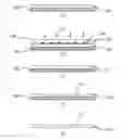
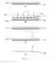
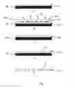
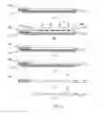
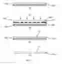
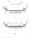
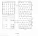
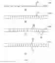
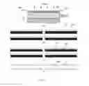
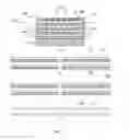
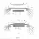
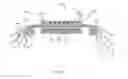
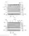
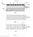
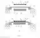
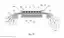
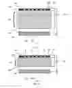
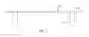
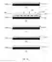
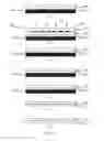
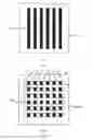
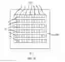
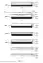
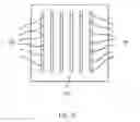
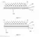
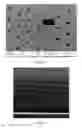
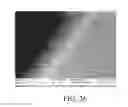
Sources:
- United States Patent and Trademark Office - verify current appl. status at the USPTO↗
Similar patent applications:
Recent applications in this class:
- » 20250083109 2025-03-13
Polymeric Composites Having Oriented Nanopores and Methods of Making the Same - » 20240139686 2024-05-02
RESIN MEMBRANE FILTER AND MANUFACTURING METHOD OF RESIN MEMBRANE FILTER - » 20240123409 2024-04-18
POROUS POLYMERIC MEMBRANE WITH TEAR PREVENTION RING - » 20230415100 2023-12-28
BIOCOMPATIBLE HIGH ASPECT-RATIO POROUS MEMBRANE - » 20230372878 2023-11-23
FILTER APPARATUS FOR SEMICONDUCTOR DEVICE FABRICATION PROCESS - » 20220379265 2022-12-01
Filter apparatus for semiconductor device fabrication process - » 20220314173 2022-10-06
Pillar template for making micropore membranes and methods of fabrication thereof - » 20220176325 2022-06-09
Porous polymeric membrane with tear prevention ring - » 20220143560 2022-05-12
ISOPOROUS POLYMER MEMBRANES - » 20210308628 2021-10-07
Biocompatible high aspect-ratio porous membrane