Two-Terminal Modulator
US20120194288A1
2012-08-02
13/353,810
2012-01-19
Abstract:
The invention is an electronic Two-Terminal Modulator. It is used electrically in series between a Power Source and a Target Device, and can modulate the power that is sent to the Target Device, at speeds and with modulating complexity that exceed present capability. The invention includes implementation of the modulator as a unit that is inserted into or appended to another device and is used to modulate the power in the other device.
Interested in similar patents?
Get notified when new applications in this technology area are published.
Classification:
H02J7/0063 » CPC main
Circuit arrangements for charging or depolarising batteries or for supplying loads from batteries with circuits adapted for supplying loads from the battery
H02J7/007182 » CPC further
Circuit arrangements for charging or depolarising batteries or for supplying loads from batteries; Regulation of charging or discharging current or voltage the cycle being controlled or terminated in response to electric parameters in response to battery voltage
H04B10/504 » CPC further
Transmission systems employing electromagnetic waves other than radio-waves, e.g. infrared, visible or ultraviolet light, or employing corpuscular radiation, e.g. quantum communication; Transmitters; Structural aspects; Laser transmitters using direct modulation
H01S5/0427 » CPC further
Semiconductor lasers; Processes or apparatus for excitation, e.g. pumping, e.g. by electron beams; Electrical excitation ; Circuits therefor for applying modulation to the laser
H03K7/00 IPC
Modulating pulses with a continuously-variable modulating signal
Description
BACKGROUND OF THE INVENTION
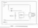
The example used is that of a laser diode powered by a battery. In the left side of FIG. 1, the laser diode is powered by the battery, but the power is not modulated, so the laser diode emits a steady light beam. Where it is desired that the laser diode emit a pulsing or otherwise modulated light beam, it is necessary to modulate the power that is sent to the laser diode.
One way to modulate the power is to insert a three-terminal modulating device into the circuit as shown in the example on the right side of FIG. 1. The three-terminal modulator is so-named because it connects to the other components of the circuit in three places (“terminals”), labelled A, B and C.
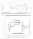
There are situations where it is inconvenient or impossible to insert a three-terminal modulator into a circuit. A Two-Terminal Modulator is shown in FIG. 2. It is so-named because it connects to the other components of the circuit in only two places, labelled D & E.
Two-Terminal Modulators have been implemented in a variety of ways, often using heaters and bi-metallic strips to flash ornamental light bulbs, but they are limited in speed and in the complexity of the modulation.
BRIEF SUMMARY OF THE INVENTION
The invention is an electronic Two-Terminal Modulator. It is used electrically in series between a Power Source and a Target Device, and can modulate the power that is sent to the Target Device, at speeds and with modulating complexity that exceed present capability.
The invention includes implementation of the Two-Terminal Modulator as a unit that is inserted into a battery compartment of an existing device and used to modulate the power in the other device.
BRIEF DESCRIPTION OF THE SEVERAL VIEWS OF THE DRAWING
FIG. 1. Comparison of Not-Modulated and Modulated Laser Diode
FIG. 2. Two-Terminal Modulator in Use
FIG. 3. Two-Terminal Modulator Block Diagram
FIG. 4. Use of Two-Terminal Modulator inside Battery Compartment
DETAILED DESCRIPTION OF THE INVENTION
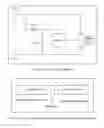
The invention is detailed in FIG. 3. Initially, the Capacitor starts to charge until it has enough voltage to operate the Oscillator. The Current Modulator or On/Off Switch is controlled by the Oscillator, and eventually starts passing current through itself and therefore from Terminal 1 to Terminal 2.
At times, during normal operation, the Current Modulator or On/Off Switch is passing all or most of the current passing through the Target Device, so insufficient current is available to power the Oscillator. At these times the Diode isolates the Capacitor from the input power and the Capacitor supplies the current that keeps the Oscillator running.
The invention can be implemented as a sufficiently-small separate stand-alone unit that is inserted into a battery compartment in series with the battery to easily convert an existing unmodulated device into a modulated device, as shown in FIG. 4.
The Two-Terminal Modulator is constructed using standard electronic methodologies.
Claims
This is a non-provisional application of provisional patent U.S. 61/436,936 filed on Jan. 27, 2011 and I claim all rights:1. Embodiments and embellishments of the electronic structure shown in FIG. 3.
2. A device that embodies the electronic structure shown in FIG. 3 as a unit that is to be inserted into or appended to a second electronic unit for the purpose of modulating the power used within the second electronic unit.
Images & Drawings included:
Sources:
- United States Patent and Trademark Office - verify current appl. status at the USPTO↗
Similar patent applications:
- » 20250040258
TWO-TERMINAL TANDEM SOLAR MODULE
Recent applications in this class:
- » 20250175023 2025-05-29
Accumulator with two interface devices - » 20250167573 2025-05-22
BATTERY SYSTEM FOR OPERATING POINT CONTROL OF POWER SYSTEMS - » 20250167572 2025-05-22
POWER SUPPLY DEVICE AND TERMINAL - » 20250149907 2025-05-08
BATTERY MANAGEMENT APPARATUS - » 20250141252 2025-05-01
ENERGY STORAGE CONVERTER, AND ENERGY STORAGE SYSTEM - » 20250141251 2025-05-01
MICROINVERTER-INTEGRATED BATTERY PARALLELING DEVICES - » 20250141250 2025-05-01
ELECTRICAL POWER SUPPLY WITH A DC/DC VOLTAGE CONVERTER - » 20250141249 2025-05-01
ELECTRICAL CIRCUIT FOR CONTROLLING POWER SUPPLY DEVICE IN AN ELECTRICAL DEVICE, AND ELECTRICAL DEVICE - » 20250132585 2025-04-24
POWER MODULE AND ELECTRICAL DEVICE - » 20250132584 2025-04-24
POWER SUPPLY CIRCUIT AND METHOD, AND VEHICLE EMPLOYING CIRCUIT