Method for shifting a semi-automatic powershift transmission
US20120216640A1
2012-08-30
13/405,925
2012-02-27
✅ Patent granted
US 8,864,624 B2
2014-10-21
-
-
Troy Chambers | Jude Agendia
RatnerPrestia
2032-07-27
Abstract:
A method for shifting a semi-automatic powershift transmission used in a motor vehicle during a manually triggered traction upshift involves the shift phases of the charging of an actuator of a clutch to be engaged, an overlap of the charging of the actuator of the clutch to be engaged and the emptying of an actuator of a clutch to be disengaged, and also involves an engine rotational speed alignment. The charging, the overlap and the engine rotational speed alignment are carried out simultaneously. In the shift process during a manually triggered shift, the driver perceives a change in engine rotational speed with only a minimal delay after the shift command.
Assignee:
- Dr. Ing. h.c. F. Porsche Aktiengesellschaft 1,102 🇩🇪 Stuttgart, Germany
Applicant:
Interested in similar patents?
Get notified when new applications in this technology area are published.
Classification:
F16H61/061 » CPC main
Control functions within change-speed- or reversing-gearings for conveying rotary motion; Smoothing ratio shift by controlling rate of change of fluid pressure using electric control means
F16D2500/1086 » CPC further
External control of clutches by electric or electronic means; System to be controlled; Gear Concentric shafts
Y10T74/19251 » CPC further
Machine element or mechanism; Gearing; Interchangeably locked Control mechanism
F16H61/682 IPC
Control functions within change-speed- or reversing-gearings for conveying rotary motion specially adapted for stepped gearings with interruption of drive
F16H2059/683 » CPC further
Control inputs to control units of change-speed-, or reversing-gearings for conveying rotary motion; Inputs being a function of gearing status Sensing pressure in control systems or in fluid controlled devices, e.g. by pressure sensors
F16H63/46 » CPC further
Control outputs to change-speed- or reversing-gearings for conveying rotary motion comprising signals other than signals for actuating the final output mechanisms Signals to a clutch outside the gearbox
F16D2500/5014 » CPC further
External control of clutches by electric or electronic means; Problem to be solved by the control system; Relating the actuator Filling the actuator cylinder with fluid
B60W30/19 » CPC further
Purposes of road vehicle drive control systems not related to the control of a particular sub-unit, e.g. of systems using conjoint control of vehicle sub-units, or advanced driver assistance systems for ensuring comfort, stability and safety or drive control systems for propelling or retarding the vehicle; Propelling the vehicle Improvement of gear change, e.g. by synchronisation or smoothing gear shift
F16D2500/70414 » CPC further
External control of clutches by electric or electronic means; Details about the implementation of the control system; Output parameters from the control unit; Target parameters to be controlled; Actuator parameters; Position Quick displacement to clutch touch point
F16D2500/3024 » CPC further
External control of clutches by electric or electronic means; Signal inputs from the actuator Pressure
F16H63/502 » CPC further
Control outputs to change-speed- or reversing-gearings for conveying rotary motion comprising signals other than signals for actuating the final output mechanisms; Signals to an engine or motor for smoothing gear shifts
B60W10/02 » CPC further
Conjoint control of vehicle sub-units of different type or different function including control of driveline clutches
F16D48/066 » CPC further
External control of clutches; Control by electric or electronic means, e.g. of fluid pressure Control of fluid pressure, e.g. using an accumulator
F16H59/00 IPC
Control of gearings conveying rotary motion
F16H59/00 IPC
Control inputs to control units of change-speed-, or reversing-gearings for conveying rotary motion
F16D48/06 IPC
External control of clutches Control by electric or electronic means, e.g. of fluid pressure
F16H61/06 IPC
Control functions within change-speed- or reversing-gearings for conveying rotary motion; Smoothing ratio shift by controlling rate of change of fluid pressure
F16H63/50 IPC
Control outputs to change-speed- or reversing-gearings for conveying rotary motion comprising signals other than signals for actuating the final output mechanisms Signals to an engine or motor
F16H59/68 IPC
Control inputs to control units of change-speed-, or reversing-gearings for conveying rotary motion Inputs being a function of gearing status
B60W10/11 » CPC further
Conjoint control of vehicle sub-units of different type or different function including control of change-speed gearings Stepped gearings
B60W10/06 » CPC further
Conjoint control of vehicle sub-units of different type or different function including control of propulsion units including control of combustion engines
F16H61/688 » CPC further
Control functions within change-speed- or reversing-gearings for conveying rotary motion specially adapted for stepped gearings without interruption of drive with two inputs, e.g. selection of one of two torque-flow paths by clutches
Description
CROSS-REFERENCE TO RELATED APPLICATION
This U.S. patent application claims priority to German Patent Application DE 102011000957.4, filed Feb. 28, 2011, which is incorporated by reference herein in its entirety.
FIELD OF THE INVENTION
The invention relates to a method for shifting a semi-automatic powershift transmission used in a motor vehicle during a manually triggered traction upshift, involving the shift phases of the charging of an actuator of a clutch to be engaged, an overlap of the charging of the actuator of the clutch to be engaged and the emptying of an actuator of a clutch to be disengaged, and also involving an engine rotational speed alignment.
BACKGROUND OF THE INVENTION
In a powershift transmission, which is for example a dual clutch transmission, the different shift phases of charging, overlap and engine rotational speed alignment are carried out sequentially one after the other in conventional traction upshifts. A high level of shift comfort is obtained in this way. Automatically triggered shifts can take place quickly and in a jerk-free manner. In the case of manually triggered (tipped) shifts, the charging and overlap phases are perceived as a considerable delay between the shift command and the time at which the change in rotational speed takes place. The driver experiences this as being non-spontaneous and sluggish.
EP 1 953 424 A2, which is incorporated by reference herein, describes a method for controlling the shift pressure in an actuator of an electrohydraulically controlled motor vehicle transmission. Here, a setpoint value for the start pressure at the end of the charging phase is defined as a function of the torque output by the drive engine.
From DE 10 2005 016 672 A1, which is incorporated by reference herein, it is known to refine the adaptation steps during the charging of shift elements of an automatic gearbox.
DE 30 10 865 A1, which is incorporated by reference herein, describes a method for controlling an automatic multi-stage transmission in motor vehicles. Here, the charging state of the clutch is monitored in order to save time at the transition of the charging and overlap phases.
SUMMARY OF THE INVENTION
Disclosed herein is a method of the type mentioned in the introduction such that, during a to manually triggered shift, the driver perceives a change in engine rotational speed with only a minimal delay after the shift command.
The charging, the overlap and the engine rotational speed alignment are carried out simultaneously.
As a result of the simultaneous execution of charging, overlap and rotational speed alignment, the change in rotational speed begins with only a minimal delay after the manual shift command.
The driver barely perceives this minimal delay, and therefore feels an immediate reaction to his manually triggered shift command. This minimal delay is usually considerably less than 200 ms. However, the shift according to the invention can lead to jerks. As a result of the simultaneous intervention of the drive machine/of the engine for rotational speed alignment, the jerk can be kept to a minimum, and is additionally perceived as a spontaneous reaction in the case of manually triggered shifts. In the case of manually triggered shifts, in particular in a sports car, said jerk is not perceived negatively.
It is provided in particular that the charging is terminated on the basis of a pressure sensor signal. This makes it possible for the charging to be carried out and ended in an optimal fashion.
The powershift transmission is in particular a dual clutch transmission.
BRIEF DESCRIPTION OF THE DRAWING
Preferred refinements of the invention will emerge from the following description. A preferred exemplary embodiment of the invention will be explained in more detail on the basis of the drawing, without the invention being restricted thereto. The drawing also shows an exemplary embodiment according to the prior art.
DETAILED DESCRIPTION OF THE DRAWING
In the drawing:
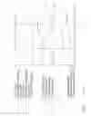
FIG. 1 shows diagrams A, B and C for illustrating the method known from the prior art,
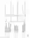
FIG. 2 shows diagrams A, B and C for illustrating the method according to the invention.
In FIGS. 1 and 2, the respective diagrams A, B and C show, on the same time axis t, the dependency of characteristic variables. The diagram A shows a torque-time characteristic curve, the diagram B shows a pressure-time characteristic curve, and the diagram C shows a rotational speed-time characteristic curve.
The individual torques, pressures and rotational speeds are specified in greater detail in the legends for the respective FIGS. 1 and 2.
FIG. 1 shows the conventional shift process, that is to say the sequential process of charging, overlap and rotational speed alignment. It can be seen from diagrams A and B that, during the charging, the actual pressure and the setpoint pressure in the actuator of the clutch K2, that is to say of the clutch to be engaged, is initially increased, resulting in an increase in the clutch torque of the clutch K2. During said time interval, the actual pressure and the setpoint pressure in the actuator of the clutch K1, that is to say of the clutch to be disengaged, and also the clutch torque of the clutch K1, remain unchanged. Only thereafter does the overlap interval take place, with further increasing pressure (setpoint pressure/actual pressure) in the actuator for the clutch K2 (further charging) and activation of the actuator for the clutch K1 to decrease the pressure (setpoint pressure/actual pressure) in said actuator, and therefore the emptying of said actuator. Said interval corresponds to that in diagram A, which illustrates the decrease in the clutch torque K1 and the increase in the clutch torque K2. It can be seen from diagram A that the engine rotational speed alignment, illustrated by the engine torque IST and in diagram C by the engine rotational speed, takes place only after the overlap is complete.
It can be seen from the diagrams of FIG. 1 that the charging and overlap phases are perceived as a significant delay between the shift command and the time at which the change in rotational speed takes place. The shift command takes place at the time of the discontinuous increase in the driver demand engine torque in diagram A or of the discontinuous increase in the setpoint pressure in the actuator of clutch K2 in diagram B.
FIG. 2 shows the characteristic curves of FIG. 1 as explained above, but for the method according to aspects of the invention, that is to say the simultaneous execution of charging, overlap and engine rotational speed alignment. It can be seen that the engine intervention takes place at the same time as the start of the manually triggered (tipped) shift, and an immediate overlap of the clutch torques K1 and K2 takes place, as can be seen from diagram A, and the immediate overlap of setpoint pressure and actual pressure of the actuators of the clutches K1 and K2 also takes place, as per diagram B. The actuator of the clutch K2 to be engaged is immediately acted on with approximately the maximum setpoint pressure, and the emptying of the actuator of the clutch K1 to be disengaged is also commenced at this time. With regard to the actual characteristic curves of the pressure shown in diagram B, the emptying of the clutch K1 to be disengaged and the charging of the clutch K2 to be engaged take place approximately in the same short period of time, which is significantly shorter than in the conventional shift process as per FIG. 1, and the engine rotational speed alignment also takes place in this time interval, as can be seen from diagrams C and from the engine torque IST from diagram A.
The termination of the charging of the actuator of the clutch K2 to be engaged takes place on the basis of a pressure sensor signal. The K2 setpoint pressure characteristic curve according to diagram B in FIG. 2 accordingly differs significantly from that according to diagram B in FIG. 1.
Owing to the simultaneous charging, overlap and engine rotational speed alignment in the method according to aspects of the invention, the change in rotational speed begins with only a minimal delay after the manual shift command.
The relatively long time interval in the conventional shift process is denoted in FIG. 1 by t1, and the shortened time interval according to aspects of the invention is denoted in FIG. 2 by t2.
Claims
1.-3. (canceled)
4. A method for shifting a semi-automatic powershift transmission used in a motor vehicle during a manually triggered traction upshift, said method comprising the steps of:
charging an actuator of a clutch to be engaged,
overlapping the charging step with a step of emptying an actuator of a clutch to be disengaged, and
aligning an engine rotational speed,
wherein the charging, overlapping and aligning steps are carried out simultaneously.
5. The method as claimed in claim 4, wherein the charging step is terminated on the basis of a pressure sensor signal.
6. The method as claimed in claim 4, wherein a powershift transmission configured as a dual clutch transmission is shifted.
Images & Drawings included:

Sources:
- United States Patent and Trademark Office - verify current appl. status at the USPTO↗
Recent applications in this class:
- » 20250277525 2025-09-04
GEAR SHIFTING CONTROL METHOD, VEHICLE CONTROLLER, VEHICLE AND STORAGE MEDIUM - » 20250271060 2025-08-28
CONTROL SYSTEMS TO DAMPEN OUTPUT SHAFT OSCILLATIONS, VEHICLES AND TRANSMISSIONS INCORPORATING THE SAME, AND METHODS THEREFOR - » 20230047435 2023-02-16
Method and control unit for resolving a tooth-on-tooth position of a positive-locking shifting element of an automated manual transmission - » 20210148460 2021-05-20
Shift control apparatus for vehicle automatic transmission - » 20210108719 2021-04-15
Control apparatus for vehicle - » 20200309260 2020-10-01
Shift control device for automatic transmission - » 20200217415 2020-07-09
A Method For Operating A Vehicle Transmission - » 20190257416 2019-08-22
Method and device for improving the gear-changing quality of a motor vehicle having an automatic transmission - » 20190219160 2019-07-18
Transmission control system - » 20190136970 2019-05-09
TRANSMISSION DEVICE
Recent applications for this Assignee:
- » 20250267774 2025-08-21
METHOD FOR ANALYZING SOUNDS IN A VEHICLE AND ACTIVATING A DISCO MODE IN THE VEHICLE BASED ON THE SOUNDS - » 20250262932 2025-08-21
METHOD FOR SIMULTANEOUSLY PERFORMING VEHICLE AND SMARTPHONE FUNCTIONS USING A HARD KEY ON VEHICLE - » 20250193489 2025-06-12
METHOD AND DEVICE FOR REFLECTING PUBLIC MOOD DURING A REAL-TIME TRANSMISSION - » 20250058597 2025-02-20
DAMPING ARRANGEMENT FOR AN AXLE OF A MOTOR VEHICLE AND MOTOR VEHICLE - » 20250058596 2025-02-20
DECOUPLING CARRIER FOR AN ELECTRO-HYDRAULIC UNIT - » 20250042485 2025-02-06
AIR-GUIDING ELEMENT AND MOTOR VEHICLE COMPRISING AN AIR-GUIDING ELEMENT - » 20250023976 2025-01-16
INTEGRATED VEHICLE SOFTWARE AND REMOTE APPLICATION THEREFORE - » 20250020186 2025-01-16
MULTI-CHAMBER AIR SPRING, METHOD FOR OPERATING THE MULTI-CHAMBER AIR SPRING - » 20250020185 2025-01-16
Vibration damper and motor vehicle with an active chassis - » 20250018758 2025-01-16
Motor vehicle having an active damping control