Tractor
US20120217082A1
2012-08-30
13/389,035
2010-07-22
✅ Patent granted
US 8,833,501 B2
2014-09-16
WO; PCT/EP2010/060611; 20100722
WO; WO2011/015458; 20110210
Hau Phan | Jacob Meyer
2031-04-16
Abstract:
A tractor has a chassis (10) which supports an engine (4) towards the front thereof. A deflecting shield (8) is positioned to the rear of the engine to deflect sideways hot air which has passed over the engine, and a tank (15) for the storage of urea based fluid for injection into an exhaust system of the engine is located behind the engine to the rear of the deflecting shield. The chassis to the rear of the engine may have an open-topped section (11a) between the engine (4) and a transmission housing (12), the tank being at least partially housed within the open-topped section of the chassis to shield the tank from the hot air which has passed over the engine and from the heating effects of the sun.
Inventors:
- Robert Heisler 5 🇩🇪 Marktoberdorf, Germany
- Gerhard Mariner 7 🇩🇪 Bidingen, Germany
- Guido Nägele 4 🇩🇪 Marktoberdorf, Germany
- Andreas Kleinhenz 2 🇩🇪 Rosshaupten, Germany
- Klaus-Jurgen Satzger 1 🇩🇪 Baisweil, Germany
- Hans Heinle 6 🇩🇪 Biessenhofen, Germany
Assignee:
- AGCO Corporation 621 🇺🇸 Duluth, GA, United States
- AGCO GMBH 56 🇩🇪 Marktoberdorf, Germany
Applicant:
Interested in similar patents?
Get notified when new applications in this technology area are published.
Classification:
F01N2610/1406 » CPC further
Adding substances to exhaust gases; Arrangements for the supply of substances, e.g. conduits Storage means for substances, e.g. tanks or reservoirs
F01N3/2066 » CPC main
Exhaust or silencing apparatus having means for purifying, rendering innocuous, or otherwise treating exhaust for rendering innocuous by thermal or catalytic conversion of noxious components of exhaust characterised by methods of operation; Control specially adapted for catalytic conversion ; Methods of operation or control of catalytic converters Selective catalytic reduction [SCR]
B60Y2200/221 » CPC further
Type of vehicle; Off-Road Vehicles; Agricultural vehicles Tractors
F01N2610/02 » CPC further
Adding substances to exhaust gases the substance being ammonia or urea
F01N2610/1413 » CPC further
Adding substances to exhaust gases; Arrangements for the supply of substances, e.g. conduits; Storage means for substances, e.g. tanks or reservoirs Inlet and filling arrangements therefore
F01N2340/04 » CPC further
Dimensional characteristics of the exhaust system, e.g. length, diameter or volume of the apparatus; Spatial arrangements of exhaust apparatuses characterised by the arrangement of an exhaust pipe, manifold or apparatus in relation to vehicle frame or particular vehicle parts
B60K11/08 » CPC further
Arrangement in connection with cooling of propulsion units Air inlets for cooling; Shutters or blinds therefor
Y02A50/20 » CPC further
in human health protection, e.g. against extreme weather Air quality improvement or preservation, e.g. vehicle emission control or emission reduction by using catalytic converters
Y02T10/12 » CPC further
Road transport of goods or passengers; Internal combustion engine [ICE] based vehicles Improving ICE efficiencies
Y02T10/12 » CPC further
Road transport of goods or passengers; Internal combustion engine [ICE] based vehicles Improving ICE efficiencies
F01N3/08 IPC
Exhaust or silencing apparatus having means for purifying, rendering innocuous, or otherwise treating exhaust for rendering innocuous
B62D49/00 IPC
Tractors
B60K13/04 IPC
Arrangement in connection with combustion air intake or gas exhaust of propulsion units concerning exhaust
F01N3/20 IPC
Exhaust or silencing apparatus having means for purifying, rendering innocuous, or otherwise treating exhaust for rendering innocuous by thermal or catalytic conversion of noxious components of exhaust characterised by methods of operation; Control specially adapted for catalytic conversion ; Methods of operation or control of catalytic converters
Description
This invention relates to tractors and in particular to storage arrangements on such tractors for fluids such as urea based fluids which are injected under pressure into the exhaust gases of the engines of such tractors to reduce toxic emissions.
There is a requirement to provide a compact and convenient storage arrangement which also assists in protecting the urea based fluid from excessive heat as such fluids should be maintained, if possible, below 60° C. otherwise they start to break down into their corrosive constituents which can damage components of the urea injection system. Particular problems can arise when the fluid is stored in close proximity to the tractor's engine which is a source of considerable heat.
Thus in accordance with the present invention there is provided a tractor having a chassis which supports an engine towards the front thereof, a deflecting shield positioned to the rear of the engine to deflect sideways hot air which has passed over the engine, and a tank for the storage of urea based fluid for injection into an exhaust system of the engine, the tank being located behind the engine to the rear of the deflecting shield and wherein the chassis to the rear of the engine has an open-topped section between the engine and a transmission housing and the tank is at least partially housed within the open-topped section of the chassis.
The chassis to the rear of the engine may have an open-topped section between the engine and a transmission housing, the tank being at least partially housed within the open-topped section of the chassis.
The above arrangement is well shielded from the hot air which has passed over the engine and being at least partially within the chassis is also protected from the heating effects of the sun.
The tank is preferably of a moulded plastic construction and has an upper section which includes a filler neck which is located outside the chassis for easy access.
The tank may also be moulded around other components which extend within the open-topped section of the chassis.
The upper section of the tank may include an outlet for the stored fluid and may support a level sensing arrangement for the fluid.
The present invention will now be described, by way of example only, with reference to the accompanying drawings in which:
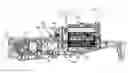
FIG. 1 shows diagrammatically a plan view of a typical prior art tractor tank arrangement;
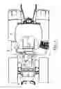
FIG. 2 shows a section on the line B-B of FIG. 2 or 5 of a tractor chassis in accordance with the present invention;
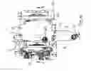
FIG. 3 shows a plan view of the tractor chassis of FIG. 2;
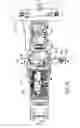
FIG. 4 shows part of FIG. 2 on a larger scale;
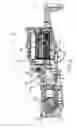
FIG. 5 shows, on a larger scale, a section on the line A-A of FIG. 3;
FIG. 6 shows part of FIG. 3 on a larger scale, and
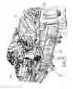
FIG. 7 shows a perspective view of part of the chassis if FIGS. 2 and 3.
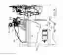
FIG. 1 shows a typical tractor 1 which has an engine bay 2 in which is diagrammatically shown a cooling package 3 for an engine 4. The cooling package 3 includes a core heater/radiator assembly 3a with a cooling fan 3b. Ambient air is sucked by fan 3b through the heater/radiator assembly 3a and thereby heated up. The air is then passed over engine 4 and especially hot components like turbocharger 5 or the exhaust ducting 6. Due to hot surface temperatures (turbocharger 5 at a level of about 700° C. exhaust ducting 6 at about 300° C.) the air passing the engine (shown by arrows X) is enormously heated up, so air temperatures of up to 250° C. occur. To avoid any heat impact on the cab 7, a heat shield part shown diagrammatically at 8 is provided to guide the air out of the engine bay 2 before impacting on the front 7a of the cab 7. Thus the air is routed nearly sideways, as shown by arrows W. This results in additional heat impact on fluids such as diesel fuel or urea based fluids for exhaust treatment which are traditionally stored in tanks systems 9a and 9b on both sides of the tractor.
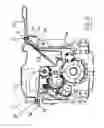
A tractor in accordance with the present invention has a chassis 10 (see FIG. 2) constructed from a number of cast components. Essentially the chassis comprises a front portion 11, a central transmission housing 12 and a rear back axle housing 13 (shown diagrammatically) which are bolted together to form the complete chassis.
The tractor engine 4 is mounted on the front portion 11 of the chassis which is basically U-shaped in cross section leaving, to the rear of the engine, an opened topped section 11a of the chassis in which, in accordance with the present invention, a storage tank 15 for storing a urea based fluid for injecting into the engine exhaust gases is located. The engine is covered by an engine bonnet 2a and the heat shield 8 protects the front portion 7a of the cab from the hot air which has passed over the engine and other hot components such as the turbocharger 5 and the exhaust ducting 6.
As can been seen from FIG. 2, the engine 4 is connected with the tractor transmission within housing 12 by a drive shaft 16 which extends through the open topped section 11a of the chassis. FIGS. 2, 4 and 5 show that the storage tank 15 is shaped around the drive shaft 16. The tank is secured to flanges 11b of the chassis by screws 17 which extend through strengthening inserts 18 in the tank to engage holes 19 in the flanges 11b or a bracket 11c carried by flanges 11b.
As can be seen most clearly in FIGS. 3 and 4, the tank has a filler neck 20 closed by a cap 21. Filler neck 20 is provided a portion 22 of the tank 15 which extends outside the chassis 11, for example in the vicinity of the steps in to the cab of the tractor, in order to provide easy access for the filling of the tank. The upper portion of the tank also includes a unit 23 which includes an outlet for the stored fluid and a level sensor to provide an indication as to the amount of fluid remaining in the storage tank 15.
As will be appreciated, by housing the storage tank within the opened topped section 11a of the chassis to the rear of the engine the tank is well shielded from hot air which has passed over the engine by shield 8 and, being at least partially within the chassis, is also protected from the heating effects of the sun. Thus the urea based fluid stored in the tank 15 is able to be maintained below the 60° C. preferred level either without requiring cooling or with a significantly reduced cooling requirement.
As will be appreciated, the precise shape of the storage tank 15 depends on the other components which may pass through or be housed within the open top section 11a of the chassis. Since the tank is preferably formed from plastics material using a moulding process its shape can be carefully tailored to provide the maximum storage volume within the free space in the section 11a of the chassis. The tank may be partially within the chassis as described above or may be entirely within the chassis if the layout of the tractor permits this.
Claims
1. A tractor having a chassis which supports an engine towards the front thereof, a deflecting shield positioned to the rear of the engine to deflect sideways hot air which has passed over the engine, and a tank for the storage of urea based fluid for injection into an exhaust system of the engine, the tank being located behind the engine to the rear of the deflecting shield and wherein the chassis to the rear of the engine has an open-topped section between the engine and a transmission housing and the tank is at least partially housed within the open-topped section of the chassis.
2. A tractor according to claim 1 in which the tank is of a moulded plastic construction and has an upper section which includes a filler neck which is located outside the chassis for easy access.
3. A tractor according to claim 1 in which the tank is moulded around other components which extend within the open-topped section of the chassis.
4. A tractor according to claim 1 in which the upper section of the tank includes an outlet for the stored fluid and supports a level sensing arrangement for the fluid.
5. The tractor according to claim 1 in which the tank is of a moulded plastic construction and has an upper section which includes a filler neck which is located outside the chassis for easy access, wherein which the tank is moulded around other components which extend within the open-topped section of the chassis.
6. The tractor according to claim 1 in which the tank is of a moulded plastic construction and has an upper section which includes a filler neck which is located outside the chassis for easy access, wherein the upper section of the tank includes an outlet for the stored fluid and supports a level sensing arrangement for the fluid.
7. The tractor according to claim 2 in which the tank is moulded around other components which extend within the open-topped section of the chassis, wherein the upper section of the tank includes an outlet for the stored fluid and supports a level sensing arrangement for the fluid.
Images & Drawings included:
Sources:
- United States Patent and Trademark Office - verify current appl. status at the USPTO↗
Similar patent applications:
- » 20210341043
Tractor, travel power transmission apparatus for a tractor, and tractor provided with the travel power transmission apparatus for a tractor - » 20080246252
Heating device usable with a tractor trailer, a tractor trailer including the same, and a method of heating a tractor trailer - » 20180111648
Deflector arrangement for a tractor, a tractor, and a method for adjusting a deflector arrangement for a tractor - » 20230257036
TRACTOR, COMMERCIAL VEHICLE, RANGE OF TRACTORS AND METHOD FOR CONFIGURING A TRACTOR - » 20220135148
Truck or tractor vehicle with adjustable panhard bar and method for adjusting alignment of a truck or tractor vehicle cab relative to a truck or tractor vehicle frame - » 20090260909
Assembling Method of Tractor and Tractor - » 20100060029
Tractor cabin comprising at least one fairing with an air deflector and air deflector for a tractor cabin - » 20060145450
Control device for a tractor provided with a system for detecting pivoting and articulating angles between said tractor and a trailer - » 20070083341
Tractor-trailer having self-contained apparatus on-board tractor for estimating trailer weight - » 20050217156
Warning plate assembly for indicating the excess width of a tractor, in particular and agricultural tractor
Recent applications in this class:
- » 20250290439 2025-09-18
DESULFURIZATION METHOD - » 20250264047 2025-08-21
POST-PROCESSING SYSTEM - » 20250250919 2025-08-07
ROBUST CONTROL SYSTEMS AND METHODS OF CATALYST TEMPERATURE STABILITY WITH HEATER ASSISTANCE - » 20250188860 2025-06-12
DIESEL EXHAUST FLUID TANK CONDUIT CONNECTED TO AIR COMPRESSOR AND METHOD - » 20250154888 2025-05-15
DECOMPOSITION CHAMBER WITH GUIDE SWIRL MIXER - » 20250146433 2025-05-08
CATALYTIC PARTIAL WALL-FLOW FILTER - » 20250101898 2025-03-27
ULTRA-COMPACT POST-PROCESSING SYSTEM, SUPERCHARGER ASSEMBLY AND ENGINE - » 20250101897 2025-03-27
SELECTIVE CATALYTIC REDUCTION (SCR) SYSTEM AND ENGINE - » 20250092809 2025-03-20
Heater control in heavy-duty motor vehicle engines - » 20250052182 2025-02-13
EXHAUST STRUCTURE AND INJECTOR ATTACHMENT MEMBER
Recent applications for this Assignee:
- » 20240326073 2024-10-03
Aerial boom with through-fan spray - » 20240308290 2024-09-19
Height-adjustable agricultural vehicles and methods of transferring loads therein - » 20240306626 2024-09-19
Tri-directional break-away boom assembly - » 20230405499 2023-12-21
Sprayer filtering system - » 20230371435 2023-11-23
Agricultural baler - » 20230358707 2023-11-09
METHODS OF MEASURING HARVESTED CROP MATERIAL - » 20230341322 2023-10-26
TEMPERATURE COMPENSATION SYSTEM AND METHOD FOR NIR SAMPLE ON BALER - » 20230337563 2023-10-26
Mounting assembly for a steerable wheel with variable track width - » 20230271654 2023-08-31
System and method for adjusting the chassis height of a machine - » 20230210058 2023-07-06
Knot tightener for baler twine