Assembly of wet electrostatic precipitator
US20120222282A1
2012-09-06
13/394,828
2010-09-09
✅ Patent granted
US 9,009,944 B2
2015-04-21
WO; PCT/CA2010/001404; 20100909
WO; WO2011/029186; 20110317
David Bryant | Steven A Maynard
2031-01-16
Abstract:
Wet electrostatic precipitator (WESP) collector tube bundles are formed by a procedure in which strips of conductive material are corrugated, intended abutting surfaces of the corrugated strips are abraded, adhesive is applied to the abraded surfaces, multiple ones of the corrugated strips are assembled with corrugation in abutting relationship, and outer panels are assembled with the resulting hexagonal tube bundle.
Assignee:
- Megtec Turbosonic Inc. 1 🇨🇦 Waterloo, Canada
Applicant:
Interested in similar patents?
Get notified when new applications in this technology area are published.
Classification:
B32B3/30 » CPC further
Layered products comprising a layer with external or internal discontinuities or unevennesses, or a layer of non-planar form ; Layered products having particular features of form characterised by a particular shape of the outline of the cross-section of a continuous layer; characterised by a layer with cavities or internal voids ; characterised by an apertured layer characterised by a layer formed with recesses or projections, e.g. hollows, grooves, protuberances, ribs
B32B5/02 » CPC further
Layered products characterised by the non- homogeneity or physical structure, i.e. comprising a fibrous, filamentary, particulate or foam layer; Layered products characterised by having a layer differing constitutionally or physically in different parts characterised by structural features of a layer
B32B5/024 » CPC further
Layered products characterised by the non- homogeneity or physical structure, i.e. comprising a fibrous, filamentary, particulate or foam layer; Layered products characterised by having a layer differing constitutionally or physically in different parts characterised by structural features of a layer Woven fabric
B32B2250/20 » CPC further
Layers arrangement All layers being fibrous or filamentary
B32B2260/021 » CPC further
Layered product comprising an impregnated, embedded, or bonded layer wherein the layer comprises an impregnation, embedding, or binder material; Composition of the impregnated, bonded or embedded layer Fibrous or filamentary layer
B32B2260/046 » CPC further
Layered product comprising an impregnated, embedded, or bonded layer wherein the layer comprises an impregnation, embedding, or binder material; Impregnation, embedding, or binder material Synthetic resin
B32B2262/101 » CPC further
Composition or structural features of fibres which form a fibrous or filamentary layer or are present as additives; Inorganic fibres Glass fibres
B32B2262/106 » CPC further
Composition or structural features of fibres which form a fibrous or filamentary layer or are present as additives; Inorganic fibres Carbon fibres, e.g. graphite fibres
B32B2307/202 » CPC further
Properties of the layers or laminate having particular electrical or magnetic properties, e.g. piezoelectric Conductive
B32B2307/714 » CPC further
Properties of the layers or laminate; Other properties Inert, i.e. inert to chemical degradation, corrosion
B32B2457/00 » CPC further
Electrical equipment
Y10T29/49801 » CPC further
Metal working; Method of mechanical manufacture Shaping fiber or fibered material
Y10T29/49826 » CPC further
Metal working; Method of mechanical manufacture Assembling or joining
Y10T29/49906 » CPC further
Metal working; Method of mechanical manufacture; Assembling or joining Metal deforming with nonmetallic bonding
B32B38/10 IPC
Ancillary operations in connection with laminating processes Removing layers, or parts of layers, mechanically or chemically
B32B1/08 IPC
Layered products having a general shape other than plane Tubular products
B23P11/00 IPC
Connecting or disconnecting metal parts or objects by metal-working techniques not otherwise provided for
B31D3/005 » CPC further
Making articles of cellular structure, e.g. insulating board Making cellular structures from corrugated webs or sheets
B32B5/26 » CPC further
Layered products characterised by the non- homogeneity or physical structure, i.e. comprising a fibrous, filamentary, particulate or foam layer; Layered products characterised by having a layer differing constitutionally or physically in different parts characterised by the presence of two or more layers which are next to each other and are fibrous, filamentary, formed of particles or foamed one layer being a fibrous or filamentary layer another layer also being fibrous or filamentary
B31D3/00 IPC
Making articles of cellular structure, e.g. insulating board
B32B7/12 » CPC further
Layered products characterised by the relation between layers; Layered products characterised by the relative orientation of features between layers, or by the relative values of a measurable parameter between layers, i.e. products comprising layers having different physical, chemical or physicochemical properties; Layered products characterised by the interconnection of layers; Interconnection of layers using interposed adhesives or interposed materials with bonding properties
B32B9/00 » CPC further
Layered products characterised by particular substances used
B32B9/00 » CPC further
Layered products comprising a layer of a particular substance not covered by groups -
B03C3/16 » CPC further
Separating dispersed particles from gases or vapour, e.g. air, by electrostatic effect; Plant or installations having external electricity supply wet type
B32B3/28 » CPC main
Layered products comprising a layer with external or internal discontinuities or unevennesses, or a layer of non-planar form ; Layered products having particular features of form characterised by a particular shape of the outline of the cross-section of a continuous layer; characterised by a layer with cavities or internal voids ; characterised by an apertured layer characterised by a layer comprising a deformed thin sheet, i.e. the layer having its entire thickness deformed out of the plane , e.g. corrugated, crumpled
B32B3/12 » CPC further
Layered products comprising a layer with external or internal discontinuities or unevennesses, or a layer of non-planar form ; Layered products having particular features of form characterised by a discontinuous layer, i.e. formed of separate pieces of material characterised by a layer of regularly- arranged cells, e.g. a honeycomb structure
B32B5/28 » CPC further
Layered products characterised by the non- homogeneity or physical structure, i.e. comprising a fibrous, filamentary, particulate or foam layer; Layered products characterised by having a layer differing constitutionally or physically in different parts characterised by the presence of two or more layers which are next to each other and are fibrous, filamentary, formed of particles or foamed one layer being a fibrous or filamentary layer impregnated with or embedded in a plastic substance
B32B27/04 » CPC further
Layered products comprising synthetic resin as impregnant, bonding, or embedding substance
B03C3/49 » CPC further
Separating dispersed particles from gases or vapour, e.g. air, by electrostatic effect; Constructional details or accessories or operation thereof; Electrode constructions; Collecting-electrodes tubular
B03C3/64 » CPC further
Separating dispersed particles from gases or vapour, e.g. air, by electrostatic effect; Constructional details or accessories or operation thereof; Electrode constructions; Use of special materials other than liquids synthetic resins
Description
FIELD OF THE INVENTION
This invention relates to the assembly of a wet electrostatic precipitator (WESP), in particular collector tube bundles therefor.
BACKGROUND TO THE INVENTION
Wet electrostatic precipitators (WESP) have been used for many years to remove dust, acid mist and other particulates from water-saturated air and other gases by electrostatic means. In a WESP, particulates and/or mist laden water-saturated air flows in a region of the precipitator between discharge and collecting electrodes, where the particulates and/or mist is electrically charged by corona emitted from the high voltage discharge electrodes. As the water-saturated gas flows further within the WESP, the charged particulates matter and/or mist is electrostatically attracted to grounded collecting plates or electrodes where it is collected. The accumulated materials are continuously washed off by both an irrigating film of water and periodic flushing.
This type of system is used to remove pollutants from gas streams exhausting from various industrial sources, such as incinerators, coke ovens, glass furnaces, non-ferrous metallurgical plants, coal-fired generation plants, forest product facilities, food drying plants and petrochemical plants.
The electrodes used in WESPs are commonly formed of stainless steel. In International Patent Application Publication No. WO 2008/154,735 and International Patent Application No. PCT/CA2010/000377 assigned to the assignee hereof and the disclosures of which are incorporated herein by reference, we have described the provision of WESP parts constructed of electrically-conductive corrosion and spark-resistant carbon composites. Such materials show comparable or superior properties to stainless steel and permit WESPs to be constructed at lower cost.
SUMMARY OF INVENTION
We provide herein a procedure for assembly of WESP electrode bundles from conductive carbon composites. The present invention uses a so-called “stacked panel” method of forming hexagonal tubes.
In such a procedure, conductive carbon composite material is molded into corrugated form, the corrugations of mating surfaces of adjacent panels are abraded to expose carbon fibres, adjacent corrugated strips are adhered at their abutting corrugations to form a hexagonal tube bundle, and the corrugated tube bundle is assembled with outer structural panels.
The procedure described herein allows for carbon-carbon contact required for conduction. The procedure is flexible, providing the ability to manufacture one stock generic panels for different size tube bundles with low capital and operating costs. The composite material is light weight yet able to withstand sparking and corrosion.
BRIEF DESCRIPTION OF DRAWING
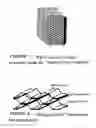
FIG. 1 is a perspective view of a WESP electric bundle product according to one embodiment of the invention;
FIG. 2 is a perspective view of stacked panels according to one embodiment of the invention;
FIG. 3 is a schematic perspective view of the panel molding step;
FIG. 4 is a schematic perspective view of abrasion of the bonding areas of the panel;
FIG. 5 is a schematic perspective view of the application of bonding material to the abraded areas of the panel;
FIG. 6 is a perspective view of an outer panel with hexagonal corrugation;
FIG. 7 is a perspective view of the outer panel with V corrugation;
FIG. 8 is a perspective view of an inner panel constructed of conductive carbon composite material with hexagonal corrugation; and
FIGS. 9 to 15 illustrate the sequence of assembly of the electrode stack.
DESCRIPTION OF PREFERRED EMBODIMENT
Referring to the drawings, the first step in the assembly procedure is the formation of elongate strips of conductive carbon material which are molded into a corrugated shape (FIGS. 2 and 3).
Any desired molding procedure may be used which enables corrugated strips of carbon composite material to be formed, including vacuum assisted resin transfer molding, as schematically illustrated in FIG. 3 and/or resin infusion.
The conductive composite material utilized herein is a conductive hybrid composite material designed for highly corrosive operating conditions including dry and saturated mist environments with elevated temperatures. The hybrid composite material is a blend of glass and/or carbon fibres and thermosetting resins developed for applications subjected to corona voltage flash over, spark, erosion, corrosion and power arc, including wet electrostatic precipitation. Such resins include thermosetting polyvinyl ester resin.
In particular, the composite material comprises carbon fiber woven roving and/or carbon fibres within a thermosetting resin where extremely strong molecular building blocks form totally cross-linked structures bonded to each other and at interconnects. Carbon fibres are used as the reinforcing material in areas of the strips required to be conductive while a glass fibre wrap can be used to improve the structural strength of the panel assembly (tube bundle).
The surface of the formed strips then are abraded at the raised portions of the corrugations to expose the conductive carbon fibres for fibre-fibre contact with adjacent mated panels. This abrasion provides for stronger bonding and proper electrical conductivity in the bonded areas. Bonding resin then is applied to the abraded mating surface of the corrugated strips (FIGS. 4 and 5).
Another panel then is stacked with the first panel with the corrugations abutting one another to become adhered together (FIG. 2). This procedure is repeated until a stack of hexagonal tubes of the desired size has been prepared.
The outer panels are the main structural components of the tube bundles and holds the dead and earthquake loads of both the upper equipment and the lower tube bundles.
The outer panels are broken down into two corrugation forms. One corrugation form is a “Hat” section corrugation having a hexagonal-shaped ‘H’ corrugation (FIG. 6) and the other is a hex-shaped V corrugation (FIG. 7). These panels, including flanges and stiffening ribs can be constructed of glass-fibre reinforced materials.
The panels may be assembled into the final tube bundles (FIG. 1) utilizing a stack clamp/jig table. The assembly steps are shown in FIGS. 9 to 15.
SUMMARY OF THE DISCLOSURE
In summary of this disclosure, the present invention provides a method of assembly of conductive tube bundles using conductive carbon composite materials. Modifications are possible within the scope of this invention.
Claims
What we claim is:1. A method of forming a hexagonal tube bundle, which comprises:
forming strips of conductive material into corrugated strips,
abrading intended abutting portion of the corrugated strips,
applying adhesive the abraded mating surface(s), and
assembling multiple ones of the corrugated strips with corrugations in abutting relationship until the desired bundle size has been achieved.
2. The method of claim 1, wherein said conductive material is a conductive carbon composite material.
3. The method of claim 3, wherein the conductive carbon composite material is a hybrid composite material comprising a blend of carbon fibreglass and/or carbon fibres and thermosetting resin.
4. The method of claim 1 further comprising assembling outer panels with the hexagonal tube bundles.
Images & Drawings included:


Sources:
- United States Patent and Trademark Office - verify current appl. status at the USPTO↗
Recent applications in this class:
- » 20250187296 2025-06-12
WATER-STOP FILM - » 20250187295 2025-06-12
WINDOW AND MANUFACTURING METHOD THEREOF - » 20250091314 2025-03-20
Honeycomb Core Material - » 20250001721 2025-01-02
THERMOPLASTIC BAGS WITH ENHANCED DART IMPACT RESISTANCE - » 20240375373 2024-11-14
PREFORM PATCH AND METHOD OF SUBSEQUENT REINFORCEMENT OF A FIBRE COMPOSITE COMPONENT - » 20240326374 2024-10-03
METHOD FOR MANUFACTURING LAMINATE SHAPED TO HAVE IRREGULARITIES, LAMINATE FOR SHAPING IRREGULARITIES, AND LAMINATE SHAPED TO HAVE IRREGULARITIES - » 20240326373 2024-10-03
Hollow fusion panel made of a combination of new and recycled materials and producing method thereof - » 20240092054 2024-03-21
THERMOPLASTIC BAGS WITH COMPLEX STRETCH PATTERNS - » 20240042727 2024-02-08
THERMOPLASTIC BAGS WITH COMPLEX STRETCH PATTERNS - » 20240017520 2024-01-18
SHEET HAVING CLOSED CELL LAYER