Bumper for a vehicle
US20120223536A1
2012-09-06
13/261,082
2009-06-30
✅ Patent granted
US 9,610,910 B2
2017-04-04
WO; PCT/SE2009/000333; 20090630
WO; WO2011/002344; 20110106
Jason S Morrow | E Turner Hicks
Mark P. Stone
2029-09-21
Abstract:
A bumper with integrated crumple is formed from a central beam (11) and two outer beams (12,13), the ends of the central beam and adjacent ends of the outer beams being curved and welded together to form the crash boxes (14,15).
Assignee:
- GESTAMP HARDTECH AB 56 🇸🇪 Lulea, Sweden
Applicant:
Interested in similar patents?
Get notified when new applications in this technology area are published.
Classification:
B60R19/26 IPC
Wheel guards; Radiator guards, e.g. grilles ; Obstruction removers; Fittings damping bouncing force in collisions; Bumpers, i.e. impact receiving or absorbing members for protecting vehicles or fending off blows from other vehicles or objects; Arrangements for mounting bumpers on vehicles comprising yieldable mounting means
B60R19/34 » CPC further
Wheel guards; Radiator guards, e.g. grilles ; Obstruction removers; Fittings damping bouncing force in collisions; Bumpers, i.e. impact receiving or absorbing members for protecting vehicles or fending off blows from other vehicles or objects; Arrangements for mounting bumpers on vehicles comprising yieldable mounting means destroyed upon impact, e.g. one-shot type
B60R19/18 » CPC main
Wheel guards; Radiator guards, e.g. grilles ; Obstruction removers; Fittings damping bouncing force in collisions; Bumpers, i.e. impact receiving or absorbing members for protecting vehicles or fending off blows from other vehicles or objects Means within the bumper to absorb impact characterised by the cross-section;
B60R2019/1813 » CPC further
Wheel guards; Radiator guards, e.g. grilles ; Obstruction removers; Fittings damping bouncing force in collisions; Bumpers, i.e. impact receiving or absorbing members for protecting vehicles or fending off blows from other vehicles or objects; Means within the bumper to absorb impact characterised by the cross-section;; Structural beams therefor, e.g. shock-absorbing made of metal
Description
TECHNICAL FIELD OF THE INVENTION
The invention deals with a bumper for a vehicle, comprising a bumper beam and two crash boxes with closed profile. The bumper beams are oriented transverse to the vehicle, while the crash boxes are oriented along the vehicle and are fastened to the vehicle.
PURPOSE AND BRIEF DESCRIPTION OF THE INVENTION
One purpose of the invention is to simplify and economise on the manufacture of a bumper of this kind. This is achieved in that the bumper beam comprises a central beam and two outer beams, the ends of the central beam and the adjacent ends of the outer beams being curved and welded together to form the crash boxes.
BRIEF DESCRIPTION OF THE DRAWINGS SHOWING A SAMPLE EMBODIMENT OF THE INVENTION
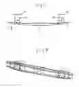
FIG. 1 is a top view of a bumper.
FIG. 2 is a perspective view of the same bumper.
FIG. 3 shows a magnified view of part of the bumper in FIGS. 1 and 2.
FIG. 4 is an exploded view of FIG. 3.
DETAILED DESCRIPTION OF THE ILLUSTRATED AND PREFERRED EXAMPLE OF THE INVENTION
The bumper shown in the figures consists of a central beam 11 and two outer beams 12,13 and the three beams are welded together and form integrated crash boxes 14,15 which have fastening plates 16,17 for attachment to supporting parts of the vehicle, often for attachment to corresponding fastening plates on the side rails of the vehicle. All three beams have a U-profile with the opening toward the vehicle. The ends of the beams facing each other are curved toward the vehicle and form in pairs crash boxes which are thus integrated parts of the beams.
FIGS. 3 and 4 show a magnified view of the crash box 15 and adjacent parts of the beams 11 and 13. The larger part of the central flange 18 of the central beam consists of a broad middle groove 19. As best seen in FIG. 4, the exploded view, the middle groove deepens toward the curved ends so that the central beam has an inverted U profile 20 there. The outer beam 13 has a corresponding appearance with a middle groove 21 and this beam also has an inverted U profile 22 at the curved ends. The two U-profiles 20 and 22 and their extensions in the form of the end edges 23, 24 of the original U-profiles are placed against each other and welded together. One edge of the inverted U-profile is preferably placed overlapping the other to provide a stronger joint, as shown in FIG. 3.
The two inverted U-profiles 20,22 thus form crash boxes 15 having a closed cross section and oriented in the lengthways direction of the vehicle, i.e., transverse to the bumper beam 11,12,13 and integrated with it. The fastening plate 17 is welded to the ends of the two inverted U-profiles 20,22.
Crash box 14 is formed in the same way.
Claims
1. Bumper for a vehicle, comprising a bumper beam and two crash boxes with closed profile, characterised in that the bumper beam comprises a central beam (11) and two outer beams (12, 13), the ends of the central beam and adjacent ends of the outer beams being curved and welded together to form the crash boxes (14, 15).
2. Bumper according to claim 1, characterised in that the ends of the crash boxes are welded to a fastening plate (16).
3. Bumper according to claim 1, characterised in that the three beams (11, 12, 13) have a U-profile with its opening toward the vehicle and these profiles are inverted where they form the crash boxes (14, 15).
4. Bumper according to claim 2, characterised in that the three beams (11, 12, 13) have a U-profile with its opening toward the vehicle and these profiles are inverted where they form the crash boxes (14, 15).
Images & Drawings included:


Sources:
- United States Patent and Trademark Office - verify current appl. status at the USPTO↗
Similar patent applications:
- » 20220118928
VEHICLE BUMPER, COMPOSITE MATERIALS FOR VEHICLE BUMPERS, AND METHODS THEREOF - » 20160355150
Vehicle bumper beam and method for manufacturing vehicle bumper beam - » 20100038923
Vehicle bumper assembly and associated vehicle comprising this bumper assembly - » 20070284895
Vehicle bumper assembly and associated vehicle comprising this bumper assembly - » 20200130967
Dock bumpers and/or vehicles bumpers - » 20150291114
Vehicle Bumper Beam, Associated Bumper Beam Assembly and Vehicle - » 20200398775
Accessory assembly for a bumper region of a vehicle and a vehicle bumper accessory assembly - » 10794813
Apparatus to attach a proximity sensor to an energy absorbing vehicle bumper - » 10297153
Motor vehicle bumper - » 10809273
Motor-vehicle bumper assembly
Recent applications in this class:
- » 20250256670 2025-08-14
FRONT STRUCTURE OF VEHICLE - » 20250236251 2025-07-24
CROSSMEMBER - » 20250236250 2025-07-24
VEHICLE BUMPER BEAM - » 20250229736 2025-07-17
BUMPER BEAM - » 20250196792 2025-06-19
BUMPER HAVING REINFORCEMENT PLATE AND IMPROVED CRASH PROPERTY - » 20250178552 2025-06-05
BUMPER FOR A MOTOR VEHICLE - » 20250170976 2025-05-29
VEHICLE FRONT PORTION STRUCTURE - » 20250145098 2025-05-08
BUMPER REINFORCEMENT MEMBER AND METHOD FOR MANUFACTURING SAME - » 20250074346 2025-03-06
VEHICLE BUMPER - » 20250065835 2025-02-27
OPEN CROSS SECTION BUMPER REINFORCEMENT
Recent applications for this Assignee:
- » 20220001932 2022-01-06
Overlapping elongate steel structure and method of producing such an elongate steel structure - » 20210292860 2021-09-23
Method and system for cooling hot components - » 20210086711 2021-03-25
Crash box for a bumper - » 20200231218 2020-07-23
Vehicle side structure - » 20200180293 2020-06-11
PROCESS OF APPLYING A CFRP PATCH ON A STEEL PLATE TO BE FORMED - » 20200122663 2020-04-23
Bumper beam with reinforcement patch - » 20190344737 2019-11-14
Lightweight bumper beam - » 20190061658 2019-02-28
Bumper beam - » 20180370470 2018-12-27
Bumper - » 20180281710 2018-10-04
Bumper beam