Radar sensor device having at least one planar antenna device
US20120223852A1
2012-09-06
13/496,397
2010-07-16
✅ Patent granted
US 9,310,478 B2
2016-04-12
WO; PCT/EP2010/060316; 20100716
WO; WO2011/032745; 20110324
John B. Sotomayor | Marcus Windrich
Kenyon & Kenyon LLP
2032-05-18
Abstract:
A radar sensor device having at least one planar antenna device that includes a plurality of vertically oriented antenna columns which are configured as a sparse array in one plane in parallel at defined mutual distances and which each have at least two line-fed patch elements, the sparse array of antenna columns is designed to have such a minimal redundancy that the amount of defined distances among the antenna columns in the sparse array is at least equal to all of the different distances between any two antenna columns of a corresponding non-sparse array of a planar antenna device having the same antenna aperture and the same characteristics of the antenna columns, but is the most minimum possible number.
Assignee:
- Robert Bosch GMBH 19,123 🇩🇪 Stuttgart, Germany
Applicant:
Interested in similar patents?
Get notified when new applications in this technology area are published.
Classification:
G01S2013/93185 » CPC further
Systems using the reflection or reradiation of radio waves, e.g. radar systems; Analogous systems using reflection or reradiation of waves whose nature or wavelength is irrelevant or unspecified; Radar or analogous systems specially adapted for specific applications for anti-collision purposes of land vehicles Controlling the brakes
G01S2013/93271 » CPC further
Systems using the reflection or reradiation of radio waves, e.g. radar systems; Analogous systems using reflection or reradiation of waves whose nature or wavelength is irrelevant or unspecified; Radar or analogous systems specially adapted for specific applications for anti-collision purposes of land vehicles; Sensor installation details in the front of the vehicles
G01S13/00 IPC
Systems using the reflection or reradiation of radio waves, e.g. radar systems; Analogous systems using reflection or reradiation of waves whose nature or wavelength is irrelevant or unspecified
G01S13/931 » CPC main
Systems using the reflection or reradiation of radio waves, e.g. radar systems; Analogous systems using reflection or reradiation of waves whose nature or wavelength is irrelevant or unspecified; Radar or analogous systems specially adapted for specific applications for anti-collision purposes of land vehicles
H01Q1/3233 » CPC further
Details of, or arrangements associated with, antennas; Adaptation for use in or on movable bodies; Adaptation for use in or on road or rail vehicles characterised by the application wherein the antenna is used particular used as part of a sensor or in a security system, e.g. for automotive radar, navigation systems
H01Q21/065 » CPC further
Antenna arrays or systems; Arrays of individually energised antenna units similarly polarised and spaced apart; Two dimensional planar arrays Patch antenna array
G01S2013/9321 » CPC further
Systems using the reflection or reradiation of radio waves, e.g. radar systems; Analogous systems using reflection or reradiation of waves whose nature or wavelength is irrelevant or unspecified; Radar or analogous systems specially adapted for specific applications for anti-collision purposes of land vehicles Velocity regulation, e.g. cruise control
G01S13/93 IPC
Systems using the reflection or reradiation of radio waves, e.g. radar systems; Analogous systems using reflection or reradiation of waves whose nature or wavelength is irrelevant or unspecified; Radar or analogous systems specially adapted for specific applications for anti-collision purposes
H01Q21/22 » CPC further
Antenna arrays or systems; Arrays of individually energised antenna units similarly polarised and spaced apart Antenna units of the array energised non-uniformly in amplitude or phase, e.g. tapered array or binomial array
H01Q1/32 IPC
Details of, or arrangements associated with, antennas; Adaptation for use in or on movable bodies Adaptation for use in or on road or rail vehicles
H01Q21/06 IPC
Antenna arrays or systems Arrays of individually energised antenna units similarly polarised and spaced apart
Description
FIELD OF THE INVENTION
The present invention relates to a radar sensor device having at least one planar antenna device that includes a plurality of vertically oriented antenna columns which are configured as a sparse array in one plane in parallel at defined mutual distances and which each have at least two line-fed patch elements. The present invention also relates to a device, in particular a driver assistance system of a motor vehicle.
BACKGROUND INFORMATION
Within the framework of driver assistance systems, radar sensors are increasingly being used in motor vehicles for sensing the traffic environment, for example, for radar-based distance control (adaptive cruise control systems/ACC). Such a cruise control system is described, for example, in “Adaptive Fahrgeschwindigkeitsregelung ACC,” (Adaptive Cruise Control ACC) yellow technical instruction series, 2002 edition by Robert Bosch GmbH.
Due to the flat design and ease of manufacture thereof, for example in etching processes, what are generally referred to as planar antenna devices or patch antennas are particularly suited for use in the above described radar sensors. In the case of such antennas, it is a question of a two-dimensional array of radiating resonators (antenna elements, respectively patch elements/patches), each having a defined amplitude and phase. By superimposing the radiation diagrams of the individual patch elements, one obtains the resulting radiation diagram of the antenna, the rows being responsible for the azimuthal characteristic and the columns for the elevation characteristic. The antenna elements are usually configured in vertically oriented antenna columns.
Many radar sensors used for driving-environment sensing in automotive applications make use of such planar antenna designs. One advantage of the planar antenna designs is the low overall depth of the radar sensors resulting therefrom. Greater flexibility is thereby attained for the installation location of the radar sensors, and new fields of application emerge, such as installation in the side region of the vehicle. Besides the size of the radar sensors, the costs of manufacturing the same are naturally also a determining factor. Especially in planar antenna designs, where a signal evaluation is performed on the individual channels (no HF beam-forming), the number of mixers used constitutes a considerable cost factor. In this context, the configuration, respectively the number of antenna patches plays an important role. Conventional radar sensors having planar antenna devices generally have a uniform linear array (ULA) structure. The antenna columns having the patch elements are spaced at equidistant intervals which generally reside within the range of half of the wavelength in air (λ/2).
The antenna aperture is the decisive factor in achieving a best possible angular precision using the radar sensor system. The larger the antenna aperture is, the better is the angular precision. If the antenna aperture is provided with a uniform linear array structure, as in previously known radar sensors, a large number of mixers is then required, thereby increasing the total costs for the sensors.
German Patent Application No. DE 100 36 131 A1 describes a radar sensor used for sensing the traffic situation in the driving environment of a motor vehicle. It includes a carrier element having an array of patch antennas in the form of a combination of a filled subarray of patch antennas and a sparse subarray of patch antennas. However, the patch antennas are provided redundantly, i.e., the signal relations are measured multiple times.
SUMMARY
In accordance with the present invention, an example radar sensor device having at least one planar antenna device is provided that includes a plurality of vertically oriented antenna columns which are configured as a sparse array in one plane in parallel at defined mutual distances and which each feature at least two line-fed patch elements, the sparse array of antenna columns being configured with such a minimal redundancy that the total amount of defined distances among the antenna columns in the sparse array is at least equal to all of the different distances between any two antenna columns of a corresponding non-sparse array of a planar antenna device having the same antenna aperture and the same antenna column characteristics, but is the most minimum possible number.
By implementing these measures, a very good compromise is obtained between the requirement for single-valuedness and precision of the angles through the use of what are generally referred to as minimum redundancy arrays (MRA) of antenna columns. The antenna columns having patch elements are not configured equidistantly, but using sparse arrays in consideration of the minimal redundancy principle. This advantageously leads to a substantial further reduction in the number of antenna columns, respectively patch elements and, thus, also in the number of required mixers, thereby achieving a cost reduction in the manufacturing of the radar sensor. Due to the fact that each distance between the antenna columns, thus each phase relationship is present at least once, but as infrequently as possible, a minimal redundancy is achieved. In a conventional, respectively non-sparse array of a planar antenna device having the same aperture, all of the different distances among any given combinations of antenna columns must be present in order to ensure single-valuedness (uniqueness).
The defined mutual distances of the antenna columns may each be an integral multiple of a constant basic distance. It is advantageous that the constant basic distance be smaller than or equal to one half of the wavelength in air. A single-valuedness is then obtained for the +/−90 degree range.
BRIEF DESCRIPTION OF THE DRAWINGS
An exemplary embodiment of the present invention is described below with reference to the figures.
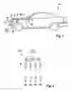
FIG. 1 shows a schematic representation of the main components of a driver assistance system, respectively of an adaptive cruise control device in a motor vehicle.
FIG. 2 shows a schematic representation of an array of a conventional planar antenna device having four antenna columns.
FIG. 3 shows a schematic representation of an array of a planar antenna device having three antenna columns for a first specific embodiment of the radar sensor device according to the present invention.
FIG. 4 shows a schematic representation of an array of a planar antenna device having four antenna columns for a second specific embodiment of the radar sensor device according to the present invention.
Detailed Description of Example Embodiments
A motor vehicle 10 illustrated in FIG. 1 having an adaptive cruise control device 11 as a driver assistance system features a radar sensor device 12 as an object detection sensor which is mounted on the front end of motor vehicle 10 and in whose housing a control device 14 of adaptive cruise control device 11 is also accommodated. Radar sensor device 12 is used for detecting objects in the surrounding field of motor vehicle 10. Radar sensor device 12 is connected to control device 14. Control device 14 is connected via a data bus 16 (CAN, MOST or the like) to an electronic drive control unit 18, a brake system control unit 20, as well as to an HMI control unit 22 of a human-machine interface. In further exemplary embodiments (not shown), control unit 14 and HMI control unit 22 may also be integrated in a control device of adaptive cruise control device 12, in particular in a shared housing.
With the aid of a multi-beam radar, radar sensor device 12 measures the distances, relative velocities and azimuthal angles of objects located ahead of vehicle 10 that reflect radar waves. The raw data received at regular intervals, for example every 10 ms, are evaluated in control device 14 in order to identify and track individual objects and, in particular, to recognize a vehicle that is immediately ahead on the same lane, and to select it as a target object.
As is also readily apparent from FIG. 1, radar sensor device 12 according to the present invention features a planar antenna device having arrays 15.2 or 15.3 of antenna columns 15b through 15h (see FIGS. 3 and 4).
FIG. 2 illustrates a planar antenna device, respectively a conventional non-sparse array 15.1 having four vertically oriented antenna columns 15a which are configured in one plane in parallel at mutual distances. Antenna columns 15a are configured at equidistant, i.e., constant mutual basic distances which correspond to half wavelength λ in air. As is apparent in FIG. 2, 0.5·wavelength λ in air, 1.0·wavelength λ in air and 1.5·wavelength λ in air are manifested as different distances.
FIG. 3 shows a planar antenna device for a first specific embodiment of radar sensor device 12 according to the present invention having three vertically oriented antenna columns 15b, 15c and 15d which are configured as a sparse array 15.2 in one plane in parallel at defined mutual distances and which each feature a plurality of line-fed patch elements 23. Sparse array 15.2 of antenna columns 15b, 15c and 15d is designed to have such a minimal redundancy that the total amount of defined distances among antenna columns 15b, 15c and 15d in sparse array 15.2 is at least equal to all different distances between any two antenna columns 15a of corresponding non-sparse array 15.1 from FIG. 1 of a planar antenna device having the same antenna aperture and the same characteristics of antenna columns 15a, but is the lowest, most minimum possible number. As is also apparent from FIG. 3, a distance of 0.5·wavelength λ in air is provided between antenna columns 15b and 15c, and a distance amounting to 1.0·wavelength λ in air is provided between antenna columns 15c and 15d. Moreover, a distance of 1.5·wavelength λ in air remains between antenna columns 15b and 15d.
FIG. 4 shows a planar antenna device for a second specific embodiment of radar sensor device 12 according to the present invention having four vertically oriented antenna columns 15e, 15f, 15g and 15h which are configured as a sparse array 15.3 in one plane in parallel at defined mutual distances. As is apparent from FIG. 4, a distance of 0.5·wavelength λ in air is provided between antenna columns 15e and 15f; a distance of 1.5·wavelength λ in air is provided between antenna columns 15f and 15g; and a distance amounting to 1.0·wavelength λ in air is provided between antenna columns 15g and 15h. In addition, a distance of 2.0·wavelength λ in air remains between antenna columns 15e and 15g; a distance of 2.5·wavelength λ in air remains between antenna columns 15f and 15h; and a distance of 3.0·wavelength λ in air remains between antenna columns 15e and 15h.
The defined mutual distances of antenna columns 15a through 15g are each an integral multiple of a constant basic distance, namely half of wavelength λ in air.
Claims
1-4. (canceled)
5. A radar sensor device, comprising:
at least one planar antenna device that includes a plurality of vertically oriented antenna columns which are configured as a sparse array in one plane in parallel at defined mutual distances and which each have at least two line-fed patch elements, wherein the sparse array of antenna columns has a minimal redundancy so that a total amount of defined distances among the antenna columns in the sparse array is at least equal to all of the distances between any two of the antenna columns of a corresponding non-sparse array of a planar antenna device having a same antenna aperture and same characteristics of the antenna columns, but is the lowest possible number.
6. The radar sensor device as recited in claim 5, wherein the defined mutual distances of the antenna columns are each an integral multiple of a constant basic distance.
7. The radar sensor device as recited in claim 6, wherein the constant basic distance is smaller than or equal to one half of a wavelength in air.
8. A driver assistance system of a motor vehicle, comprising:
at least one radar sensor device for detecting objects in a surrounding field of the motor vehicle, the radar sensor device including at least one planar antenna device that includes a plurality of vertically oriented antenna columns which are configured as a sparse array in one plane in parallel at defined mutual distances and which each have at least two line-fed patch elements, wherein the sparse array of antenna columns has a minimal redundancy so that a total amount of defined distances among the antenna columns in the sparse array is at least equal to all of the distances between any two of the antenna columns of a corresponding non-sparse array of a planar antenna device having a same antenna aperture and same characteristics of the antenna columns, but is the lowest possible number; and
a control device connected to the at least one radar sensor device.
Images & Drawings included:


Sources:
- United States Patent and Trademark Office - verify current appl. status at the USPTO↗
Recent applications in this class:
- » 20250291054 2025-09-18
Methods and Structures for Reducing Leakage from Air Waveguide Antennas - » 20250264606 2025-08-21
RADAR-BASED ANALYTICS - » 20250264605 2025-08-21
COMPOSITION FOR RADAR TRANSMISSION COVER AND RADAR TRANSMISSION COVER MANUFACTURED USING SAME - » 20250244474 2025-07-31
VEHICULAR RADAR SENSING SYSTEM WITH THREE-DIMENSIONAL ANTENNA CONFIGURATION - » 20250244473 2025-07-31
SECURE FLASHLESS BOOTING FOR AUTOMOTIVE RADAR - » 20250237759 2025-07-24
Method For Sensing Surroundings Of A Vehicle By Means Of A Sensor System On The Basis Of Consecutive Interconnection Of Subarrays Of The Sensor System, And Sensor System And Vehicle - » 20250231295 2025-07-17
Method and Apparatus - » 20250224511 2025-07-10
RADAR APPARATUS AND RADAR APPARATUS SUPPORT STRUCTURE - » 20250199165 2025-06-19
APPARATUS AND METHOD FOR RECOGNIZING NEARBY OBJECT IN PERSONAL MOBILITY DEVICE - » 20250189664 2025-06-12
MEASUREMENT GRID EFFICIENCY FOR DYNAMIC OCCUPANCY GRID COMPUTATION
Recent applications for this Assignee:
- » 20250154889 2025-05-15
PRESSURE CONTROL IN AN EXHAUST AFTERTREATMENT SYSTEM - » 20250154580 2025-05-15
ENZYME TRANSLOCATORS IN NANOGAP WITH 3' -ESTERS - » 20250147582 2025-05-08
METHOD FOR DETERMINING AN EYE DISTANCE IN A PAIR OF DATA GLASSES, AND DATA GLASSES - » 20250146568 2025-05-08
DRIVE ASSEMBLY AND VEHICLE HAVING SUCH A DRIVE ASSEMBLY - » 20250146495 2025-05-08
Flexible Pump Assembly for Use in a Fan Drive - » 20250140882 2025-05-01
FUEL CELL SYSTEM HAVING ENERGY RECUPERATION - » 20250137810 2025-05-01
METHOD FOR MATCHING A DIGITAL ROAD MAP - » 20250137033 2025-05-01
DNA UNFOLDING USING A FREE-END TAG FLOW MODIFIER - » 20250119751 2025-04-10
A BLUETOOTH COMMUNICATION METHOD AND SYSTEM - » 20250118116 2025-04-10
Diagnostic Protocol Search With Improved Efficiency