METHOD FOR PRODUCING PLASTIC TANKS FOR LIQUIDS
US20120261063A1
2012-10-18
13/462,484
2012-05-02
Abstract:
A method for producing plastic tanks for liquids with a tapping valve, wherein the tank is produced from a tubular parison by blow molding, and wherein a holding flange or a threaded socket is formed on the tank. After the drain outlet of the tank has been cut out of the tank wall inside the holding flange or the threaded socket, the finished preassembled tapping valve is welded by its inlet socket to the holding flange or the threaded socket of the tank by a welding machine, during which the tank is centered and held in the welding machine by the holding flange or the threaded socket.
Assignee:
- Protechna S.A. 38 🇨🇭 Fribourg, Switzerland
Interested in similar patents?
Get notified when new applications in this technology area are published.
Classification:
B29C65/02 » CPC main
Joining of preformed parts ; Apparatus therefor by heating, with or without pressure
B29C65/7802 » CPC further
Joining of preformed parts ; Apparatus therefor; Means for handling the parts to be joined, e.g. for making containers or hollow articles, e.g. means for handling sheets, plates, web-like materials, tubular articles, hollow articles or elements to be joined therewith; Means for discharging the joined articles from the joining apparatus Positioning the parts to be joined, e.g. aligning, indexing or centring
B29C66/1222 » CPC further
General aspects of processes or apparatus for joining preformed parts; General aspects dealing with the joint area or with the area to be joined; Particular design of joint configurations particular design of the joint cross-sections; Joint cross-sections combining only two joint-segments; Tongue and groove joints; Tenon and mortise joints; Stepped joint cross-sections; Joint cross-sections combining only two joint-segments, i.e. one of the parts to be joined comprising only two joint-segments in the joint cross-section comprising at least a lapped joint-segment
B29C66/1224 » CPC further
General aspects of processes or apparatus for joining preformed parts; General aspects dealing with the joint area or with the area to be joined; Particular design of joint configurations particular design of the joint cross-sections; Joint cross-sections combining only two joint-segments; Tongue and groove joints; Tenon and mortise joints; Stepped joint cross-sections; Joint cross-sections combining only two joint-segments, i.e. one of the parts to be joined comprising only two joint-segments in the joint cross-section comprising at least a butt joint-segment
B29C66/131 » CPC further
General aspects of processes or apparatus for joining preformed parts; General aspects dealing with the joint area or with the area to be joined; Particular design of joint configurations particular design of the joint cross-sections; Single flanged joints; Fin-type joints; Single hem joints; Edge joints; Interpenetrating fingered joints; Other specific particular designs of joint cross-sections not provided for in groups - Single flanged joints, i.e. one of the parts to be joined being rigid and flanged in the joint area
B29C66/1312 » CPC further
General aspects of processes or apparatus for joining preformed parts; General aspects dealing with the joint area or with the area to be joined; Particular design of joint configurations particular design of the joint cross-sections; Single flanged joints; Fin-type joints; Single hem joints; Edge joints; Interpenetrating fingered joints; Other specific particular designs of joint cross-sections not provided for in groups - ; Single flanged joints, i.e. one of the parts to be joined being rigid and flanged in the joint area Single flange to flange joints, the parts to be joined being rigid
B29C66/612 » CPC further
General aspects of processes or apparatus for joining preformed parts; General aspects of joining tubular articles; General aspects of joining long products, i.e. bars or profiled elements; General aspects of joining single elements to tubular articles, hollow articles or bars; General aspects of joining several hollow-preforms to form hollow or tubular articles; Joining from or joining on the inside Making circumferential joints
B65D77/0466 » CPC further
Packages formed by enclosing articles or materials in preformed containers, e.g. boxes, cartons, sacks or bags; Articles or materials enclosed in two or more containers disposed one within another the inner and outer containers being rigid or semi-rigid and the outer container being of polygonal cross-section not formed by folding or erecting one or more blanks the inner container having a polygonal cross-section the containers being mounted on a pallet
B29C49/04 » CPC further
Blow-moulding, i.e. blowing a preform or parison to a desired shape within a mould; Apparatus therefor; Combined blow-moulding and manufacture of the preform or the parison Extrusion blow-moulding
B29C65/20 » CPC further
Joining of preformed parts ; Apparatus therefor by heating, with or without pressure using heated tools with direct contact, e.g. using "mirror"
B29C2793/0018 » CPC further
Shaping techniques involving a cutting or machining operation; Cutting out for making a hole
B29C2793/009 » CPC further
Shaping techniques involving a cutting or machining operation after shaping
Y10T156/1062 » CPC further
Adhesive bonding and miscellaneous chemical manufacture; Methods of surface bonding and/or assembly therefor with cutting, punching, tearing or severing Prior to assembly
B32B37/06 IPC
Methods or apparatus for laminating, e.g. by curing or by ultrasonic bonding characterised by the heating method
Description
This application is a continuation of U.S. application Ser. No. 11/203,662 filed Aug. 12, 2005 which claims priority to German Patent Application No. 10 2004 039 963.8 filed Aug. 18, 2004, all of which are incorporated herein by reference.
BACKGROUND OF THE INVENTION
1. Field of the Invention
The present invention relates to a method for producing plastic tanks for liquids, especially for use as inner tanks for liquid shipping and storage tanks with an outer jacket in the form of a cage or sheet material and a pallet-like support frame, which are constructed as rectangular-solid or cubic tanks with four sidewalls, an upper base with a filling socket that can be closed with a cap, a lower base, and a drain outlet in the lower section of a sidewall for connection to a tapping valve.
2. Description of the Related Art
DE 102 42 954 A1 describes a method of this type for producing plastic tanks for liquids, in which the inlet connection of the tapping valve is welded to the blow-molded tank. This method has been found to be impracticable.
SUMMARY OF THE INVENTION
The object of the invention is to develop a method with a high production capacity for producing plastic tanks for liquids that are equipped with a tapping valve.
In accordance with the invention, this object is met achieved by a production method in which the tanks are produced from a tubular parison by blow molding, wherein a holding flange or a threaded socket is formed on the rear section of a lower recess of the front wall of the tank, which recess receives the tapping valve. The recess of the tanks is cut out inside the holding flange or the threaded socket with a cutting tool to produce the drain outlet of the tanks. The finished preassembled tapping valve is welded to the holding flange or threaded socket in a welding machine.
The various features of novelty which characterize the invention are pointed out with particularity in the claims annexed to and forming a part of the disclosure. For a better understanding of the invention, its operating advantages, specific objects attained by its use, reference should be had to the drawing and descriptive matter in which there are illustrated and described preferred embodiments of the invention.
BRIEF DESCRIPTION OF THE DRAWING
In the drawing:
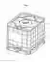
FIG. 1 is a perspective view of a shipping and storage tank for liquids constructed as a pallet tank; and
FIGS. 2 and 3 are enlarged views of the outlet region of the tank, half in a side view and half in a vertical section.
DESCRIPTION OF THE INVENTION
The shipping and storage tank 1 for liquids (FIG. 1), which can be used as a disposable and reusable tank, has as its principal components (1) a replaceable rectangular-solid plastic tank 2 for liquids with four sidewalls 3-6, which tank 2 has a filling socket 7 in the upper base 9 that can be closed with a cap 8 and a tapping valve 10, especially a flap valve, which is connected to a drain outlet 11 in a dome-shaped recess 12 in the front wall 3 of the tank 2 in the region of the lower base 13 of the tank for receiving the tapping valve 10, and (2) an outer cage 14 that consists of intersecting horizontal and vertical metal bars 15, 16 and a pallet-like support frame 17 with standard European dimensions of length and width, whose sheet-metal base 18, which is constructed as a shallow base pan, supports the plastic tank 2.
The tank 2 is produced from a tubular parison by blow molding, wherein a holding flange 19 (FIG. 2) or a threaded socket 20 (FIG. 3) is formed on the rear section 21 of a lower recess 12 of the front wall 3 of the tank 2, which recess 12 receives the tapping valve 10. After the tank 2 has cooled, its recess 12 is cut out inside the holding flange 19 or the threaded socket 20 with a cutting tool to produce the drain outlet 11 of the tank 2. The finished preassembled tapping valve 10, whose injection-molded plastic body 22 has an inlet socket 23 and an outlet socket 24, is then welded by its inlet socket 23 to the holding flange 19 or the threaded socket 20 of the tank 2 by a welding machine, especially a heat-reflection butt-welding machine, during which the tank 2 is centered and held in the welding machine by the holding flange 19 or the threaded socket 20.
While specific embodiments of the invention have been shown and described in detail to illustrate the inventive principles, it will be understood that the invention may be embodied otherwise without departing from such principles.
Claims
I claim:1. A method for producing plastic tanks for liquids, especially for use as inner tanks for liquid shipping and storage tanks with an outer jacket in the form of a cage or sheet material and a pallet-like support frame, which are constructed as rectangular-solid or cubic tanks with four sidewalls, an upper base with a filling socket that can be closed with a cap, a lower base, and a drain outlet in the lower section of a sidewall for connection to a tapping valve, the method comprising producing the tanks from a tubular parison by blow molding, wherein during the same blow molding a holding flange or a threaded socket is formed on a rear section of a lower recess of the front wall of the tank, which recess receives the tapping valve; cutting out the recess of the tanks inside the holding flange or the threaded socket with a cutting tool to produce the drain outlet of the tanks; and welding the finished preassembled tapping valve to the holding flange or threaded socket in a welding machine, wherein, for welding the tapping valve to the tanks, centering the tanks and holding the tanks in the welding machine opposite the tapping valve by the holding flange or threaded socket which are formed on the tank, wherein the welding step includes welding the inlet socket of the tapping valve to the holding flange or the threaded socket of the tanks by heat-reflection butt welding.
Images & Drawings included:


Sources:
- United States Patent and Trademark Office - verify current appl. status at the USPTO↗
Similar patent applications:
Recent applications in this class:
- » 20250033293 2025-01-30
RESIN JOINED BODY MANUFACTURING METHOD - » 20240316872 2024-09-26
Method for Embedding an RFID Tag Into a Mat - » 20240075690 2024-03-07
High-frequency welding for headgear - » 20220410495 2022-12-29
PREPREG, PREPARATION METHOD THEREOF AND FIBER REINFORCED COMPOSITE MATERIAL PREPARED THEREFROM - » 20220274343 2022-09-01
Method of Forming a Shaped Article - » 20220105689 2022-04-07
Methods for manufacturing thermoplastic liquid crystal polymer film and circuit board - » 20220024141 2022-01-27
Method of manufacturing magnet and method of manufacturing rotor - » 20210370612 2021-12-02
Method of manufacturing simple curvature thermoplastic composite parts - » 20210170694 2021-06-10
High frequency welding for headgear - » 20200406560 2020-12-31
Systems for manufacturing modular rotor blades
Recent applications for this Assignee:
- » 20240182209 2024-06-06
Bung plug seal - » 20230211541 2023-07-06
Plastic container for fluids and method for producing a plastic container - » 20220242720 2022-08-04
Valve shaft locking mechanism - » 20210221592 2021-07-22
Transport and storage container for liquids - » 20210080010 2021-03-18
Tapping armature for liquid containers - » 20190382177 2019-12-19
Pallet-like understructure for transport and storage containers for liquids - » 20190032813 2019-01-31
Discharge tap for liquid containers - » 20180362237 2018-12-20
Transporting and storage container for liquids - » 20180319548 2018-11-08
Bung plug having an integrated pressure compensation means - » 20180236419 2018-08-23
Stirring member, stirring rod arrangement as well as transport and storage container for liquids having a stirring member arrangement