Electronic device with support assembly
US20120262853A1
2012-10-18
13/244,654
2011-09-25
✅ Patent granted
US 8,537,533 B2
2013-09-17
-
-
Hoa C Nguyen | Binh Tran
Altis Law Group, Inc.
2032-05-05
Abstract:
An electronic device includes a main body and a support assembly. The support assembly includes four support components arranged at four sides of the main body. Each support component includes a first arm and a second arm. A first arm includes a first end portion rotatably connected to one end of one of the four sides of the main body, and a second end portion extending from an end of the first arm. The second arm includes a third end portion rotatably connected to the other end of the side of the main body and defines a sliding groove. A pin is connected to the second end portion and slidably received in the sliding groove. The pin is capable of being held in various positions by friction between the pin and the sliding groove, allowing the support components to maintain at a desired orientation for supporting the main body.
Assignee:
- HON HAI PRECISION INDUSTRY CO., LTD. 12,833 🇹🇼 Tu-Cheng, Taiwan
- HON HAI PRECISION INDUSTRY CO., LTD. 10,014 🇹🇼 New Taipei, Taiwan
Applicant:
Interested in similar patents?
Get notified when new applications in this technology area are published.
Classification:
H05K5/00 IPC
Casings, cabinets or drawers for electric apparatus
H05K5/00 IPC
Casings, cabinets or drawers for electric apparatus
F16M11/10 » CPC main
Stands or trestles as supports for apparatus or articles placed thereon Stands for scientific apparatus such as gravitational force meters; Heads; Means for attachment of apparatus; Means allowing adjustment of the apparatus relatively to the stand allowing pivoting around a horizontal axis
F16M11/38 » CPC further
Stands or trestles as supports for apparatus or articles placed thereon Stands for scientific apparatus such as gravitational force meters; Undercarriages with or without wheels changeable in height or length of legs, also for transport only, e.g. by means of tubes screwed into each other by folding, e.g. pivoting or scissors tong mechanisms
F16M13/005 » CPC further
Other supports for positioning apparatus or articles ; Means for steadying hand-held apparatus or articles integral with the apparatus or articles to be supported
G06F1/166 » CPC further
Details not covered by groups - and; Constructional details or arrangements for portable computers; Constructional details or arrangements of portable computers not specific to the type of enclosures covered by groups - ; Details related to functional adaptations of the enclosure, e.g. to provide protection against EMI, shock, water, or to host detachable peripherals like a mouse or removable expansions units like PCMCIA cards, or to provide access to internal components for maintenance or to removable storage supports like CDs or DVDs, or to mechanically mount accessories related to integrated arrangements for adjusting the position of the main body with respect to the supporting surface, e.g. legs for adjusting the tilt angle
G06F1/16 IPC
Details not covered by groups - and Constructional details or arrangements
H05K7/00 IPC
Constructional details common to different types of electric apparatus
H05K7/00 IPC
Constructional details common to different types of electric apparatus
H05K7/16 IPC
Constructional details common to different types of electric apparatus; Mounting supporting structure in casing or on frame or rack on hinges or pivots
H05K7/16 IPC
Constructional details common to different types of electric apparatus; Mounting supporting structure in casing or on frame or rack on hinges or pivots
H05K7/02 IPC
Constructional details common to different types of electric apparatus Arrangements of circuit components or wiring on supporting structure
H05K7/02 IPC
Constructional details common to different types of electric apparatus Arrangements of circuit components or wiring on supporting structure
H05K7/04 IPC
Constructional details common to different types of electric apparatus; Arrangements of circuit components or wiring on supporting structure on conductive chassis
H05K7/04 IPC
Constructional details common to different types of electric apparatus; Arrangements of circuit components or wiring on supporting structure on conductive chassis
Description
BACKGROUND
1. Technical Field
The present disclosure relates to electronic devices, and more specifically to an electronic device having a support assembly.
2.Description of Related Art
It is common for people to take their portable electronic devices, such as digital photo frames and tablet computers, with them when traveling. Typically the photo frames include a stand for supporting the frames in an upright position on a desk or other flat surface. Although this type of stand is somewhat useful, a stand with a new support structure is still needed.
BRIEF DESCRIPTION OF THE DRAWINGS
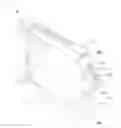
FIG. 1 is an isometric view of an electronic device with a support assembly in a first state, in accordance with an embodiment.
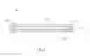
FIG. 2 is a cross-sectional view of the electronic device of FIG. 1, along line
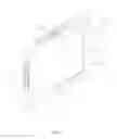
FIG. 3 is similar to FIG. 1, but showing the support assembly in a second state.
DETAILED DESCRIPTION
Referring to FIGS. 1-3, an exemplary embodiment of an electronic device 1 is illustrated. The electronic device 1 can be a tablet computer, a digital photo frame, etc.
The electronic device 1 includes a main body 10 and a support assembly 20 including four support components 21. Each support component 21 is arranged at one side of the main body 10. Each support component 21 includes a first arm 30 and a second arm 40, which are connected to each other and can rotate and slide relative to each other.
When the support assembly 20 is not in use, the support components 21 abut against one side of the main body 10, thereby protecting the electronic device 1 (see FIGS. 1-2). When the support assembly 20 is in use, the first and second arms 30, 40 of two opposite support components 21 are rotated to an angled state, and can support the main body 10 (see FIG. 3).
Referring to FIG. 3, a first end portion 301 of the first arm 30 is rotatably connected to one end of a side of the main body 10. A second end portion 302 extending from an end of the first arm 30 is rotatably connected to a pin 50. The second arm 40 defines a sliding groove 401 and includes a third end portion 402 rotatably connected to the other end of the side of the main body 10. The pin 50 is movably received in the sliding groove 401 and can slide in the sliding groove 401. The main body 10, the pin 50, and the first and second arms 30, 40 form a linkage bar mechanism.
When not in use, the first and second arms 30, 40 are pushed to abut against the main body 10. To use the support assembly 20, a user can select two opposite support components 21 according to a desired orientation of the electronic device 1, such as portrait or landscape, and push the selected support components 21, so that the pin 50 slides in the sliding groove 401 away from the third end portion 402 until a desired angle is formed between the first and second components 30, 40 as shown in FIG. 3. In the embodiment, the first and second arms 30 and 40 rotate in a plane perpendicular to the front surface of the main body 10. The two support components 21 thus form two support legs to support the main body 10. In the embodiment, the pin 50 can be retained at a desired position by friction between the pin 50 and the interior of the sliding groove 401. To adjust the angle between the main body and a support surface (i.e., desktop), the user can push the first and second arms 30, 40, sliding the pin 50, until a desired angle is obtained.
Referring also to FIG. 2, the first and second arms 30, 40 of each support component 21 cooperatively define a receiving groove 210 to receive one side of the main body 10. Therefore, the four support components 21 can protect the electronic device 1 from being damaged such as when accidentally dropped. In the embodiment, at least the portions of the support component 21 defining the receiving grooves 210 are made of rubber or other flexible material, so that the components 21 can firmly sandwich the sides of the main body 10 in the first state as shown in FIG. 1, but are flexible enough to be resiliently deformed when gripped and rotated with respect to the main body 10 to the second state as shown in FIG. 3.
Although the present disclosure has been described in accordance with the embodiments shown, one of ordinary skill in the art will readily recognize that there could be variations to the embodiments and those variations would be within the spirit and scope of the present disclosure. Accordingly, many modifications may be made by one of ordinary skill in the art without departing from the spirit and scope of the appended claims.
Claims
What is claimed is:1. An electronic device comprising:
a main body; and
a support assembly comprising four support components arranged around four sides of the main body, each support component comprising:
a first arm comprising a first end portion rotatably connected to one end of one of the four sides of the main body, and a second end portion extending from an end of the first arm;
a second arm comprising a third end portion rotatably connected to the other end of the side of the main body and defining a sliding groove; and
a pin connected to the second end portion of the first arm and slidably received in the sliding groove, wherein the pin is capable of being held in various positions by friction between the pin and the sliding groove, thereby allowing the support components to maintain at a desired orientation for supporting the main body.
2. The electronic device as described in claim 1, wherein each support component defines a receiving groove to receive a corresponding one of the four sides of the main body, allowing the support component to sandwich the corresponding side of the main body.
3. The electronic device as described in claim 2, wherein portions of the support components defining the receiving grooves are made of rubber.
4. The electronic device as described in claim 2, wherein the support components are made of rubber.
5. The electronic device as described in claim 2, wherein the first and the second arms of each support component cooperatively define the receiving groove.
Images & Drawings included:
Sources:
- United States Patent and Trademark Office - verify current appl. status at the USPTO↗
Similar patent applications:
- » 20160028862
Handheld electronic device, support assembly, and support assembly fabricating method - » 16023088
Adjustable electronic device support assembly - » 20150011271
Handheld electronic device, support assembly, and support assembly fabricating method - » 20180345874
Portable electronic device support assembly - » 20150366090
Wire controlled support assembly and electronic device including the same - » 20130075550
Supporting assembly for electronic device - » 20120325986
SUPPORTING ASSEMBLY FOR ELECTRONIC DEVICE - » 15921675
Systems and methods relating to support assemblies that support electronic devices - » 20120261305
ELECTRONIC DEVICE WITH SUPPORT ASSEMBLY - » 20190186683
Supporting assembly and electronic device using the same
Recent applications in this class:
- » 20250283571 2025-09-11
MOVABLE DISPLAY DEVICE - » 20250224072 2025-07-10
ADJUSTABLE CAMERA MOUNT - » 20250189071 2025-06-12
Stabilizing Joint for a Fan - » 20250180154 2025-06-05
Platform Rocker and Motions Performed Therewith - » 20250164062 2025-05-22
MOUNTING DEVICE FOR MOUNTING A CAMERA AND METHOD FOR ORIENTING A CAMERA - » 20250146615 2025-05-08
Tool Support Device - » 20250129880 2025-04-24
ADJUSTMENT HOOK ASSEMBLY AND METHOD OF FIXING AUDIOVISUAL DEVICE TO AUDIOVISUAL STAND - » 20250084957 2025-03-13
ATTACHMENT BASE FOR MOUNTING HARDWARE - » 20250075846 2025-03-06
Supporting Arm - » 20250052362 2025-02-13
TOOL-FREE ADJUSTABLE-TORQUE STAND SYSTEM
Recent applications for this Assignee:
- » 20250218287 2025-07-03
METHOD OF GENERATING AND PROMPTING TRAFFIC INFORMATION, AND ROADSIDE DEVICE THEREOF - » 20250178535 2025-06-05
METHOD FOR CONSTRUCTING 3D PANORAMIC VIEW MODEL, VEHICLE-MOUNTED DEVICE, AND STORAGE MEDIUM - » 20250074444 2025-03-06
METHOD FOR EARLY WARNING A BLIND AREA, ELECTRONIC DEVICE AND STORAGE MEDIUM - » 20240416754 2024-12-19
DISPLAY CONTROL DEVICE, DISPLAY EQUIPMENT, AND VEHICLE EMPLOYING DEVICE - » 20240411051 2024-12-12
Light-emitting device array and optical transceiver system having the same - » 20240324114 2024-09-26
DISPLAY CONTROL DEVICE AND VEHICLE EMPLOYING DEVICE - » 20240295957 2024-09-05
METHOD FOR CONTROLLING ELECTRONIC DEVICE, ELECTRONIC DEVICE AND COMPUTER STROAGE MEDIUM EMPLOYING METHOD - » 20240257357 2024-08-01
METHOD FOR DETECTING OBSTACLES, ELECTRONIC DEVICE, AND STORAGE MEDIUM - » 20240203133 2024-06-20
LANE LINE RECOGNITION METHOD, ELECTRONIC DEVICE AND STORAGE MEDIUM - » 20240194999 2024-06-13
Robot using limiting device for locking battery