Light module and optical lens for the light module
US20120294013A1
2012-11-22
13/109,796
2011-05-17
✅ Patent granted
US 8,708,527 B2
2014-04-29
-
-
Thomas Sember
Tracy M. Heims | Apex Juris, PLLC
2031-06-19
Abstract:
A light module includes a light source and an optical lens. The light source emits light to the optical lens. The light source is a single unit and has a parallelizing surface, a first plane, a wave surface, and a second plane in sequence. The light source emits light to the optical lens and through the parallelizing surface, the first plane, the wave surface, and the second plane in sequence to form a parallel linear light.
Assignee:
- ASIA OPTICAL CO., INC. 473 🇹🇼 Taichung, Taiwan
- ASIA OPTICAL CO., INC. 13 🇹🇼 Taichung City, Taiwan
Applicant:
Interested in similar patents?
Get notified when new applications in this technology area are published.
Classification:
G02B5/0278 » CPC main
Optical elements other than lenses; Diffusing elements; Afocal elements characterized by the use used in transmission
G02B5/0215 » CPC further
Optical elements other than lenses; Diffusing elements; Afocal elements characterised by the diffusing properties the diffusion taking place at the element's surface, e.g. by means of surface roughening or microprismatic structures the surface having a regular structure
G02B19/0014 » CPC further
Condensers, e.g. light collectors or similar non-imaging optics characterised by the optical means employed having refractive surfaces only at least one surface having optical power
G02B19/0061 » CPC further
Condensers, e.g. light collectors or similar non-imaging optics characterised by the use for use with a light source the light source comprising a LED
G02B27/0927 » CPC further
Optical systems or apparatus not provided for by any of the groups -; Beam shaping, e.g. changing the cross-sectional area, not otherwise provided for Systems for changing the beam intensity distribution, e.g. Gaussian to top-hat
G02B3/00 IPC
Simple or compound lenses
F21V5/04 IPC
Refractors for light sources of lens shape
Description
BACKGROUND OF THE INVENTION
1. Field of the Invention
The present invention relates generally to an optical device, and more particularly to a light module capable of changing the light into linear and parallel light and an optical lens for the light module.
2. Description of the Related Art
In present days, the touch panels and the touch systems, which provide user to operate image directly, are more and more popular in the market. Typically, there are two types of touch panels in the present market, resistive touch panels and capacitive touch panels. For a resistive touch panel, a pressure of finger touching the screen may cause a change of resistance to identify the location of the finger on the screen. However, the screen must be made of a flexible material that the surface of the screen will be worn and scratched for a time of use, and the speed of sense will slow down when one keeps pressing the same place. For a capacitive touch panel, it senses the natural current in human body when one touches the screen to identify the location of finger on the screen. However, the capacitive touch panel will not work when one wears glove or touches the screen by fingernail.
Recently, a new touch panel, photo-sensor type touch panel, is provided in the market. As shown in FIG. 1, a photo-sensor type touch panel is provided with two reflectors 110 to reflect laser rays of laser modules 120 crossing a screen 130 to be received by receivers 140. When one touches the screen 130 to block some laser rays, the specific receivers 140 will not receive the laser rays to identify the location of the finger. FIG. 2 shows another photo-sensor type touch panel, which has two micro-electromechanical systems (MEMS) to swing reflectors 210 to reflect linear laser rays of laser module 220 crossing a screen 230 to be received by receivers 240. For the same principle, when one touches the screen 240 to block some laser rays, the specific receivers 240 will not receive the laser rays to identify the location of the finger.
However, the photo-sensor type touch panel still has the following drawbacks:
1. It needs a space for the reflectors 210 and the MEMS that the photo-sensor type touch panel usually has a big size.
2. The MEMS is very expense, and it needs time to bootup that it slows down the time of sense of the photo-sensor type touch panel.
3. The use of reflectors needs the laser of great power that photo-sensor type touch panel needs more power.
In order to overcome the above drawbacks, an improved light module for the photo-sensor type touch panel, which provides a linear light without reflector, is provided. As shown in FIG. 3, Taiwan patent no. 1323769 taught such light module including an optical lens 300 and a lamp 330. The optical lens 300 includes a light collector 310 and a lenticular lens array 320 with a waved surface. 1323769 taught that such light module may be incorporated in street lamp or other types of lamp. However, the lamp 330 emits light to the light collector 310 and the lenticular lens array 320 in sequence to project a parallel and linear light, as shown in FIG. 4, which just meets the requirement of the photo-sensor type touch panel. However, the light module of 1323769 still has some drawbacks. The light from the lamp 310 will be transformed into parallel light by the light collector 310, and all of the parallel light will be reflected by the lenticular lens array 320 at a time. Therefore, the light couldn't get a better diffusion. In addition, the lenticular lens array 320 can't provide the light with a better diffusion as well because the crests and the troughs of the waved surface will concentrate the light.
In conclusion, the conventional light modules and the optical lens still have some places to be improved.
SUMMARY OF THE INVENTION
The primary objective of the present invention is to provide a light module to project a parallel linear light without reflector.
According to the primary objective of the present invention, a light module includes a light source and an optical lens. The light source emits light to the optical lens. The light source is a single unit and has a parallelizing surface, a first plane, a wave surface, and a second plane in sequence.
The light from the light source enters the optical lens via the parallelizing surface and leaves the optical lens via the first plane, and then the light enters optical lens again via the wave surface and leaves the optical lens via the second plane.
BRIEF DESCRIPTION OF THE DRAWINGS
FIG. 1 is a sketch diagram of the conventional photo-sensor type touch panel;
FIG. 2 is a sketch diagram of another conventional photo-sensor type touch panel;
FIG. 3 is a perspective view of the conventional light module to project linear light;
FIG. 4 is an illumination map of the conventional light module shown in FIG. 3;
FIG. 5 is a perspective view of a preferred embodiment of the present invention;
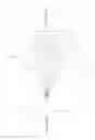
FIG. 6 is a sectional view in Y-Z plane and the light path of the preferred embodiment of the present invention;
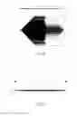
FIG. 7 is a sectional view in X-Z plane and the light path of the preferred embodiment of the present invention;
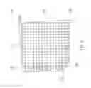
FIG. 8 is an illumination map in three dimensions of the preferred embodiment of the present invention; and
FIG. 9 is a sketch diagram of the shape of the light projected on the object from the preferred embodiment of the present invention.
DETAILED DESCRIPTION OF THE INVENTION
As shown in FIG. 5, a light module 1 of the preferred embodiment of the present invention is incorporated in a photo-sensor type touch panel. The light module 1 includes, from a light side to an object side, a light source 10 and an optical lens 20.
The light source 10 is a laser emitting device in the present invention to emit laser rays to the object side. The light source 10 may be LED, lamp, bulb, or other light emitting devices.
The optical lens 20 is a plastic lens made by injection molding. The optical lens 20, from the light side to the object side, has a parallelizing surface 21, a first plane 22, a wave surface 23, and a second plane 24. The parallelizing surface 21 is a convex plane. The wave surface 23 has flat portions at crests and troughs. The parallelizing surface 21 is formed at an end of the optical lens 20, and the second plane 24 is formed at an opposite end. The optical lens 20 has a cavity at a center thereof to form the first plane 22 and the wave surface 23 at opposite sidewalls of the cavity. Therefore, the laser from the light source 10 enters the optical lens 20 via the parallelizing surface 21 and leaves the optical lens 20 via the first plane 22 (enters the cavity), and then the laser will enter optical lens 20 again via the wave surface 23 and leave the optical lens 20 via the second plane 24.
As shown in FIG. 6 and FIG. 7, when the light source 10 emits laser, the laser will become parallel light when it projects through the parallelizing surface 21 and the first plane 22 and become linear light when it projects through the wave surface 23 and the second plane 24. Besides, the laser will be reflected twice or more when it projects through the parallelizing surface 21, the first plane 22, the wave surface 23, and the second plane 24 that the laser may be diffused to form a diffused, parallel and linear light. Therefore, as shown in FIG. 8, a diffusing angle of the light through the optical lens 20 of the present invention may reach 120 degrees that when the light arrives an object, which is 50 mm away from the light source 10, it is a transverse linear light with a width W between 0.1 mm and 0.5 mm.
In conclusion, the light module 1 of the present invention has a simple structure and a small size to provide a linear light with narrow width and great diffusing angle.
The advantages of the light module 1 of the present invention include:
1. There is no MEMS and reflector in the light module that may speed up the time of bootup and reaction.
2. The light module 1 of the present invention has a small size and may project thin parallel linear light that the photo-sensor touch panel incorporated with the light module 1 of the present invention may be made thinner and smaller.
3. The light source 10 only needs to provide the laser with regular power because there is no reflector involved that the photo-sensor touch panel incorporated with the light module 1 of the present invention may save more power.
It is noted that the light module 1 of the present invention may be incorporated in any field, except for photo-sensor touch panel, which needs parallel linear light. Therefore, any device which equipped with the light module 1 of the present invention, which projects light through the parallelizing surface 21, the first plane 22, the wave surface 23, and the second plane 24 in sequence still should be within the scope of the present invention.
The description above is a few preferred embodiments of the present invention. These equivalences of the present invention are still in the scope of claim construction of the present invention.
Claims
What is claimed is:1. A light module, comprising:
a light source for emitting light from a light side to an object side; and
an optical lens, which is a single unit, having a parallelizing surface, a first plane, a wave surface, and a second plane from the light side to a object side;
wherein the light from the light source enters the optical lens via the parallelizing surface and leaves the optical lens via the first plane, and then the light enters optical lens again via the wave surface and leaves the optical lens via the second plane.
2. The light module as defined in claim 1, wherein the light from the light source is transformed into a parallel light when it emits through the parallelizing surface and the first plane, and then is transformed into a linear light when it emits through the wave surface and the second plane.
3. The light module as defined in claim 1, wherein the wave surface has flat portions at crests and troughs.
4. The light module as defined in claim 1, wherein the parallelizing surface has a convex surface.
5. The light module as defined in claim 1, wherein the optical lens is made of plastic.
6. An optical lens, which is a single unit, comprising a parallelizing surface, a first plane, a wave surface, and a second plane in sequence, wherein the light enters the optical lens via the parallelizing surface and leaves the optical lens via the first plane, and then the light enters optical lens again via the wave surface and leaves the optical lens via the second plane.
7. The optical lens as defined in claim 6, wherein the light is transformed into a parallel light when it emits through the parallelizing surface and the first plane, and then is transformed into a linear light when it emits through the wave surface and the second plane.
8. The optical lens as defined in claim 6, wherein the wave surface has flat portions at crests and troughs.
9. The optical lens as defined in claim 6, wherein the parallelizing surface has a convex surface.
Images & Drawings included:


Sources:
- United States Patent and Trademark Office - verify current appl. status at the USPTO↗
Similar patent applications:
- » 20180306406
Optical lens, lighting module, and light unit comprising same - » 20200217463
Optical lens, lighting module and light unit having the same - » 20150062905
Optical lens, method for manufacturing the optical lens and light source module incorporating the optical lens - » 20160201875
Optical lens, light emitting module and light unit having the same - » 20170234507
Optical lens, light emitting module, and light unit including the same - » 20130002612
Photo-sensor type touch device and light module and optical lens for the photo-sensor type touch device - » 20120155092
Optical lens module and lighting apparatus having the same - » 20120051066
Optical lens, LED module having the optical lens, and lighting apparatus having the LED module - » 20130286657
OPTICAL LENS AND LIGHT SOURCE MODULE HAVING THE SAME - » 20120057354
Optical lens and light source module, and street lamp having the same
Recent applications in this class:
- » 20250208324 2025-06-26
DIFFUSER, LIGHT EMITTING DEVICE, AND SENSOR MODULE - » 20240411063 2024-12-12
Optical film and display device - » 20240219611 2024-07-04
Light adjustment module - » 20240069255 2024-02-29
MICROLENS ARRAY, DIFFUSION PLATE, AND ILLUMINATION DEVICE - » 20230393313 2023-12-07
Sensor lens assembly - » 20230375758 2023-11-23
MEANS FOR SUPPORTING A DEPLOYABLE WIRELESS FRESNEL LENS - » 20230266511 2023-08-24
DIFFUSED LIGHT CONTROL SHEET AND DIFFUSED LIGHT IRRADIATION DEVICE - » 20230228920 2023-07-20
Composite optical film - » 20230068198 2023-03-02
OPTICAL DIFFUSER - » 20230062823 2023-03-02
Optical film for MiniLED backlight module and method for preparing same
Recent applications for this Assignee:
- » 20240361104 2024-10-31
AIMING DEVICES AND METHODS THEREOF - » 20230288683 2023-09-14
Optical system - » 20230194256 2023-06-22
Range finder and lens assembly for display thereof - » 20230047206 2023-02-16
Lens device capable of operation of multi-magnifications, optical zoom in high magnification, and miniaturization of the lens module thereof - » 20230018568 2023-01-19
Lens Device - » 20220413278 2022-12-29
Compensating mechanism - » 20220390812 2022-12-08
Lens driving devices and driving methods thereof - » 20220390722 2022-12-08
WIDE-ANGLE LENS ASSEMBLY - » 20220373296 2022-11-24
Sight and compensating mechanism thereof - » 20220357564 2022-11-10
Optical device