Fan control circuit
US20120301321A1
2012-11-29
13/228,462
2011-09-09
✅ Patent granted
US 8,757,985 B2
2014-06-24
-
-
Devon Kramer | Lilya Pekarskaya
Novak Druce Connolly Bove + Quigg LLP
2031-12-23
Abstract:
A fan control circuit of a computer includes a fan interface connected to a connector of a fan, a fan controller and an electronic switch chip. The fan controller outputs a pulse width modulation (PWM) signal to the fan interface to control the operation of the fan, and includes a general purpose input/output (GPIO) interface to output a voltage control signal to the electronic switch chip to switch the electronic switch chip on or off. The voltage control signal is at a low level at the start up moment of the computer, and thus does not turn on the fan via the electronic switch chip. After a preset delay period, the voltage control signal becomes a high-level signal under the control of the fan controller so that the fan interface receives the PWM signal.
Inventors:
- GUO-YI CHEN 43 🇨🇳 Shenzhen City, China
- KANG WU 71 🇨🇳 Shenzhen City, China
- KANG WU 123 🇨🇳 Shenzhen, China
- GUO-YI CHEN 71 🇨🇳 Shenzhen, China
Assignee:
- HON HAI PRECISION INDUSTRY CO., LTD. 12,833 🇹🇼 Tu-Cheng, Taiwan
- HONG FU JIN PRECISION INDUSTRY (ShenZhen) CO., LTD 200 🇹🇼 Shenzhen City, Taiwan
- HON HAI PRECISION INDUSTRY CO., LTD. 10,014 🇹🇼 New Taipei, Taiwan
- HONG FU JIN PRECISION INDUSTRY (ShenZhen) CO., LTD. 2,585 🇨🇳 Shenzhen, China
Applicant:
Interested in similar patents?
Get notified when new applications in this technology area are published.
Classification:
F04B49/00 IPC
Control, e.g. of pump delivery, or pump pressure of, or safety measures for, machines, pumps, or pumping installations, not otherwise provided for, or of interest apart from, groups -
H05K7/20209 » CPC main
Constructional details common to different types of electric apparatus; Modifications to facilitate cooling, ventilating, or heating using a gaseous coolant in electronic enclosures Thermal management, e.g. fan control
H05K7/20209 » CPC main
Constructional details common to different types of electric apparatus; Modifications to facilitate cooling, ventilating, or heating using a gaseous coolant in electronic enclosures Thermal management, e.g. fan control
G06F1/206 » CPC further
Details not covered by groups - and; Constructional details or arrangements; Cooling means comprising thermal management
Y02D10/00 » CPC further
Energy efficient computing, e.g. low power processors, power management or thermal management
Y02D10/00 » CPC further
Energy efficient computing, e.g. low power processors, power management or thermal management
F04B49/06 IPC
Control, e.g. of pump delivery, or pump pressure of, or safety measures for, machines, pumps, or pumping installations, not otherwise provided for, or of interest apart from, groups - Control using electricity
Description
CROSS-REFERENCE TO RELATED APPLICATIONS
This application is related to a U.S. patent application entitled “FAN CONTROL CIRCUIT,” with the same assignee as the instant application and with the Attorney Docket No. US40026. The disclosure of the above identified application is incorporated herein by reference.
BACKGROUND
1. Technical Field
The present disclosure relates to a fan control circuit.
2. Description of Related Art
Many servers include multiple fans, which begin to rotate at full speed at the moment of the server being started up. The power consumed by the interior components of the server, such as motherboards, hard disk drives and fans, can be up to a thousand kilowatts at the start up moment, which may cause instability in the power supply to the server, and high power consumption. Delay circuitry can be used to make the fans start operating after a preset delay period, however, many delay circuits include multiple extra components, which results in high cost.
BRIEF DESCRIPTION OF THE DRAWING
Many aspects of the embodiments can be better understood with reference to the drawing. The components in the drawing are not necessarily drawn to scale, the emphasis instead being placed upon clearly illustrating the principles of the present embodiments.
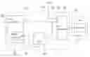
The drawing is a block diagram of an exemplary embodiment of a fan control circuit connected to a fan via a fan connector.
DETAILED DESCRIPTION
The disclosure, including the accompanying drawing, is illustrated by way of example and not by way of limitation. It should be noted that references to “an” or “one” embodiment in this disclosure are not necessarily to the same embodiment, and such references mean at least one.
Referring to the figure, an exemplary embodiment of a fan control circuit 100 of a computer includes a fan controller 90, an electronic switch chip 40 and a fan interface 30 for connecting with a connector 25 of a fan 20.
The terminals of the fan interface 30 include a power pin 15 and a control pin 14. A power supply VCC is connected to the power pin 15 of the fan interface 30 to provide voltage for the operation of the fan 20.
The fan controller 90 includes a rotational speed control pin 16 which outputs a pulse width modulation (PWM) voltage, and a general purpose input/output (GPIO) interface 95 with a control pin 12 for outputting a control signal. The rotational speed control pin 16 is connected to the control pin 14 of the fan interface 30 to transmit the PWM signal to the fan interface 30 to control the operation of the fan 20. The voltage control signal at the control pin 12 of the electronic switch chip 40 is at a low level at the moment of the computer being started up, and after a preset delay period, becomes a high level signal under the control of the fan controller 90.
The electronic switch chip 40 (e.g. an NC7SV125P5X_DS chip) includes an enable terminal OE, a signal input terminal A, and a signal output terminal Y. The enable terminal OE and the signal input terminal A of the electronic switch chip 40 are connected to the control pin 12 of the GPIO interface 95, and the signal output terminal Y is coupled to the rotational speed control pin 16 of the fan controller 90. The electronic switch chip 40 is turned on only when the enable terminal OE of the electronic switch chip 40 receives a low-level signal.
As the computer starts up, the power supply VCC provides a constant voltage to the power pin 15 of the fan interface 30, and the rotational speed control pin 16 of the fan controller outputs a constant PWM signal to the control pin 14 of the fan interface 30. At the same time, the control pin 12 of the GPIO interface 95 outputs a low-level signal to the input terminal A and to the enable terminal OE of the electronic switch chip 40. The electronic switch chip 40 is turned on, and the low-level signal from the signal input terminal A of the electronic switch chip 40 is transmitted to the rotational speed control pin 16 of the fan controller 90 via the signal output terminal Y of the electronic switch chip 40. The PWM signal being received at the control pin 14 of the fan interface 30 simultaneously with the low-level signal from the output terminal Y of the electronic switch chip 40 sinks the voltage at the control pin 14 of the fan interface 30 to approximately zero, which leaves the fan 20 turned off.
After a preset delay period, the voltage control signal at the control pin 12 of the GPIO interface 95 becomes a high-level signal under the control of the fan controller 90. The resulting high-level signal is then sent to the enable terminal OE to turn off the electronic switch chip 40. The control pin 14 of the fan interface 30 receives a PWM signal from the rotational speed control pin 16 of the fan controller 90 to start and control the speed of operation of the fan 40.
The foregoing description of the exemplary embodiments of the disclosure has been presented only for the purposes of illustration and description and is not intended to be exhaustive or to limit the disclosure to the precise forms disclosed. Many modifications and variations are possible. The embodiments are described in order to explain the principles of the disclosure and their practical application so as to enable others of ordinary skill in the art to utilize the disclosure, with such various modifications as are suited to the particular use contemplated. Alternative embodiments will become apparent to those of ordinary skills in the art to which the present disclosure pertains without departing from its spirit and scope. Accordingly, the scope of the present disclosure is defined by the appended claims rather than by the foregoing description and the exemplary embodiments described therein.
Claims
What is claimed is:1. A fan control circuit of a computer, the fan control circuit comprising:
a fan interface connected to a connector of a fan of the computer, and comprising a first control pin;
an electronic switch chip comprising an enable terminal, a signal input terminal and a signal output terminal, wherein the electronic switch chip is turned on when the enable terminal receives a low-level voltage control signal; and
a fan controller comprising a general purpose input/output (GPIO) interface and a rotational speed control pin connected to the first control pin of the fan interface and the signal output terminal of the electronic switch chip, the GPIO interface comprising a second control pin connected to the signal input terminal and the enable terminal of the electronic switch chip for outputting a control signal, wherein the control signal is at a low level at the moment of the computer being started up, the electronic switch chip is turned on, and transmits the low-level signal to the rotational speed control pin of the fan controller and the first control pin of the fan interface, thereby the fan is not turned on; after a preset delay period of time after the computer is started up, the voltage control signal at the second control pin of the GPIO interface becomes a high-level signal under the control of the fan controller, the electronic switch chip is turned off, the rotational speed control pin of the fan controller outputs a pulse width modulation (PWM) signal to the first control pin of the fan interface to control the operation of the fan.
Images & Drawings included:
Sources:
- United States Patent and Trademark Office - verify current appl. status at the USPTO↗
Similar patent applications:
- » 15725359
Fan control circuit and fan control method - » 20200146179
Fan control circuit and fan control system - » 18613722
Fan and lamp control circuit, fan and lamp device, and fan and lamp system - » 20090009122
Fan motor speed control circuit, fan apparatus, and electronic apparatus - » 20210315129
Fan control circuit with temperature compensation and method of controlling fan - » 20100014843
Fan controlling circuit - » 20100127651
Fan controlling circuit - » 20090102406
Motor control circuit, fan motor, electronic device, and notebook personal computer - » 9949764
Fan control circuit and package - » 20090278487
Fan control circuit
Recent applications in this class:
- » 20250275084 2025-08-28
TEMPERATURE MANAGING SYSTEM AND TEMPERATURE MANAGING METHOD - » 20250240914 2025-07-24
Temperature-controlled enclosure for containing temperature-sensitive electronic and/or telecommunications equipment - » 20250234481 2025-07-17
AUDIO RECORDING APPARATUS, IMAGE CAPTURING APPARATUS, CONTROL METHOD, AND STORAGE MEDIUM - » 20250212360 2025-06-26
ELECTRONIC DEVICE AND METHOD FOR DISSIPATING HEAT FROM PLURALITY OF HEAT SOURCES - » 20250169028 2025-05-22
FAN CONTROL FOR ELECTRONIC DISPLAY ASSEMBLIES - » 20250169027 2025-05-22
METHODS AND APPARATUS TO ENHANCE COOLING OF COMPUTING DEVICES - » 20250169026 2025-05-22
FAN SPEED CONTROL METHOD - » 20250151227 2025-05-08
CONTROL DEVICE AND NON-TRANSITORY COMPUTER-READABLE STORAGE MEDIUM - » 20250142768 2025-05-01
ROTATABLE FAN OUTLET FOR DIFFERENT USER SCENARIOS - » 20250126743 2025-04-17
Heat management in network switch
Recent applications for this Assignee:
- » 20250218287 2025-07-03
METHOD OF GENERATING AND PROMPTING TRAFFIC INFORMATION, AND ROADSIDE DEVICE THEREOF - » 20250178535 2025-06-05
METHOD FOR CONSTRUCTING 3D PANORAMIC VIEW MODEL, VEHICLE-MOUNTED DEVICE, AND STORAGE MEDIUM - » 20250074444 2025-03-06
METHOD FOR EARLY WARNING A BLIND AREA, ELECTRONIC DEVICE AND STORAGE MEDIUM - » 20240416754 2024-12-19
DISPLAY CONTROL DEVICE, DISPLAY EQUIPMENT, AND VEHICLE EMPLOYING DEVICE - » 20240411051 2024-12-12
Light-emitting device array and optical transceiver system having the same - » 20240324114 2024-09-26
DISPLAY CONTROL DEVICE AND VEHICLE EMPLOYING DEVICE - » 20240295957 2024-09-05
METHOD FOR CONTROLLING ELECTRONIC DEVICE, ELECTRONIC DEVICE AND COMPUTER STROAGE MEDIUM EMPLOYING METHOD - » 20240257357 2024-08-01
METHOD FOR DETECTING OBSTACLES, ELECTRONIC DEVICE, AND STORAGE MEDIUM - » 20240203133 2024-06-20
LANE LINE RECOGNITION METHOD, ELECTRONIC DEVICE AND STORAGE MEDIUM - » 20240194999 2024-06-13
Robot using limiting device for locking battery