Orthopedic aid
US20120311756A1
2012-12-13
13/134,663
2011-06-13
Abstract:
An orthopedic aid formed by shin shell positioned upon an underlying pad which extends beyond the shell to the knee joint and an anti-slip member is positioned upon the shell which is held in place on the shin.
Interested in similar patents?
Get notified when new applications in this technology area are published.
Classification:
A41D13/065 » CPC main
Professional, industrial or sporting protective garments, e.g. surgeons' gowns or garments protecting against blows or punches protecting only a particular body part; Knee or foot Knee protectors
A41D13/0568 » CPC further
Professional, industrial or sporting protective garments, e.g. surgeons' gowns or garments protecting against blows or punches protecting only a particular body part; Protector fastening, e.g. on the human body with releasable fastening means with straps
A41D13/06 IPC
Professional, industrial or sporting protective garments, e.g. surgeons' gowns or garments protecting against blows or punches protecting only a particular body part Knee or foot
Description
CURRENT U.S. CLASS
Current International Class
| References |
| U.S. Patent Documents |
| 830,661 | September 1905 | Greshnam | |
| 967,004 | August 1910 | Ehikian | |
| 1,055,040 | March 1913 | Herron et al. | |
| 1,090,446 | March 1914 | Boynton | |
| 1,486,308 | March 1924 | Shook | |
| 1,571,088 | January 1926 | Buchanan | |
| 2,195,817 | April 1940 | Johnson | |
| 2,418,197 | April 1947 | Sherer | |
| 2,626,394 | January 1953 | Davis | |
| 2,759,189 | August 1956 | Cole | |
| 3,465,365 | September 1969 | Jones et al. | |
| 3,587,572 | June 1971 | Evans | |
| 3,728,736 | April 1973 | Pugh | |
| 3,735,419 | May 1973 | Byrd | |
| 3,772,704 | November 1973 | Carbonneau | |
| 4,116,236 | September 1978 | Albert | |
| 4,287,885 | September 1981 | Applegate | |
| 4,493,316 | January 1985 | Reed et al. | |
| 4,507,804 | April 1985 | Consigny | |
| 4,681,012 | July 1987 | Stelma et al. | |
| 4,686,969 | August 1987 | Scott | |
| 4,692,946 | September 1987 | Jurga | |
| D297178 | August 1988 | Jurga | |
| 4,893,355 | January 1990 | Ritter | |
| 5,031,240 | July 1991 | Nierhaus | |
| 5,301,370 | April 1994 | Henson | |
| 5,334,135 | August 1994 | Grim et al. | |
| 5,347,657 | September 1994 | Unsell | |
| 5,500,955 | March 1996 | Gongea | |
| 5,524,292 | June 1996 | Hargens | |
| 5,537,689 | July 1996 | Dancyger | |
| 5,658,243 | August 1997 | Miller et al. | |
| 5,711,029 | January 1998 | Visco et al. | |
| 5,760,868 | June 1998 | Jannard et al. | |
| 5,794,261 | August 1998 | Hefling | |
| 6,128,779 | October 2000 | Goldsmith et al. | |
| 6,223,350 | May 2001 | McFarlane | |
| 6,253,376 | July 2001 | Ritter | |
| 6,279,160 | August 2001 | Chen | |
| D473977 | April 2003 | Lesosky | |
| 6,584,616 | July 2003 | Godshaw et al. | |
| 6,820,279 | November 2004 | Lesosky | |
| 6,832,390 | December 2004 | Kleinert et al. | |
| 7,181,770 | February 2007 | Godshaw | |
| 7,376,978 | May 2008 | Godshaw | |
| 7,451,493 | November 2008 | Godshaw | |
| 2004/0111780 | June 2004 | Lesosky | |
OTHER REFERENCES
The Home Deport; Ad #63693/63698; May-June 2004; Professional I-Gel Kneepads, Item No. 433003; Rubbermaid Professional Kneepads, No. 9H10; Knee-Pad—Black Gel Cap, Item No. 0CC121; Bucket Boss Air-Gel 2 Kneepads, Item No. 171927. Professional Gel Kneepads, Product No. G340; Black Diamond Telekneesis Kneepad. Dainese Women's Knee Guard; Dainese: Snow Elbow Guard Evo, Article No. 17667; Knee Pro Knee Armor by Dainese; BlackHawk Hellstorm Advanced Tactical Kneepads w/Rivet Capo, Mechanix Standard Knee Pad, Item No. MKP05-600; Mechanix Deluxe Team Issue Knee Pad, Item No. MKPP-05-700; Freedom® Comfort™ OAKneww Orthosis, SKU 64316; MX-2 Knee Brace, Adult Left Model Nos. 6404-21-530, 6404-22-530; Motocross kneepads, February 2007; The Knee Pro Ultra Flex III™
BACKGROUND OF THE INVENTION
In a principal aspect, the present invention relates to protective constructions and, more particularly, to an appliance which protects the knee of a user, such as a workman.
It is common practice to provide protective knee pads for various individuals; for example, construction workers, mechanics, sportsmen, athletes, and others who find it necessary to protect their knees as a result of their work or activities, particularly when kneeling on a hard surface. Utilization of protective knee pads placed on or around the knee for use when kneeling on hard surfaces is thus a common practice and, in some instances, a requirement in order to effectively engage in a trade or craft. Various constructions are available and they typically comprise a rigid case or outer shell which is padded on the inside surface, is shaped to be fitted over the knee and includes attachment straps for retention on or over the knee. None of these devices are particularly satisfactory, especially for persons who have had knee surgery and knee replacement.
Typical constructions are the subject of various prior patents and applications including U.S. Pat. No. 6,584,616 B2 issued Jul. 1, 2003 and U.S. Pat. No. 6,223,350 for a Molded Construction, U.S. Pat. No. 5,031,240 for a Knee Pad; U.S. Pat. No. 5,794,261 for a Protective Joint Guard; U.S. Pat. No. 5,537,689 for a Protective Knee Pad Having a Single Piece Cupping Means and Stitch Receiving Groove; U.S. Pat. No. 5,500,955 for a Knee Pad for Athletes; U.S. Design Pat. No. D473,977 for a Knee Pad; and U.S. Patent Publication No. US2004/0111780 for a Knee Pad.
One problem associated with the use of knee pads relates to a situation where the pad will tend to slip or move while the workman or individual using the pad is changing positions; for example, moving from a standing to a kneeling position. To overcome this problem, various types of strap constructions have been proposed. While such solutions have their benefits, they are not necessarily acceptable in all circumstances.
Another problem often observed with protective knee pads for workmen and others is associated with the shape or form of the knee pad. Often the knee pad, as a result of its configuration, will tend to bind or cut into the shin or thigh of a workman when moving or when changing from one position to another. These, among other issues, have been considered vexing to various workmen and others needing protective devices.
In addition, all known knee pads do not provide suitable protection for the knee. It is, therefore, a primary objective of the invention to provide suitable protection for the knee of a user.
SUMMARY OF THE INVENTION
In accomplishing the foregoing and related objectives, the invention provides a protective appliance formed by a generally rigid shell including a concave interior and a convex exterior and connection for positioning the shell on the shim below the knee joint.
The appliance can include a pad on the concave interior of the shell with the pad configured to extend to the knee joint when said shell is connected on the shim below the knee joint.
A skid-resistant cover on the convex exterior of the shell can be configured to fit on the shin below the knee joint, and the cover can extend within the outer periphery of the shell.
Side straps can be attached to the shell which is formed with a concave interior and a convex exterior, a pad on the concave interior and configured to fit on the shin below the knee joint of a user and with a pad assembly extending to the knee joint.
In accordance with one aspect of the invention the upper and lower portions of the shell are formed with curved configurations, and the cover extends within the outer periphery of the shell to which side straps are attached.
In accordance with another aspect of the invention an attachment member of the appliance is in the form of a flexible strap having a left hand section and a right hand section, which sections can overlap whereby when the shell is attached to the leg of an individual, the flexible strap remains disposed behind the shell and attached pad assembly. The left hand strap section and right hand strap section are generally straight strap sections respectively joinable together.
In accordance with a further aspect of the invention, the shell is oval-shaped and the cover also is oval shaped and overlies the shell and is adhered to it. The pad also can be oval shaped, with the combination of the shell and cover asymmetrically disposed thereon.
In a method of the invention for protecting a knee, the steps include (a) applying a generally rigid shell including a concave interior and a convex exterior at the of the fibula portion of the leg; and (b) positioning the shell at the front of the fibula of a user below the patella; thereby to permit a person to kneel on the fibula without injury or pain to the patella.
The method further includes the step of kneeling on the fibula with said shell in place; employing a skid-resistant cover on the convex exterior of the shell; and employing a pad on the concave interior of the shell
The method further includes the step of positioning the pad asymmetrically under the rigid shell, and fastening said shell to the fibula by straps.
In a method of the invention for manufacturing a protective appliance, the steps include: (a) providing an oval shell having a concave interior for engaging the fibula region of a leg and a convex exterior; (b) attaching a skid-resistant, elastomeric cover to the convex exterior; and (c) attaching a pad to the concave interior.
The method further includes asymmetrically positioning the shell on the pad and positioning the pad under the shell to have a bill portion that extends beyond the patella when the shell is positioned on the fibula of a user.
The method also includes providing the cover as a non-skid black rubber, providing the shell as a hard plastic and providing the pad with Velcro™ straps. Thus, it is an object of the invention to provide improved knee protector constructions.
It is a further object of the invention to provide a knee protector construction with a convex knee protection shell in combination with an attached or attachable thigh element or construct or member.
Another object of the invention is to provide a knee protector construction which will facilitate simultaneous protection of the lower thigh, the knee and the upper shin of a workman or user.
Another object of the invention is to provide a knee protector construction wherein a thigh member protects the knee. A further object of the invention is to provide a knee protector construction which is rugged, economical, easy to use, lightweight and capable of use for protection of a wide variety of knee sizes and shapes.
These and other objects, advantages and features of the invention will be set forth in the detailed description which follows.
BRIEF DESCRIPTION OF THE DRAWINGS
In the detailed description which follows reference will be made to the drawing comprised of the following Figures:
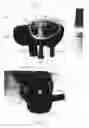
FIG. 1 is a photograph of a first embodiment of the invention showing the NU KNEE™ Appliance of the invention suspended from a support rod;
FIG. 1A is a color photograph of the NU KNEE™ Appliance of FIG. 1;
FIG. 2 is a view of the NU KNEE™ Appliance FIG. 1 rotated 90 degrees;
FIG. 2A is a color photograph of the NU KNEE™ Appliance of FIG. 2;
FIG. 3 is a further side view of the NU KNEE™ Appliance of FIG. 1;
FIG. 3A is a color photograph of the NU KNEE™ Appliance of FIG. 3
FIG. 4 is a side view showing the Appliance of FIG. 1 attached to the fibula of a user;
FIG. 4A is a color photograph of the knee protector of FIG. 4;
FIG. 5 is a side view drawing of the knee protector construction of FIG. 1;
FIG. 5A is a side view of the protector without padding or cover;
FIG. 6 is a diagram of a human skeleton with the knee protector attached to the right shin;
FIG. 7 is a photographic enlargement of FIG. 4 showing how the weight of a kneeling person using the invention is transferred from the knee to the knee protector.
FIG. 8A is scale drawing of a top view of the knee-protection shell of the invention.
FIG. 8B is a top view of the knee-protection shell of FIG. 8A; and
FIG. 8C is a perspective view of the knee-protection shell of FIGS. 8A and 8B.
DETAILED DESCRIPTION OF EMBODIMENTS OF THE INVENTION
With reference to the drawings, FIG. 1 shows a first embodiment 10 of the invention positioned on a pole P. The embodiment 10 includes a generally rigid-formed knee protection shell 11, with an outer face 12 and a peripheral edge 13. The shell 11 is partially covered by a skid-resistance cover 14, and the shell 11 is positioned on a pad 15 with a frontal bill 15-b that can extend to the patella of a user when the shell 11 is positioned relative to the fibula of a user just below the knee-cap or patella.
The shell 11 may have any number of desired forms. It may be generally convex. It may include a surface comprised of various flat sections, separated by a slot or depression The configuration of the shell provides a surface wherein protection of the knee of a workman or user is facilitated. Thus, the shell may be as illustrated, or it may be configured in some other manner that is desired to facilitate utility.
The shell 11 includes an attached inner or inside padded layer or pad 15 with attached flexible straps 16-1 and 16-2. The straps 16-1 and 16-2 are attached respectively to the opposite, lateral side or peripheral edges of the pad 15 and may be fitted and engaged around the back side of a fibula or lower leg or shin to hold the combination of shell 11 and padding 15 in place. The straps 16-1 and 16-2 can be wider or have a greater dimension where they connect to the shell 11 and padding or pad 15. The outer ends of the straps can be narrower in construction than the portion attached to the shell 11 and or padding 15 to facilitate placement on the leg below the knee not to bind against the skin on the back side of the knee of a worker when fastened together by a Velcro™ Attachment or by a hook and loop fastening mechanism, for example.
The shell 11 is oval and has a dome and can include first and second integrally molded or formed extensions or arms positioned respectively on opposite sides of the shell 11 and extending generally transverse to the front face of shell 11. Such arms can be equally sized and have substantially identical shapes. They are positioned to be generally below the knee joint of a person using the appliance. Such alignment is considered important for assurance of comfort and functionality of the construction when fastened in position below the knee.
The color photograph of FIG. 1A shows in further detail the structure of the knee protector in FIG. 1;
In FIG. 2 the knee protector of FIG. 1 has bee rotated 90 degrees so that the bill portion of the underlying pad that approached the knee when the protector is attached to the shin below the knee is at the bottom of the Figure.
The color photograph of FIG. 2A shows in further detail the structure of the knee protector in FIG. 2.
In FIG. 3 the protector of FIG. 1 has been elevated and turned to give a better side view of the protector
The color photograph of FIG. 3A shows in further detail the structure of the knee protector in FIG. 2.
FIG. 4 shows one attachment of the protector of FIG. 1 to the fibula of a user.
FIG. 4A is a color photograph of FIG. 4
FIG. 5 shows side view details of a tested embodiment 50 of the knee protector of the invention. The shell 51 is of dark brown hard plastic and has a black skid-resistant rubber cover 52 that has a maximum height of ¼ inch, a width of about 2 inches and a length of about 4 inches. The bill portion 55-b extends about 2¾ inches from the front of the shell 51, while the back of the pad 55 extends about 1 inch from the shell 51. The pad 55 has a thickness of about ⅝ inches and the overall height of the protector was about 3½ inches. The overall length was between 10½ inches and 11 inches. The shell has a height of about 3 inches and a length of about 6 inches. The Velcro™ tabs are shown attached to the pad but they may instead be attached directly to the shell.
FIG. 5A is a side view of the protector shell 51 of FIG. 5 without the pad 55, or cover 52. It may be attached directly to the fibula as a protector without the pad 55 or the skid resistant cover 52. It is configured as a shell that is adaptable for attachment to the fibula of a user.
FIG. 6 is a diagram of a human skeleton with the knee protector 50 attached to the right shin. As shown in FIG. 6, in anatomical terms, the lower leg is composed of five distinct parts: the knee joint, the shin, the calf, the ankle, and the foot. In terms of the general functions of the lower leg, all movement is initiated by either a flexion or an extension of the knee joint. Either movement will stimulate a corresponding action on the part of the calf muscles and an attached Achilles tendon. These structures are themselves attached to the flexor and extension muscles of the ankle and the foot, which govern how the foot will be moved. The entire process of knee action to foot position is not a continuum, progressing down the lower leg. It is an integrated, system-wide response to a stimulus transmitted by the brain to the central nervous system and simultaneously received at the nerve endings in the muscles of the lower leg.
Because the domed shell 11 or 51 of the invention is attached to the muscles associated with the fibula, it is believed that the pressure on those muscles when the user is in a kneeling position with the shell attached, permits muscular action in the kneeling position without pain or injury to the knee
FIG. 7 is a photographic enlargement of FIG. 4 showing how the weight of kneeling person using the invention has weight transferred from the knee to the knee protector.
As shown in FIG. 7, with the shell of the embodiment depicted in FIG. 1 protecting the knee, a workman may move into a kneeling position and have the shin protected by a hard shell, so that the knee becomes protected as well Additionally, the attachment of the shell 11 to the shin has the function of maintaining its position, so that it will not undesirably slip out of position upon movement of the workman. The straps fit around the lower leg. The straps fit below and behind the knee joint thereby enhancing comfortable use of the construction.
The hard outer shell 11 may be fabricated from a molded polymeric or rubberized material. The hard outer shell 11 includes a curved frontal end, middle section which rises to a dome, and rear end section which has a greater curvature than the frontal end.
The underlying pad 15 has a frontal section 15-a which is outwardly extending in the form of a duck bill to fit over the knee cap when the appliance is positioned on the upper shin below the knee cap.
In the top view scale drawing of FIG. 8A, the knee-protection shell 80 of the invention is shown without padding or a skid-resistant cover. The Shell 80 may be attached to the shin below the knee joint using the Velcro straps 81-r and 81-l, or the shell may be attached in any other suitable way. The shell 80 measures 6 and ½ inches from the upper edge 82-u to the lower edge 82-o, and has a dome 84 that rises about 1 and ½ inches above the right edge 83-r, extending about 5 inches to the left edge 83-l. The shell 80 also has a ⅛ inch rim 83 that encircles the shell. The monogram “NK” near the upper edge 82-u is an abbreviation for “NU KNEE” ™ Orthopedic Appliance.
A top view of the knee-protection shell 80 of FIG. 8A is shown in FIG. 8B, and a perspective view is shown in FIG. 8C.
The inventor has had knee surgery, and by using the invention has been able to kneel as shown in FIGS. 4 and 7. This allows him to do any kind of job that requires kneeling without injury to his knee.
The present invention is of particular use for persons who have had knee surgery or must avoid contact with the knee. It is to be noted that doctors who treat knee injuries generally recommend avoid knee contact wherever possible.
While there have been set forth various embodiments of the invention, along with a detailed description thereof, the invention is limited only by the claims and equivalents.
Claims
What is claimed:1. A method of producing a protective appliance comprising, in combination: a generally rigid shell including a concave interior and a convex exterior, and means for connecting said shell on the shim below the knee joint.
2. The method of claim 1 further including a pad on the concave interior of said shell with said pad configured to extend to the knee joint when said shell is connected on the shim below said knee joint.
3. The method of claim 1 further including a skid-resistant cover on the convex exterior of said shell which is configured to fit on the shin below the knee joint
4. The method of claim 3 wherein said cover extends within the outer periphery of said shell.
5. The method of claim 1 wherein a side strap is attached to said shell.
6. The method of claim 1 further including an attachment member comprising a flexible strap having a left hand section and a right hand section, which sections can overlap whereby when said shell is attached to the leg of an individual, the flexible strap remains disposed behind said shell and its attached pad assembly.
7. The method of claim 6 wherein the left hand strap section and right hand strap section are generally straight strap sections respectively joinable together.
8. The method of claim 1 wherein said shell is oval-shaped.
9. The method of claim 8 wherein said cover is oval shaped and overlies said shell.
10. The method of claim 1 wherein said pad is oval shaped with the combination of said shell and cover asymmetrically disposed on said pad.
11. A method of protecting a knee which comprises the steps of:
(a) applying a generally rigid shell including a concave interior and a convex exterior on the fibula portion of the leg
(b) positioning said shell at the front of the fibula below the patella, thereby to permit a person to kneel on the fibula without injury or pain to the patella.
12. The method of claim 11 further including the step of kneeling on the fibula with said shell in place.
13. The method of claim 11 further including the step of employing a skid-resistant cover on said convex exterior.
14. The method of claim 11 further including the step of employing a pad on said concave interior.
15. The method of claim 14 further including the step of positioning said pad asymmetrically under said rigid shell.
16. The method of claim 11 further including the step of fastening said shell to said fibula by straps
17. The method of manufacturing a protective appliance, which comprises the steps of
(a) providing and oval shell having a concave interior for engaging the fibula portion of a leg and a convex exterior; and
(b) attaching means for securing said shell to the fibula portion of said leg
18. The method of claim 17 further including the steps of:
(a) attaching a skid-resistant, elastomeric cover to said convex exterior; and
(b) attaching a pad to said concave interior.
19. The method of claim 17 further including the steps of asymmetrically positioning said shell on a pad with Velcro™ straps, and providing said shell with a non-skid cover.
20. The method of claim 17 further including the step of positioning said pad under said shell to have a bill portion that extends beyond the patella when said shell is positioned on said fibula.
Images & Drawings included:


Sources:
- United States Patent and Trademark Office - verify current appl. status at the USPTO↗
Similar patent applications:
- » 20220249082
COMPUTER AIDED ORTHOPEDIC SURGERY SYSTEM HAVING A JOINT DISTRACTION DEVICE - » 20080167730
Adjustable orthopedic aid for an extremity - » 20090204229
Passive orthopedic aid in the form of a foot prosthesis or foot orthosis - » 20140336782
Passive orthopedic aid in the form of a foot prosthesis or foot orthosis - » 20240237977
COMPUTER AIDED ORTHOPEDIC SURGERY SYSTEM HAVING A JOINT DISTRACTION DEVICE - » 20050039762
Orthopedic aid with a locking device - » 20110040222
Orthopedic auxiliary aid comprising an introduceable functional element - » 20170032094
APPARATUS, METHOD, AND MEDIUM FOR AIDING SUCCESSFUL OUTPATIENT ORTHOPEDIC SURGERY - » 20210097886
Mixed reality-aided surgical assistance in orthopedic surgical procedures - » 20210093386
Mixed reality-aided education related to orthopedic surgical procedures
Recent applications in this class:
- » 20250143390 2025-05-08
KNEEPADS - » 20240365892 2024-11-07
KNEE BRACE - » 20240277086 2024-08-22
Relocatable Protective Padding System for Clothing - » 20240251888 2024-08-01
STRAP-ADJUSTED KNEE-POCKETS - » 20240225145 2024-07-11
KNEEPAD ADAPTED FOR WORKING ON INCLINED SURFACES - » 20240130449 2024-04-25
KNEEPAD ADAPTED FOR WORKING ON INCLINED SURFACES - » 20240099400 2024-03-28
Protective Knee Wear - » 20240057698 2024-02-22
KNEEPAD SYSTEM - » 20240016242 2024-01-18
Knee Wear and Protection - » 20230210197 2023-07-06
PROTECTIVE COMBAT CLOTHING