Method of controlling double clutch transmission of vehicle
US20120312110A1
2012-12-13
13/303,903
2011-11-23
✅ Patent granted
US 8,777,813 B2
2014-07-15
-
-
Roger Pang
Morgan, Lewis & Bockius LLP
2032-08-17
Abstract:
A method of controlling a DCT (double clutch transmission) of a vehicle to conduct a series of downshifting operations from a preceding gear to a subsequent gear via a current gear in response to deceleration of the vehicle may include slip-controlling, continuously, a clutch which has been in an engaged state in the preceding gear, at least until a shift gear of the subsequent gear is engaged, wherein the slip-controlling includes maintaining the engaged state of the clutch with the current gear.
Inventors:
- Jong Sool Park 124 🇰🇷 Hwaseong-si, South Korea
- Joung Chul KIM 23 🇰🇷 Suwon-si, South Korea
- Byeong Wook Jeon 98 🇰🇷 Seoul, South Korea
Assignee:
- Hyundai Motor Company 20,646 🇰🇷 Seoul, South Korea
- KIA MOTORS CORP. 282 🇰🇷 Seoul, South Korea
Applicant:
Interested in similar patents?
Get notified when new applications in this technology area are published.
Classification:
B60W10/113 » CPC further
Conjoint control of vehicle sub-units of different type or different function including control of change-speed gearings; Stepped gearings with two input flow paths, e.g. double clutch transmission selection of one of the torque flow paths by the corresponding input clutch
B60W30/19 » CPC further
Purposes of road vehicle drive control systems not related to the control of a particular sub-unit, e.g. of systems using conjoint control of vehicle sub-units, or advanced driver assistance systems for ensuring comfort, stability and safety or drive control systems for propelling or retarding the vehicle; Propelling the vehicle Improvement of gear change, e.g. by synchronisation or smoothing gear shift
F16H61/688 » CPC further
Control functions within change-speed- or reversing-gearings for conveying rotary motion specially adapted for stepped gearings without interruption of drive with two inputs, e.g. selection of one of two torque-flow paths by clutches
B60W2030/18081 » CPC further
Purposes of road vehicle drive control systems not related to the control of a particular sub-unit, e.g. of systems using conjoint control of vehicle sub-units, or advanced driver assistance systems for ensuring comfort, stability and safety or drive control systems for propelling or retarding the vehicle; Propelling the vehicle related to particular drive situations; Coasting With torque flow from driveshaft to engine, i.e. engine being driven by vehicle
B60W2520/105 » CPC further
Input parameters relating to overall vehicle dynamics; Longitudinal speed Longitudinal acceleration
B60W2710/027 » CPC further
Output or target parameters relating to a particular sub-units; Clutches Clutch torque
F16H61/0437 » CPC further
Control functions within change-speed- or reversing-gearings for conveying rotary motion; Smoothing ratio shift by using electrical signals
F16H61/21 » CPC further
Control functions within change-speed- or reversing-gearings for conveying rotary motion Providing engine brake control
F16H2059/0252 » CPC further
Control inputs to control units of change-speed-, or reversing-gearings for conveying rotary motion; Selector apparatus with means for initiating skip or double gear shifts, e.g. by moving selection lever beyond a threshold
F16H2059/465 » CPC further
Control inputs to control units of change-speed-, or reversing-gearings for conveying rotary motion; Inputs being a function of speed dependent on a comparison between speeds Detecting slip, e.g. clutch slip ratio
F16H2306/14 » CPC further
Shifting Skipping gear shift
F16H2306/18 » CPC further
Shifting Preparing coupling or engaging of future gear
F16H2306/44 » CPC further
Shifting; Shifting activities Removing torque from current gears
F16H2306/50 » CPC further
Shifting; Shifting activities Coupling of new gear
Y10T74/19219 » CPC further
Machine element or mechanism; Gearing Interchangeably locked
F16H61/00 IPC
Control functions within change-speed- or reversing-gearings for conveying rotary motion
B60W10/02 » CPC main
Conjoint control of vehicle sub-units of different type or different function including control of driveline clutches
Description
CROSS-REFERENCE TO RELATED APPLICATIONS
The present application claims priority to Korean Patent Application No. 10-2011-0055635 filed on Jun. 9, 2011, the entire contents of which is incorporated herein for purposes by this reference.
BACKGROUND OF THE INVENTION
1. Field of the Invention
The present invention relates generally to a method of controlling a double clutch transmission (DCT) of a vehicle and, more particularly, to a technique for preventing shift shock from occurring when shifting gears in response to deceleration of a vehicle provided with a DCT.
2. Description of Related Art
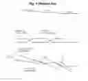
A downshifting process of a DCT when a vehicle provided with the DCT decelerates, for example, to stop, will be described below with reference to FIG. 1.
FIG. 1 illustrates a process of downshifting from the preceding gear N+1 to a subsequent gear N−1 via a current gear N when decelerating a DCT vehicle including a first input shaft and a second input shaft which are respectively coupled to a first clutch and a second clutch. When in the current gear N, the first clutch which has been in an engaged state in the preceding gear N+1 is released, and the second clutch engages to allow transmission of torque. Thereafter, contrary to this, when in the subsequent gear N−1, the first clutch enters the engaged state to allow transmission of torque, and the second clutch is released.
To shift from the current gear N to the subsequent gear N−1, synchronization of a synchronizer takes place to engage a shift gear of the subsequent gear N−1, following engaging the first clutch and releasing the second clutch so that power is transmitted through the shift gear of the subsequent gear N−1.
However, during the synchronization conducted to engage a shift gear of the subsequent gear N−1, shift shock may occur. In detail, if the rpm of the first input shaft is less than that of the output shaft when engaging the shift gear of the subsequent gear N−1, backlash of elements pertaining to transmission of power between the input shaft and the output shaft, which has been arranged in one direction when synchronization takes place to engage the shift gear of the subsequent gear N−1, is rearranged in the reverse direction when the synchronization is completed or the transmission of power from the input shaft to the output shaft begins. At this time, shift shock and noise occur.
In other words, during synchronization for engagement of the shift gear of the subsequent gear N−1, if the rpm of the first input shaft coupled to the first clutch is less than that of the output shaft, when synchronization begins to take place as the sleeve moves, torque is applied from the output shaft in a direction in which the first input shaft is operated. At this time, backlash of elements, for example, a hub, the sleeve, shift gears, etc., which pertain to a power transmission path from the output shaft to the first input shaft is arranged in one direction.
Subsequently, when the sleeve further moves, the sleeve passes over a synchronizer ring and a key. Thereby, the compression force with which the sleeve pushed the synchronizer ring is removed, resulting in a momentary breakdown of the synchronization.
During breakdown of the synchronization, if there is no frictional resistance induced as a result of the rotation of the first input shaft, the first input shaft may rotate freely and thus maintains the rpm when in the synchronized state. The rpm of the output shaft reduces because the vehicle is decelerating. As a result, just before the sleeve which has further moved engages with the clutch gear, the rpm of the first input shaft exceeds that of the output shaft.
In this state, if the sleeve just moves and engages with the clutch gear, torque is applied to the elements in the direction in which the first input shaft that is faster than the output shaft rotates the output shaft. Thus, the backlash of the elements that have been arranged in one direction when the synchronization begins are rearranged in the reverse direction. Because of such a phenomenon, the corresponding elements between the first input shaft and the output shaft that have been rotating at high speeds collide with each other, thus causing shock and noise.
Such shift shock and noise which are induced during the above-mentioned process of the conventional technique deteriorate the quietness of the vehicle, causes a user discomfort, and reduce the marketability of the vehicle.
For reference, the circle portion A of FIG. 1 means shock and noise which occur from the first input shaft when shifting from the current gear N to the subsequent gear N−1, and the circle portion B indicates the shock and noise which are caused by the second input shaft when shifting from the subsequent gear N−1 to a lower subsequent gear.
The information disclosed in this Background of the Invention section is only for enhancement of understanding of the general background of the invention and should not be taken as an acknowledgement or any form of suggestion that this information forms the prior art already known to a person skilled in the art.
BRIEF SUMMARY
Various aspects of the present invention are directed to providing a method of controlling a DCT of a vehicle in such a way that, when shifting gears from the current gear to a lower gear in response to deceleration of the vehicle, shift shock and noise are prevented from being induced by the backlash occurring between elements between an input shaft and an output shaft, thus enhancing the gear shift quality, thereby improving the quietness and riding comfort of the vehicle, and enhancing the marketability of the vehicle.
A method of controlling a DCT (double clutch transmission) of a vehicle to conduct a series of downshifting operations from a preceding gear to a subsequent gear via a current gear in response to deceleration of the vehicle may include slip-controlling, continuously, a clutch which may have been in an engaged state in the preceding gear, at least until a shift gear of the subsequent gear may be engaged.
The slip-controlling may include maintaining the engaged state of the clutch with the current gear.
The slip-controlling may include slip-controlling the clutch to control an amount of torque transmitted by the clutch in response to a deceleration rate of the vehicle.
The slip-controlling may include slip-controlling the clutch such that the amount of torque transmitted by the clutch may be increased as the deceleration rate of the vehicle increases.
The slip-controlling may include continuously slip-controlling the clutch, which may have been in the engaged state in the preceding gear, all throughout the current gear to the subsequent gear.
The methods and apparatuses of the present invention have other features and advantages which will be apparent from or are set forth in more detail in the accompanying drawings, which are incorporated herein, and the following Detailed Description, which together serve to explain certain principles of the present invention.
BRIEF DESCRIPTION OF THE DRAWINGS
FIG. 1 is a graph illustrating a method of controlling a DCT of a vehicle, according to a conventional technique.
FIG. 2 is a flowchart of a method of controlling a DCT of a vehicle, according to an exemplary embodiment of the present invention.
FIG. 3 is a graph illustrating the method of controlling the DCT according to an exemplary embodiment of the present invention.
It should be understood that the appended drawings are not necessarily to scale, presenting a somewhat simplified representation of various features illustrative of the basic principles of the invention. The specific design features of the present invention as disclosed herein, including, for example, specific dimensions, orientations, locations, and shapes will be determined in part by the particular intended application and use environment.
In the figures, reference numbers refer to the same or equivalent parts of the present invention throughout the several figures of the drawing.
DETAILED DESCRIPTION
Reference will now be made in detail to various embodiments of the present invention(s), examples of which are illustrated in the accompanying drawings and described below. While the invention(s) will be described in conjunction with exemplary embodiments, it will be understood that the present description is not intended to limit the invention(s) to those exemplary embodiments. On the contrary, the invention(s) is/are intended to cover not only the exemplary embodiments, but also various alternatives, modifications, equivalents and other embodiments, which may be included within the spirit and scope of the invention as defined by the appended claims.
Hereinafter, an embodiment of the present invention will be described in detail with reference to the attached drawings.
Referring to FIGS. 2 and 3, the present invention provides a method of controlling a DCT of a vehicle according to an exemplary embodiment of the present invention when a series of downshifting operations from a preceding gear N+1 to a subsequent gear N−1 via a current gear N is conducted in response to deceleration of the vehicle. The method of the present invention includes a slip control step S10 of continuously slip-controlling a clutch, which has been in an engaged state in the preceding gear N+1, at least until a shift gear of the subsequent gear N−1 is engaged.
In detail, when shifting to the subsequent gear N−1, the clutch (the first clutch) which has been in the engaged state in the preceding gear N+1 is slip-controlled, rather than being completely released in the current gear N. Thus, gears are shifted to the subsequent gear N−1 while an rpm of a corresponding input shaft coupled to the clutch is maintained higher than that of an output shaft by fine torque transmitted by the clutch. Therefore, the present invention can prevent shift shock and noise which have occurred due to the conversion of backlash arrangement in the reverse direction in the conventional technique.
At the slip control step S10, the amount of torque transmitted by the clutch is controlled by slip-controlling the clutch in response to deceleration of the vehicle. For example, as a deceleration rate of the vehicle increases, the amount of torque transmitted by the clutch is increased or reduced by slip-controlling the clutch so that variation of backlash arrangement is minimized and a damping effect is increased.
As shown in FIG. 3, at the slip control step S10, the clutch (the first clutch) which has been in the engaged state in the preceding gear N+1 is slip-controlled until after the shift gear of the subsequent gear N−1 is engaged. The slip control is conducted continuously throughout the current gear N to the subsequent gear N−1.
As such, when in the current gear N, if the clutch (the first clutch) which has been in the engaged state in the preceding gear N+1 and will enter the engaged state in the subsequent gear N−1 to transmit power is slip-controlled, the rpm of the input shaft (the first input shaft) coupled to the clutch is at least equal to or higher than the rpm of the output shaft which is decelerating. Thus, torque is applied in the direction in which the input shaft operates the output shaft while synchronization conducted to engage the shift gear of the subsequent gar N−1 takes place to shift to the subsequent gear N−1. Thereafter, even when a sleeve completely engages with the shift gear of the subsequent gear N−1 after passing through a synchronization breakdown section, the rpm of the input shaft is higher than that of the output which is decelerating, and torque is still applied in the direction in which the input shaft operates the output shaft. Hence, backlash arrangement of elements between the input shaft and the output shaft which pertain to the power transmission can stay in a stable state without direction conversion during the shifting operation, thus preventing shift shock or noise from occurring.
Of course, the above-described shifting operation is conducted in the same manner even when shifting from the subsequent gear N−1 to a lower subsequent gear.
As described above, in a method of controlling a DCT of a vehicle according to an exemplary embodiment of the present invention, when shifting gears from the current gear to a lower target gear in response to deceleration of the vehicle, shift shock and noise can be prevented from being induced by backlash occurring between elements between an input shaft and an output shaft. Therefore, the gear shift quality is enhanced, thus improving the quietness and riding comfort of the vehicle, and enhancing the marketability of the vehicle.
The foregoing descriptions of specific exemplary embodiments of the present invention have been presented for purposes of illustration and description. They are not intended to be exhaustive or to limit the invention to the precise forms disclosed, and obviously many modifications and variations are possible in light of the above teachings. The exemplary embodiments were chosen and described in order to explain certain principles of the invention and their practical application, to thereby enable others skilled in the art to make and utilize various exemplary embodiments of the present invention, as well as various alternatives and modifications thereof. It is intended that the scope of the invention be defined by the Claims appended hereto and their equivalents.
Claims
What is claimed is:1. A method of controlling a DCT (double clutch transmission) of a vehicle to conduct a series of downshifting operations from a preceding gear to a subsequent gear via a current gear in response to deceleration of the vehicle, the method comprising:
slip-controlling, continuously, a clutch which has been in an engaged state in the preceding gear, at least until a shift gear of the subsequent gear is engaged.
2. The method as set forth in claim 1, wherein the slip-controlling includes maintaining the engaged state of the clutch with the current gear.
3. The method as set forth in claim 1, wherein the slip-controlling includes slip-controlling the clutch to control an amount of torque transmitted by the clutch in response to a deceleration rate of the vehicle.
4. The method as set forth in claim 3, wherein the slip-controlling includes slip-controlling the clutch such that the amount of torque transmitted by the clutch is increased as the deceleration rate of the vehicle increases.
5. The method as set forth in claim 1, wherein the slip-controlling includes continuously slip-controlling the clutch, which has been in the engaged state in the preceding gear, all throughout the current gear to the subsequent gear.
6. A method of controlling a DCT (double clutch transmission) of a vehicle to conduct a series of downshifting operations from a preceding gear to a subsequent gear via a current gear in response to deceleration of the vehicle, the method comprising:
maintaining an engaged state of a clutch, which has been in the engaged state in the preceding gear, without being completely released with the current gear at least until the subsequent gear is engaged so that gears are shifted to the subsequent gear while an rpm of a corresponding input shaft coupled to the clutch is maintained equal to or higher than an rpm of an output shaft by fine torque transmitted by the clutch.
Images & Drawings included:



Sources:
- United States Patent and Trademark Office - verify current appl. status at the USPTO↗
Similar patent applications:
- » 20120312109
Method of controlling double clutch transmission of vehicle - » 20140001002
Method of controlling a double clutch in a vehicle transmission, and clutch control system for controlling a double clutch - » 20150300487
Method of controlling a double clutch in a vehicle transmission, and clutch control system for controlling a double clutch - » 20100113219
Method for controlling the upshift operation in a motor vehicle equipped with a double clutch transmission
Recent applications in this class:
- » 20240391448 2024-11-28
Method and device for determining a torque, and agricultural towing vehicle - » 20240367635 2024-11-07
Clutch control device - » 20240336248 2024-10-10
VEHICLE DRIVE TRAIN OF A VEHICLE - » 20240317203 2024-09-26
METHOD AND CONTROL ARRANGEMENT FOR CHANGING AN ACTIVATION STATE FOR A POWER TAKE-OFF - » 20240300469 2024-09-12
Vehicle driving apparatus - » 20240253610 2024-08-01
Active torque management clutch system - » 20230071508 2023-03-09
Method for turning off an internal combustion engine of a vehicle powertrain system and a vehicle powertrain system - » 20230038261 2023-02-09
Control apparatus for vehicle - » 20220274581 2022-09-01
Control device and control method for vehicle, and non-transitory computer readable medium - » 20220126809 2022-04-28
Control device for vehicular transfer
Recent applications for this Assignee:
- » 20250293967 2025-09-18
VEHICLE CONTROL APPARATUS AND METHOD THEREOF - » 20250293557 2025-09-18
MOTOR WITH A COOLING STRUCTURE - » 20250293373 2025-09-18
BATTERY ASSEMBLY - » 20250293361 2025-09-18
FUEL CELL POWER GENERATION MODULE - » 20250293308 2025-09-18
ELECTRODE ASSEMBLY AND ALL-SOLID STATE BATTERY INCLUDING THE SAME - » 20250292638 2025-09-18
SYSTEM AND METHOD FOR MONITORING POWER OF A VEHICLE - » 20250292590 2025-09-18
METHOD AND APPARATUS FOR CONTEXT-RECOGNITION OBJECT ACTION PREDICTION AND PATH PLANNING FOR AUTONOMOUS VEHICLES BASED ON PEDESTRIAN MOTION PREDICTION - » 20250290600 2025-09-18
PRESSURE VESSEL - » 20250289441 2025-09-18
METHOD AND APPARATUS FOR CALIBRATING ORIENTATION ANGLE OF VEHICLE SENSOR - » 20250289422 2025-09-18
SYSTEM AND METHOD FOR GENERATING EMERGENCY COLLISION AVOIDANCE STRATEGY FOR A VEHICLE