Compartmented Tray for Condiment Containers
US20120318705A1
2012-12-20
13/163,333
2011-06-17
Abstract:
A compartmented tray has an array of receptacle interconnected by a common top wall. The top wall has a peripheral flange which reinforces the tray, and the receptacles are all interconnected by troughs which further increase the tray's flexural stiffness.
Assignee:
- CLASSIC SIGNATURE FOODS, INC. 1 🇺🇸 Peachtree City, GA, United States
Interested in similar patents?
Get notified when new applications in this technology area are published.
Classification:
B65D1/243 » CPC main
Containers having bodies formed in one piece, e.g. by casting metallic material, by moulding plastics, by blowing vitreous material, by throwing ceramic material, by moulding pulped fibrous material, by deep-drawing operations performed on sheet material; Boxes or like containers with side walls of substantial depth for enclosing contents with moulded compartments or partitions Crates for bottles or like containers
B65D2501/24019 » CPC further
Containers having bodies formed in one piece; Boxes or like containers with moulded compartments or partitions; Details relating to bottle crates; Materials Mainly plastics
B65D2501/24108 » CPC further
Containers having bodies formed in one piece; Boxes or like containers with moulded compartments or partitions; Details relating to bottle crates; Construction of the walls; Height of the side walls corresponding to part of the height of the bottles
B65D2501/24254 » CPC further
Containers having bodies formed in one piece; Boxes or like containers with moulded compartments or partitions; Details relating to bottle crates; Arrangements for locating the bottles; Construction of locating arrangements; Pillars of star-like cross-section
B65D2501/2435 » CPC further
Containers having bodies formed in one piece; Boxes or like containers with moulded compartments or partitions; Details relating to bottle crates; Arrangements for locating the bottles; Position pattern Columns and rows
B65D2501/24764 » CPC further
Containers having bodies formed in one piece; Boxes or like containers with moulded compartments or partitions; Details relating to bottle crates Reinforcements
B65D2501/24834 » CPC further
Containers having bodies formed in one piece; Boxes or like containers with moulded compartments or partitions; Details relating to bottle crates; Reinforcements; Location of the reinforcing means Inside the crate
B65D85/72 IPC
Containers, packaging elements or packages, specially adapted for particular articles or materials for materials not otherwise provided for for edible or potable liquids, semiliquids, or plastic or pasty materials
B65D1/36 IPC
Containers having bodies formed in one piece, e.g. by casting metallic material, by moulding plastics, by blowing vitreous material, by throwing ceramic material, by moulding pulped fibrous material, by deep-drawing operations performed on sheet material; Trays or like shallow containers with moulded compartments or partitions
Description
BACKGROUND OF THE INVENTION
This invention relates to a compartmented tray for portion control cups for holding condiments such as salad dressing.
Prior inventors have proposed numerous compartmented trays for various products. For restaurant use, a tray for holding a number of cups containing condiments should be disposable and inexpensive to make, yet strong. In particular, the tray should be designed so that, when fully loaded, it can be grasped and lifted at only one end without bending substantially, buckling or breaking In addition, the tray should be nestable and should achieve high packing density.
SUMMARY OF THE INVENTION
An object of the invention is provide a molded plastic tray for holding containers, for example portion control cups of salad dressing.
These and other objects are attained by a compartmented tray as described below.
In the description and claims below, several dimensions are given in proportion to one another, as the invention may be scaled up or down considerably for different intended applications. Describing the structure by its proportions best defines the invention, whatever its overall size.
BRIEF DESCRIPTION OF THE DRAWINGS
In the accompanying drawings,
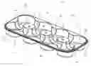
FIG. 1 is a perspective view of a compartmented tray embodying the invention, shown from the front, end and top;
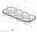
FIG. 2 is a bottom plan view thereof;
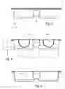
FIG. 3 is an end view thereof;
FIG. 4 is a sectional view taken on the line 4-4 in FIG. 2; and
FIG. 5 is a sectional view taken on the line 5-5 in FIG. 2.
DESCRIPTION OF THE PREFERRED EMBODIMENT
A compartmented tray 10 embodying the invention is molded from a polymeric plastic material.
The material presently preferred is polyethylene terephthalate (PET), because it is acceptable for food use, and is inexpensive, strong, stiff, attractive, and is a thermoplastic which can be molded in conventional injection molding machines.
Other materials might be used to make the tray, however.
The tray material is preferably of substantially uniform thickness. The thickness of the material is chosen to provide adequate strength for a particular intended use, considering that the tray must have sufficient flexural strength such that, when fully loaded, it is lifted at opposite ends, or by only one end, it does not buckle or deform substantially. Suitable thicknesses will usually be within the range of 0.020 to 0.030 inches.
As one can see in FIG. 1, the preferred tray 10 has at least two rows of receptacles 12, a two-by-four receptacle array being shown. Preferably, the receptacles are identical in size, shape and spacing. Each receptacle has a bottom wall 14 with a circular periphery and a side wall 16 extending upward from the periphery of the bottom wall around a vertical receptacle axis “V”. The side walls have a taper angle a in the range of 1° to 10°. The center-to-center distance of the receptacles is identified by dimension “C”.
The receptacles are interconnected by a planar top wall 18 which extends outward from said side walls and is bounded by a continuous peripheral rim 20. The overall height of the tray, and thus the depth of the receptacles, is identified by dimension “H” (FIG. 4).
All the receptacles are interconnected by troughs 22, 24. Each trough has a rounded bottom 26 (preferably semicylindrical) extending along a horizontal axis “T” and planar side walls 28 which diverge slightly at an angle in the range of 1° to 3°. Preferably, the trough axis intersects the vertical axis “V” of each receptacle through which the trough passes.
The horizontal axis of each trough lies a distance h1 (see FIG. 4) below the top wall. That distance may be in the range of 0.1 to 0.5 times the tray height, i.e., 0.1≦h1/H≦0.5. The bottoms of the troughs lie above the bottoms of the receptacles, preferably a distance h2 in the range of 0.1 to 0.5 time the tray height, i.e., 0.1≦h2/H≦0.5. Even at the lower limit, the bottoms of the troughs are well above the bottoms of the receptacles.
Each receptacle bottom has an inside diameter D and the semicylindrical portion of each trough has an inside diameter d. The preferred ratio d/D is in the range of 0.4 to 0.6.
The dimensions and proportions for a presently most preferred tray are shown in the table below:
| rows of receptacles | 2 | |
| receptacles per row | 4 | |
| tray height H | 1.00 inch | |
| receptacle diameter D | 1.80 inch | |
| trough diameter d | 0.50 inch | |
| receptacle spacing C | 2.35 inch | |
| receptacle taper α | 6° | |
| trough axis to top h1 | .25 inch | |
| trough to bottom h2 | .25 inch | |
| h1/H | .25 | |
| h2/H | .25 | |
Referring again to FIG. 1, one can see that the troughs and peripheral receptacle walls define octagonal mesas 30 between each pair of diagonally adjacent receptacles. The mesa tops are preferably coplanar with the top wall.
The rim of the tray, best seen in FIG. 3, has an L-shaped reinforcing flange 32 that extends downward and then outward from the top wall. The rim gives the tray much greater flexural stiffness than it would otherwise have, and in conjunction with the stiffening provided by the troughs, results in a tray which is flexurally stiff and strong and can be lifted by one or both ends when fully loaded without failing.
Since the invention is subject to modifications and variations, it is intended that the foregoing description and the accompanying drawings shall be interpreted as only illustrative of the invention defined by the following claims.
Claims
I claim:1. A tray for holding condiment containers, said tray comprising
at least two rows of receptacles, each receptacle having a bottom wall with a circular periphery and a side wall extending upward from the periphery of the bottom wall around a vertical receptacle axis,
said receptacles being interconnected by a planar top wall which extends outward from said side walls to a continuous peripheral rim,
all said receptacles also being interconnected by troughs, each said trough having a rounded bottom extending along a horizontal axis which intersects the vertical axis of each receptacle through which the trough passes.
2. The tray of claim 1, wherein said side walls are tapered at and an angle of from 1° to 10°.
3. The tray of claim 1, wherein said recesses are substantially identical in size, shape and spacing.
4. The tray of claim 1, wherein the tray is formed of a polymeric material.
5. The tray of claim 1, wherein the polymeric material is of substantially uniform thickness.
6. The tray of claim 1, wherein said thickness is in the range of 0.020 to 0.040 inch.
7. The tray of claim 1, wherein the polymeric material is polyethylene terephthalate.
8. The tray of claim 1, wherein the horizontal axis of each trough lies a distance hl below the top wall.
9. The tray of claim 1, wherein the distance hl divided by the tray height H is in the range of 0.1 to 0.5.
10. The tray of claim 1, wherein each receptacle bottom has an inside diameter D and each said trough bottom has an inside diameter d, and the ratio d/D is in the range of 0.4 to 0.6.
11. The tray of claim 1, wherein said trough bottoms lie a distance h2 above said bottom walls.
12. The tray of claim 1, wherein said distance h2 is in the range of 0.1 to 0.5.
13. The tray of claim 1, wherein the troughs and peripheral receptacle walls define octagonal mesas between each pair of diagonally adjacent receptacles.
14. The tray of claim 1, wherein the mesas are coplanar with the top wall.
15. The tray of claim 1, wherein the rim comprises a reinforcing flange extending downward from the top wall.
Images & Drawings included:

Sources:
- United States Patent and Trademark Office - verify current appl. status at the USPTO↗
Recent applications in this class:
- » 20240262561 2024-08-08
PROTECTOR DEVICE FOR CONTAINERS - » 20230271742 2023-08-31
THERMAL REGULATING LAY FLAT BEVERAGE CONTAINER PACKAGING - » 20230227198 2023-07-20
REUSABLE RECYCLABLE THERMOFORMED SHIPPING CONTAINERS - » 20230159211 2023-05-25
RECONFIGURABLE BEVERAGE CRATE - » 20220402644 2022-12-22
USE OF A POLYMER COMPOSITION, CRATE MANUFACTURED IN SUCH POLYMER COMPOSITION AND METHOD OF MANUFACTURING SUCH CRATE OR PALLET - » 20220402643 2022-12-22
LOW DEPTH CRATE - » 20220355966 2022-11-10
Low depth crate for containers - » 20220250783 2022-08-11
Nestable bottle crate - » 20220219858 2022-07-14
Crate divider system - » 20210354870 2021-11-18
Thermal regulating lay flat beverage container packaging