PERMANENT MAGNET ROTOR
US20130038161A1
2013-02-14
13/292,054
2011-11-08
Abstract:
A permanent magnet rotor for a motor, the permanent magnet rotor including an iron core and a permanent magnet. The iron core includes an annular ring having a central axial bore and a plurality of magnetic induction blocks protruding outwards from an outer side of the annular ring. Between two adjacent magnetic induction blocks form a radial recess for mounting the permanent magnets. The magnetic induction blocks at both sides of an opening of the radial recess protrude with a hook block. The section of an outer side surface of the magnetic induction blocks is a circular-arc line and the outer side surface employs a point with a distance deviating from the center of the central axial bore as a center of circle. The permanent magnet rotor has a simple structure, low magnetic leakage and torque ripple, big counter-electromotive force constant, and smooth waveform of counter-electromotive force.
Assignee:
- Zhongshan Broad-Ocean Motor Manufacturing Co., Ltd. 52 🇨🇳 Zhongshan, China
Interested in similar patents?
Get notified when new applications in this technology area are published.
Classification:
H02K2213/03 » CPC further
Specific aspects, not otherwise provided for and not covered by codes - Machines characterised by numerical values, ranges, mathematical expressions or similar information
H02K1/27 IPC
Details of the magnetic circuit characterised by the shape, form or construction; Rotating parts of the magnetic circuit Rotor cores with permanent magnets
Description
CROSS-REFERENCE TO RELATED APPLICATIONS
Pursuant to 35 U.S.C. § 119 and the Paris Convention Treaty, this application claims the benefit of Chinese Patent Application No. 201120290991.3, filed Aug. 11, 2011, the contents of which are incorporated herein by reference.
BACKGROUND OF THE INVENTION
1. Field of the Invention
The invention relates to a permanent magnet rotor of a motor.
2. Description of the Related Art
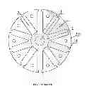
As shown in FIG. 1, a conventional permanent magnet rotor of a motor includes an annular ring 2 having a central axial bore 1 and a plurality of magnetic induction blocks 3 protruding outwards from an outer side of the annular ring 2. Between two adjacent magnetic induction blocks 3 form a recess 4 for mounting the permanent magnets 3. The magnetic induction blocks 3 at both sides of an opening of the recess 4 protrude with a hook block 31. An outer contour of the magnetic induction blocks 3 is formed by a circular-arc line 33 and the circular-arc line 33 employs the center of the central axial bore 1 as a center of circle. Such structure has the disadvantage of large magnetic leakage of the rotor core, high torque ripple, and distorted top waveform of counter-electromotive force.
SUMMARY OF THE INVENTION
In view of the above-described problems, it is one objective of the invention to provide a permanent magnet rotor of a motor that has a simple structure, low magnetic leakage and torque ripple, big counter-electromotive force constant, smooth waveform of counter-electromotive force, high service performance, and low loss.
To achieve the above objective, in accordance with one embodiment of the invention, there provided is a permanent magnet rotor of a motor comprising an iron core and a permanent magnet, wherein the iron core comprises an annular ring having a central axial bore and a plurality of magnetic induction blocks protruding outwards from an outer side of the annular ring; between two adjacent magnetic induction blocks form a radial recess for mounting the permanent magnets; the magnetic induction blocks at both sides of an opening of the radial recess protrude with a hook block; the section of an outer side surface of the magnetic induction blocks is an circular-arc line and the outer side surface employs a point with a distance deviating from the center of the central axial bore as a center of circle.
In a class of this embodiment, the distance deviating from the center of the central axial bore is 5-20 mm.
In a class of this embodiment, the maximum external diameter of the iron core is 80-90 mm and the number of the magnetic induction blocks is 10.
In a class of this embodiment, a distance between the two hook blocks arranged at the opening of the same radial recess is 3.5-5 mm.
In a class of this embodiment, a convex plate is arranged at the middle bottom of the radial recess.
In a class of this embodiment, each magnetic induction block is arranged with a through hole to facilitate mounting.
In a class of this embodiment, a line connecting the center of the central axial bore and the center of circle is a central boundary line of the circular-arc line of the outer side surface.
Advantages of the invention are summarized below:
-
- 1) the iron core comprises an annular ring having a central axial bore and a plurality of magnetic induction blocks protruding outwards from outer side of the annular ring, between two adjacent magnetic induction blocks form a radial recess for mounting the permanent magnets, the magnetic induction blocks at both sides of the opening of the radial recess protrude with a hook block, the section of the outer side surface of the magnetic induction blocks is an circular-arc line and the outer side employs a point with a distance deviating from the center of the central axial bore as the center of circle. Such structure is helpful to reduce magnetic leakage of the rotor core, lower cogging torque ripple, and achieve a big counter-electromotive force constant and smooth waveform of the counter-electromotive force. Therefore, the motor's performance has been improved and losses have been reduced;
- 2) the distance deviating from the center of the central axial bore is 5-20 mm, the maximum external diameter of the iron core is 80-90 mm and the number of the magnetic induction blocks is 10. It further helps to reduce the magnetic leakage of the rotor core due to the optimized dimension parameters; and
- 3) the distance between the two hook blocks arranged at the opening of the same radial recess is 3.5-5 mm and a convex plate is arranged at the middle bottom of the radial recess, thus it can further reduce magnetic leakage of the rotor core.
BRIEF DESCRIPTION OF THE DRAWINGS
FIG. 1 is a schematic diagram of a permanent magnet rotor in the prior art;
FIG. 2 is a schematic diagram of a permanent magnet rotor according to one embodiment of the invention;
FIG. 3 is a schematic diagram of a iron core according to one embodiment of the invention; and
FIG. 4 is a design principle diagram of a permanent magnet rotor according to one embodiment of the invention.
DETAILED DESCRIPTION OF THE EMBODIMENTS
The invention is explained in further detail below with reference to the accompanying drawings and embodiments.
As shown in FIGS. 2, 3, and 4, a permanent magnet rotor of a motor comprises an iron core and a permanent magnet 5. The iron core comprises an annular ring 2 having a central axial bore 1 and a plurality of magnetic induction blocks 3 protruding outwards from an outer side of the annular ring 2. Between two adjacent magnetic induction blocks 3 form a radial recess 4 for mounting a permanent magnet 6. The magnetic induction blocks 3 at both sides of an opening 41 of the radial recess 4 protrude with a hook block 32. The section of the outer side surface 31 of the magnetic induction blocks 3 is an circular-arc line and the outer side surface 31 employs a point A with a distance H deviating from the center O of the central axial bore 1 as a center of circle. The distance H deviating from the center O of the central axial bore 1 is 5-20 mm The maximum external diameter D of the iron core is 80-90 mm and the number of the magnetic induction blocks is 10, a distance L between the two hook blocks 32 arranged at the opening 41 of the same radial recess 4 is 3.5-5 mm. A convex plate 42 is arranged at the middle bottom of the radial recess 4. A line connecting the center O of the central axial bore 1 and the center of circle A is a central boundary line of the circular-arc line of the outer side surface 31.
In accordance with the invention, the section of the outer side surface 31 of the magnetic induction blocks 3 is an circular-arc line and the outer side surface 31 employs a point A with a distance H deviating from the center O of the central axial bore 1 as the center of circle. The distance H deviating from the center O of the central axial bore 1 is 5-20 mm. Such structure changes the shape of the outer side surface 31 of the magnetic induction blocks 3, thus it has a simple structure, low magnetic leakage and torque ripple, big counter-electromotive force constant, and smooth waveform of counter-electromotive force. Thus, the motor's performance has been improved and losses have been reduced. The permanent magnet rotor of the invention is mainly used for air-conditioned motors.
While particular embodiments of the invention have been shown and described, it will be obvious to those skilled in the art that changes and modifications may be made without departing from the invention in its broader aspects, and therefore, the aim in the appended claims is to cover all such changes and modifications as fall within the true spirit and scope of the invention.
Claims
The invention claimed is:1. A permanent magnet rotor of a motor, comprising an iron core and a permanent magnet, wherein
the iron core comprises an annular ring having a central axial bore and a plurality of magnetic induction blocks protruding outwards from an outer side of the annular ring;
between two adjacent magnetic induction blocks form a radial recess for mounting the permanent magnets;
the magnetic induction blocks at both sides of an opening of the radial recess protrude with a hook block; and
the section of an outer side surface of the magnetic induction blocks is an circular-arc line and the outer side surface employs a point with a distance deviating from the center of the central axial bore as a center of circle.
2. The permanent magnet rotor of claim 1, wherein the distance deviating from the center of the central axial bore is 5-20 mm.
3. The permanent magnet rotor of claim 1, wherein the maximum external diameter of the iron core is 80-90 mm and the number of the magnetic induction blocks is 10.
4. The permanent magnet rotor of claim 1, wherein a distance between two hook blocks arranged at the opening of the same radial recess is 3.5-5 mm.
5. The permanent magnet rotor of claim 2, wherein a distance between two hook blocks arranged at the opening of the same radial recess is 3.5-5 mm.
6. The permanent magnet rotor of claim 3, wherein a distance between two hook blocks arranged at the opening of the same radial recess is 3.5-5 mm.
7. The permanent magnet rotor of claim 4, wherein a convex plate is arranged at the middle bottom of the radial recess.
8. The permanent magnet rotor of claim 5, wherein a convex plate is arranged at the middle bottom of the radial recess.
9. The permanent magnet rotor of claim 6, wherein a convex plate is arranged at the middle bottom of the radial recess.
10. The permanent magnet rotor of claim 7, wherein each magnetic induction block is arranged with a through hole.
11. The permanent magnet rotor of claim 8, wherein each magnetic induction block is arranged with a through hole.
12. The permanent magnet rotor of claim 9, wherein each magnetic induction block is arranged with a through hole.
13. The permanent magnet rotor of claim 1, wherein a line connecting the center of the central axial bore and the center of circle is a central boundary line of the circular-arc line of the outer side surface.
Images & Drawings included:


Sources:
- United States Patent and Trademark Office - verify current appl. status at the USPTO↗
Similar patent applications:
- » 20180269732
Interior permanent magnet type rotor, permanent magnet type motor having the interior permanent magnet type rotor, and compressor having the permanent magnet type motor - » 20100277025
Table for permanent magnet rotor and method for manufacturing permanent magnet rotor - » 20120233848
Table for permanent magnet rotor and method for manufacturing permanent magnet rotor - » 20240413682
DOUBLE-LAYER INTERIOR PERMANENT-MAGNET ROTOR, DOUBLE-LAYER INTERIOR PERMANENT-MAGNET ROTARY ELECTRIC MACHINE, AND METHOD FOR MANUFACTURING DOUBLE-LAYER INTERIOR PERMANENT-MAGNET ROTOR - » 20080088194
Permanent-Magnet Rotor And A Method For Manufacturing A Permanent-Magnet Rotor - » 20170070129
METHOD FOR MANUFACTURING AN INTERIOR PERMANENT MAGNET ROTOR UNIT AND APPARATUS FOR MANUFACTURING AN INTERIOR PERMANENT MAGNET ROTOR - » 20150048620
Permanent magnet rotor with permanent magnet modules arranged on the rotor - » 20170098969
PERMANENT MAGNET ROTOR AND PERMANENT MAGNET ROTATING ELECTRICAL MACHINE - » 20170302117
PERMANENT MAGNET ROTOR AND PERMANENT MAGNET SYNCHRONOUS ROTATING ELECTRICAL MACHINE - » 20180123436
Permanent magnet rotor and permanent magnet rotary assembly
Recent applications in this class:
- » 20250149940 2025-05-08
FLUX-CONCENTRATED MOTOR - » 20250141288 2025-05-01
ROTATING ELECTRIC MACHINE - » 20250105687 2025-03-27
DYNAMOELECTRIC ROTARY MACHINE - » 20250055334 2025-02-13
HIGH PERFORMANCE ELECTROMAGNETIC MACHINE AND COOLING SYSTEM - » 20240364156 2024-10-31
ROTOR AND MOTOR - » 20240356398 2024-10-24
ROTOR, MOTOR USING THE ROTOR, AND ELECTRONIC DEVICE - » 20240275225 2024-08-15
ROTOR, MOTOR USING THE ROTOR AND ELECTRONIC DEVICE - » 20240275224 2024-08-15
FLUX CONCENTRATE TYPE ROTOR HAVING ARC TYPE PERMANENT MAGNETS - » 20240266894 2024-08-08
FLUX CONCENTRATE TYPE MOTOR - » 20240146128 2024-05-02
ELECTRIC MOTOR, KITCHEN MACHINE AND MANUFACTURING METHOD
Recent applications for this Assignee:
- » 20170085140 2017-03-23
Plastic-packaged stator and external rotor motor comprising the same - » 20170074273 2017-03-16
Blower comprising a pressure measuring connector - » 20160254712 2016-09-01
Rotor with embedded permanent magnets, assembly structure and motor comprising the same - » 20150372555 2015-12-24
Wire terminal joint of motor stator winding - » 20150372549 2015-12-24
Motor - » 20150229171 2015-08-13
Permanent magnet rotor - » 20150162860 2015-06-11
Method for controlling three-phase brushless DC motor comprising single hall sensor - » 20150162792 2015-06-11
Permanent magnet rotor - » 20150091482 2015-04-02
Variable speed fan motor - » 20140183983 2014-07-03
Plastic-package motor