Method for controlling the locomotion of a motor vehicle
US20130041562A1
2013-02-14
13/642,244
2011-03-02
✅ Patent granted
US 9,181,885 B2
2015-11-10
WO; PCT/EP2011/053113; 20110302
WO; WO2011/131406; 20111027
Tuan C. To | Isaac Smith
Davis & Bujold, P.L.L.C. | Michael J. Bujold
2031-12-25
Abstract:
A method for drive control of a motor vehicle in a drive train which comprises a drive engine built as a turbo-charged internal combustion engine, a startup and shifting clutch built as an automated friction clutch, and a transmission built as an automatic stepped transmission. The method overcomes drive engine torque deficiencies while traveling in which such torque deficiencies occur when the driver demands power corresponding to a target torque of the drive engine which is above the spontaneously attainable maximum torque. To avoid downshifting or starting from standstill, initially the clutch is disengaged up to slipping operation, the drive engine is then accelerated to the boost threshold speed or an engine speed which is slightly above the boost threshold speed, and the drive engine is then loaded up to substantially the full load torque with a substantially constant engine speed before the slipping operation of the clutch ends.
Assignee:
- ZF FRIEDRICHSHAFEN AG 3,767 🇩🇪 Friedrichshafen, Germany
Applicant:
Interested in similar patents?
Get notified when new applications in this technology area are published.
Classification:
Y02T10/12 » CPC further
Road transport of goods or passengers; Internal combustion engine [ICE] based vehicles Improving ICE efficiencies
Y02T10/12 » CPC further
Road transport of goods or passengers; Internal combustion engine [ICE] based vehicles Improving ICE efficiencies
B60W10/11 IPC
Conjoint control of vehicle sub-units of different type or different function including control of change-speed gearings Stepped gearings
F02D41/0007 » CPC main
Electrical control of supply of combustible mixture or its constituents; Controlling intake air for control of turbo-charged or super-charged engines
B60W10/06 » CPC further
Conjoint control of vehicle sub-units of different type or different function including control of propulsion units including control of combustion engines
B60W30/1882 » CPC further
Purposes of road vehicle drive control systems not related to the control of a particular sub-unit, e.g. of systems using conjoint control of vehicle sub-units, or advanced driver assistance systems for ensuring comfort, stability and safety or drive control systems for propelling or retarding the vehicle; Propelling the vehicle; Controlling power parameters of the driveline, e.g. determining the required power characterised by the working point of the engine, e.g. by using engine output chart
B60W50/06 » CPC further
Details of control systems for road vehicle drive control not related to the control of a particular sub-unit, e.g. process diagnostic or vehicle driver interfaces Improving the dynamic response of the control system, e.g. improving the speed of regulation or avoiding hunting or overshoot
B60W30/1884 » CPC further
Purposes of road vehicle drive control systems not related to the control of a particular sub-unit, e.g. of systems using conjoint control of vehicle sub-units, or advanced driver assistance systems for ensuring comfort, stability and safety or drive control systems for propelling or retarding the vehicle; Propelling the vehicle; Controlling power parameters of the driveline, e.g. determining the required power Avoiding stall or overspeed of the engine
B60W2510/0638 » CPC further
Input parameters relating to a particular sub-units; Combustion engines, Gas turbines Engine speed
B60W2510/0657 » CPC further
Input parameters relating to a particular sub-units; Combustion engines, Gas turbines Engine torque
B60W2530/16 » CPC further
Input parameters relating to vehicle conditions or values, not covered by groups or Driving resistance
B60W2540/10 » CPC further
Input parameters relating to occupants Accelerator pedal position
B60W2710/027 » CPC further
Output or target parameters relating to a particular sub-units; Clutches Clutch torque
B60W2710/0644 » CPC further
Output or target parameters relating to a particular sub-units; Combustion engines, Gas turbines Engine speed
B60Y2400/435 » CPC further
Special features of vehicle units; Engines Supercharger or turbochargers
F02D41/022 » CPC further
Electrical control of supply of combustible mixture or its constituents; Circuit arrangements for generating control signals; Introducing corrections for particular conditions exterior to the engine in relation with elements of the transmission in relation with the clutch status
F02D2250/21 » CPC further
Engine control related to specific problems or objectives; Control of the engine output torque during a transition between engine operation modes or states
G06F7/00 IPC
Methods or arrangements for processing data by operating upon the order or content of the data handled
G06F17/00 IPC
Digital computing or data processing equipment or methods, specially adapted for specific functions
F02D41/00 IPC
Electrical control of combustion engines
F02D41/00 IPC
Electrical control of supply of combustible mixture or its constituents
B60W10/02 » CPC further
Conjoint control of vehicle sub-units of different type or different function including control of driveline clutches
B60W30/188 IPC
Purposes of road vehicle drive control systems not related to the control of a particular sub-unit, e.g. of systems using conjoint control of vehicle sub-units, or advanced driver assistance systems for ensuring comfort, stability and safety or drive control systems for propelling or retarding the vehicle; Propelling the vehicle Controlling power parameters of the driveline, e.g. determining the required power
F02D41/02 IPC
Electrical control of supply of combustible mixture or its constituents Circuit arrangements for generating control signals
Description
This application is a National Stage completion of PCT/EP2011/053113 filed Mar. 2, 2011, which claims priority from German patent application serial no. 10 2010 028 071.2 filed Apr. 22, 2010.
FIELD OF THE INVENTION
The invention relates to a method for the drive control of a motor vehicle, the drive train of which comprises a drive engine which is built as a turbo-charged internal combustion engine, a startup and shift clutch built as an automated friction clutch, and a gearbox built as an automatic stepped transmission, wherein a torque deficiency of the drive engine occurring during travel is overcome; this torque deficiency occurs when the driver demands power corresponding to a target torque of the drive engine which is above the spontaneously attainable maximum torque.
BACKGROUND OF THE INVENTION
In motor vehicles, there has been increasing use of automatic stepped transmissions having at least one automated friction clutch as a startup and shifting clutch, in which the gear selection, the triggering of shift operations, the engaging and disengaging of gear steps, and the engaging and disengaging of the friction clutch are automated; that is, these actions occur by evaluating operating parameters in a transmission control device and the drive assigned to the control.
Particularly in the case of commercial vehicles, the drive engines are usually designed as diesel engines that can be boosted by a turbo-charger and that have a specific load build-up characteristic. As described in more detail in the document DE 10 2008 054 802.2, which was previously unpublished and which discloses a method for controlling an automatic stepped transmission depending on the dynamic operating characteristics of a turbo-charged internal combustion engine, a turbo-charged internal combustion engine can spontaneously, that is with high torque gradients, only reach an intake torque lying below the full load torque. A further increase of the engine torque is briefly possible, although with low torque gradients, only above a boost threshold speed, above which the turbo-charger creates a significant increase of the charge pressure and thus the engine torque. Thus aside from the idle speed, cut-off speed and the full load torque characteristic curve, the dynamic behavior of a turbo-charged internal combustion engine is also determined by the boost threshold speed and the intake torque characteristic curve as well as by the torque gradients present in certain ranges. Due to the limitation of the spontaneously achievable engine torque to the intake torque, with turbo-charged internal combustion engines, significant torque deficiency, generally referred to as turbo lag, is observed below the boost threshold speed when the power that is requested by the driver by deflecting the gas pedal requires engine torque that is greater than the intake torque.
To avoid or at least mitigate the undesired turbo lag, multiple technical solutions were disclosed such as an adjustable turbine geometry for improving the response behavior of the exhaust gas turbo-charger, or auxiliary devices for increasing the charge pressure at low engine speed, for instance a mechanically drivable compressor, an electrically drivable supplemental compressor, or a mechanical or electrical drive of the drive shaft of the exhaust gas turbo-charger. However, such devices are relatively complex and expensive, increase the construction space requirements and represent increased failure potential for the operation of the internal combustion engine, so they are frequently omitted.
Particularly in the case of a loaded commercial vehicle traveling uphill, which is typically performed at high engine load, that is, at an engine torque lying above the intake torque, a travel situation can occur with torque deficiency of the drive engine, for example when the driver briefly releases the gas pedal or significantly reduces the gas pedal setting to avoid a collision with a slower vehicle traveling in front for example. If the gas pedal setting and thus the power demanded by the driver is then significantly increased again, for example because slower vehicle traveling in front has turned off or can be overtaken, the charge pressure and the engine speed of the drive engine can have been reduced so far that the drive engine can no longer spontaneously attain the previously set high engine torque, however the briefly attainable maximum intake torque is not sufficient for overcoming the drive resistance.
The torque deficiency of the drive engine in this travel situation can be remedied either by shifting into a lower gear, or by startup from a standstill or from a slow rolling speed. For downshifting, a lower gear must be available however, which particularly in the case of a lighter weight commercial vehicle is frequently not the case due to a low number of gears of the respective stepped transmission. In addition the drive resistance (rolling resistance+incline resistance) must not be too high, because otherwise the motor vehicle is decelerated too greatly during the shift-dependent interruption of tractive force, and then startup from standstill is necessary in any case. However, startup from standstill is associated with a loss of comfort and with high thermal and mechanical loading of the friction clutch, and under certain circumstances, such as travel on difficult terrain, may no longer be possible.
A further driving situation with torque deficiency of the drive engine can arise during travel with low engine load and low engine speed, when the driver wishes to accelerate but the spontaneously attainable intake torque of the drive engine is not sufficient for this purpose, that is, no acceleration is possible (intake torque=drive resistance torque) or only very small acceleration (very low excess torque compared to the intake torque available for acceleration) is possible. The torque deficiency of the drive engine can be remedied in this driving situation too by downshifting, but at the cost of the aforementioned risks and disadvantages.
Many suitable methods have already been proposed for overcoming torque deficiency of a turbo-charged internal combustion engine occurring in other operating situations of a motor vehicle. Thus for example, the document DE 102 34 428 A1 discloses an appropriate method for the startup control of a motor vehicle, the drive train of which comprises a drive engine built as a turbo-charged internal combustion engine, a startup element built as a hydrodynamic torque converter and a transmission built as a planetary automatic transmission. This known method provides that during a startup procedure a load carrying friction shift element (clutch or brake) of the automatic transmission is operated with slip for a brief period of time such that the internal combustion engine can build-up increased startup torque using an increased engine speed.
The document U.S. Pat. No. 6,692,406 B2 describes a corresponding method for the gearshift control of a motor vehicle, the drive train of which comprises a drive engine designed as a turbo-charged internal combustion engine, a startup and shifting clutch designed as an automated friction clutch, and a transmission designed as an automatic stepped transmission. This known method provides that with an upshift at full load, the internal combustion engine is controlled such that the charge pressure is maintained during the shifting procedure either by increasing the exhaust energy or by maintaining the rotational speed of the exhaust gas turbo-charger, and thus sufficiently high engine torque can be built up at the end of the shifting procedure.
Due to different operating situations and other technical conditions, the two named methods cannot however be readily applied to the present stated problem.
SUMMARY OF THE INVENTION
Therefore, the problem addressed by the present invention is to propose a method for the drive control of a motor vehicle of the initially named type with which torque deficiency of the drive engine occurring during travel can be overcome without performing a downshift or startup from standstill.
This problem is solved according to the invention, in that initially the friction clutch is disengaged up to the transition into slipping operation, specifically until the drive engine has accelerated up to the boost threshold speed nL—min or an engine speed nM lying slightly above the boost threshold speed nL—min, thus nM =nL—min; nM=nL—min+nM, and that the drive engine is then loaded at a largely constant engine speed nM≈nLmin up to nearly the full load torque MVL(nL—min) before the slipping operation of the friction clutch ends.
Accordingly, the invention assumes a known motor vehicle, particularly a commercial vehicle, the drive train of which comprises a drive engine built as a turbo-charged internal combustion engine, a startup element built as an automated friction clutch and a transmission built as an automatic stepped transmission. In such a motor vehicle, torque deficiency of the drive engine can occur during travel, which expresses itself in that the power requested by the driver given by the gas pedal setting corresponds to a target torque Msoll of the drive engine that the drive engine cannot attain spontaneously, that is, that lies above the spontaneously attainable maximum torque Mmax of the drive engine.
To overcome this torque deficiency of the drive engine without downshifting and without a startup from standstill, the method according to the invention provides that the friction clutch is disengaged up to the occurrence of the slipping operation so that the drive engine is accelerated at least up to the boost threshold speed nL—min, above which the exhaust gas turbo-charger can build-up higher charge pressure and thus the drive engine can build up higher engine torque MM.
A possible speed increase ΔnM of approximately 50 min−1 to 100 min−1 above the boost threshold speed nL—Min serves as a control reserve to compensate for signal inaccuracies and disruptions, by means of which a decrease of the engine speed nM to below the boost threshold speed nL min and a consequently caused reduction of the engine toque MM to the intake torque MS can be avoided.
Subsequently, according to the method according to the invention, the engine torque MM is increased up to the full load torque MVL(nL—min) by a coordinated engagement of the friction clutch and by increasing the engine power of the drive engine at a largely constant engine speed (nM≈nL—min) before the slipping operation of the friction clutch ends.
Thus, depending on the dynamic operating characteristics of the drive engine, higher engine torque (MM=MVL(nL—min) is made available with which torque deficiency of the drive engine is overcome, and which is sufficient in most operating situations to continue travel without a downshift or a startup from standstill.
The data which represents the dynamic operating characteristics of the internal combustion engine can be taken either directly from the engine control unit or from a data store of the transmission control unit. As already described in the document DE 10 2008 054 802.2, the relevant data that corresponds to the vehicle configuration can be transferred to the data store of the transmission control unit at the end of the production line of the motor vehicle, and during later travel operation can be adapted through comparison with the current operating data, particularly of the drive engine, that is, adapted to the changed operating characteristics. By accessing such updated data, the present method for drive control is automatically adapted to changed operating characteristics of the motor vehicle or of the drive engine.
With respect to ending the slipping operation of the friction clutch, there are basically three possible variants that differ from each other with respect to driving comfort, the thermal loading of the friction clutch and the ultimately attainable engine torque MM.
According to a first variant of the method, the engine speed nM is lowered to the transmission input speed nGE by further engagement of the friction clutch and/or by intervention in the engine control, thus (nM=nGE, nM<nL—min), and then the friction clutch is completely engaged. This variant of the method, which is preferably used when the present engine torque MM(nL—min) lies significantly above the target torque Msoll of the drive engine (MM(nL—min)>>Msoll), leads to very low thermal loading of the friction clutch due to the shortened slipping operation, although it is associated with an abrupt transition into the normal driving operation (with an engaged friction clutch) which is considered uncomfortable.
In a second variant of the method, which is preferably used when the present engine torque MM(nL—min) largely corresponds to the target torque Msoll of the drive engine or lies slightly above the target torque (MM(nL—min)≧Msoll), it is provided in contrast that the drive engine is held at the present engine speed (nM=nLmin) and the friction clutch is held at the present degree of disengagement until the input side and the output side of the friction clutch run synchronously (nM=nGE), and then the friction clutch is completely engaged. Due to the engine speed being held constant (nM=nL13 min), this variant of the method results in a largely smooth and therefore comfortable transition to the normal driving operation. However it results in a prolonged slipping phase, which leads to increased thermal loading of the friction clutch.
In a third variant of the method, the drive engine is set to a higher engine speed (nM>nL—min) and a higher engine torque (MM>MVL(nL—min)) by an increase in the engine power and a further engagement of the friction clutch, and held there until the input side and the output side of friction clutch run synchronously (nM=nGE), and then the friction clutch is engaged completely. This variant of the method is used preferably when the present engine torque MM(nL—min) lies significantly below the target torque Msoll of the drive engine, thus (MM(nL—min)<<Msoll). This variant of the method also results in a largely smooth and comfortable transition to the normal drive operation, but also has a further prolonged slipping phase with increased thermal loading of the friction clutch.
Various criteria can be evaluated alone or in combination with each other in order to detect an existing or immediately impending torque deficiency of the drive engine, and thus in order to trigger the method according to the invention.
Thus, an existing or immediately impending torque deficiency of the drive engine can be detected in that the present engine torque MM is less than or equal to the intake torque MS of the drive engine (MM≦MS), in that the present engine speed nM is less than the boost threshold speed nL—min of the drive engine (nM<nL—min), and in that the target torque Msoll of the drive engine lies above the intake torque MS of the drive engine (Msoll>MS).
Likewise an existing or immediately impending torque deficiency of the drive engine can be detected in that the present drive resistance torque MFW is greater than the spontaneously available maximum torque Mmax of the drive engine, (MFW>Mmax), and in that the target torque Msoll of the drive engine lies above the present drive resistance torque, MFW (Msoll>MFW).
Also, an existing or immediately impending torque deficiency of the drive engine can be detected in that the present charge pressure pL of the drive engine is less than a boost threshold value pL—min characterizing the charge pressure build-up by the exhaust gas turbo-charger (pL<pL—min), and in that the drive engine, to create the target torque Msoll), requires a charge pressure (pL≧PL—min) lying above the boost threshold value pL—min, thus (Msoll≦MS).
In addition, it is reasonable to make performing the method dependent on certain vehicle-specific, environment-specific and use-specific criteria.
Thus it is expedient to determine ahead of time the engine torque MVL(nM) that can be attained using the drive control according to the invention, and then to perform the drive control, according to the invention, only when the attainable engine torque MVL(nM) corresponds at least to the present drive resistance torque MFW, thus (MVL(nM)≧MFW). If the engine torque MVL(nM) that can be attained using the method lies below the drive resistance [torque] MFW, thus (MVL(nM)<MFW), this would lead to a deceleration of the motor vehicle such that in this case a downshift or a startup from standstill is unavoidable, and therefore performing the drive control according to the invention does not make any sense.
With this procedure, the engine torque MM(nM) that can be attained using the drive control according to the invention can be determined for this purpose from the full load characteristic curve of the drive engine in a simplified manner as the full load torque MVL(nM) that can be set at the current engine speed nM.
In particular with the two last named variants of the method, the thermal load of the friction clutch is relatively high due to the long slipping phase and can therefore exceed the permissible load limits. Therefore it is expedient to determine ahead of time the thermal loading of the friction clutch caused by the drive control according to the invention, and to perform the drive control according to the invention only when the thermal loading of the friction clutch does not exceed a specified load limit value.
Also the activation or non-activation of the drive control according to the invention can be made dependent on the presently engaged gear.
Thus, it can be provided that the drive control according to the invention is performed only when the currently engaged gear does not exceed a maximum gear determined ahead of time. Limiting the use of the method according to the invention by a maximum gear can serve to limit the loading of the friction clutch for example.
A gear-specific criterion can, however, also exist in that the drive control according to the invention is performed only when no lower gear is available for a downshift. This is the case when the presently engaged gear is already the lowest gear (first gear) of the stepped transmission, or when it is not possible to shift into a lower gear due to a malfunction. In this case, the method according to the invention forms an emergency method for the case that a downshift is not possible.
A further gear-specific criterion can exist in that the drive control according to the invention is performed only when the presently engaged gear corresponds to the startup gear provided under the current operating and environmental conditions, which are determined essentially by the vehicle mass, the roadway incline and the roadway properties. In this case too, the method according to the invention forms an emergency method with which a startup from standstill, which is undesirable with respect to drive comfort and clutch wear, is avoided.
Also it can be provided that the drive control according to the invention is performed only when a downshift would lead to a vehicle standstill and a subsequent startup under the present operating and environmental conditions, that is, due to a high rolling resistance and incline resistance. In this case the method according to the invention also forms an emergency method with which a startup can be avoided under difficult conditions, such as on difficult terrain and thus a possible breakdown of the motor vehicle can be avoided.
A further criterion for activating the method according to the invention can be that the drive control according to the invention is performed only when the gas pedal setting has attained or exceeded a predetermined limit setting. This limit setting of the gas pedal can for instance be the kick-down setting with which a downshift is typically triggered. With this criterion it is guaranteed that the drive control according to the invention is activated only upon high power requests by the driver.
Finally, it can be provided that the drive control according to the invention is performed only when it is released or activated as a vehicle-specific or use-specific special function. Thus, it is possible for example that the drive control according to the invention is available or released only for specific emergency vehicles, such as fire trucks, ambulances, and military vehicles, or can be enabled only for specific uses, such as off-road travel, but is not available or is blocked during normal drive operation in standard vehicles.
BRIEF DESCRIPTION OF THE DRAWINGS
For illustrating the invention, the description is accompanied by a drawing with an example embodiment. The figures show:
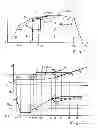
FIG. 1 a correction according to the invention of torque deficiency of a turbo-charged internal combustion engine occurring during travel in an engine characteristic map,
FIG. 2 relevant speed and torque progression for the example in FIG. 1,
FIG. 3 an engine dynamics characteristic map of a turbo-charged internal combustion engine,
FIG. 4a the torque build-up of an internal combustion engine according to FIG. 4 with an engine speed controlled below the boost threshold speed, thus (nM≦nL—min), and
FIG. 4b the torque build-up of an internal combustion engine according to FIG. 4 with an engine speed controlled above the boost threshold speed, thus (nM>nL—min).
DETAILED DESCRIPTION OF THE PREFERRED EMBODIMENTS
A presently assumed drive train of a commercial vehicle comprises a drive engine designed as a turbo-charged internal combustion engine, a startup and shifting clutch designed as an automated friction clutch, and a transmission designed as an automatic stepped transmission.
The stepped transmission can be connected on the input side, via the friction clutch, to the drive shaft (crankshaft) of the internal combustion engine, and is connected on the output side, via a cardan shaft, to the axle transmission (axle differential) of a drive axle. At least one auxiliary consumer and optionally at least one drive-side power take-off are disposed at the internal combustion engine, which, in the driven state, reduce the engine torque MM from the internal combustion engine that can be delivered at the friction clutch and that is available for driving the motor vehicle. In addition, further output drive-side power take-offs can be disposed at the stepped transmission or at the axle transmission, which, in the activated state, further reduce the engine torque MM transmitted, via the friction clutch, to the stepped transmission, such that in driving operation a correspondingly reduced torque is available for overcoming the drive resistance and attaining at least minimal vehicle acceleration.
In drive operation, the internal combustion engine must therefore be able to generate engine torque MM and deliver the torque at the friction clutch so that such torque, minus the drive torques for the auxiliary consumers and the drive-side power take-offs, is sufficient for attaining acceptable vehicle acceleration. For this purpose, the engine torque MM transferred by the friction clutch must be high enough that, even minus the drive torques for the output-drive-side power take-offs, the engine torque exceeds the drive resistance torque resulting from the present drive resistance, that is, the reduced drive resistance torque MFW reduced with the overall transmission ratio and the efficiency of the drive train at the input shaft of the stepped transmission, to such a degree that the excess torque is at least sufficient for minimal vehicle acceleration.
The present invention proposes a method with which torque deficiency of the drive engine during travel is overcome, this torque deficiency occurring when the driver demands power corresponding to a target torque Msoll of the drive engine which is above the spontaneously attainable maximum torque Mmax, without a downshift or a startup from standstill having to be performed.
For this purpose, the important dynamic operating characteristics of the drive engine built as a turbo-charged internal combustion engine, can be taken from the engine dynamics characteristic map known from the document DE 10 2008 054 802.2, which can be stored in the data store of the transmission control unit and is shown for example in FIG. 3.
The engine dynamics characteristic map, shown in FIG. 3 in a torque—speed diagram, contains the spontaneously available maximum torque Mmax of the internal combustion engine and the maximum torque gradient (dMM/dt)max, with which the spontaneously available maximum torque Mmax of the internal combustion engine can be attained as quickly as possible, in each case as a function of the present engine torque MM and the present engine speed nM, thus (Mmax=f(MM, nM), (dMM/dt)max=f(MM, nM)).
The engine dynamics characteristic map is bounded by the steady-state full load torque characteristic curve MVL(nM), the zero torque curve (MM=0), the idle speed nidle and the cut-off speed nlim of the internal combustion engine. The engine dynamics characteristic map is subdivided into four operating regions A, B, C, D by the intake torque characteristic curve MS(nM) of the intake torque, simplified here as assumed to be constant MS=const., and the boost threshold speed nL—min of the internal combustion engine.
In the first operating region A (0≦MM<MS, nidle≦nM<nL—min) that is below the intake torque characteristic curve MS=const. and below the boost threshold speed nL—min, the spontaneously available maximum torque Mmax(nM) of the internal combustion engine is formed in each case by the corresponding value of the intake torque MS, thus (Mmax(nM)=MS). However, as the intake torque MS in this region is constant (MS=const.), the spontaneously available maximum torque Mmax of the internal combustion engine is represented by a single value (Mmax=MS=const.). Independent of this, the very high maximum torque gradient (dMM/dt)max in operating region A can also be represented by a single value.
In the second operating region B (0≦MM<Ms, nL—min≦nM≦nlim) lying below the intake torque characteristic curve MS=const. and above the boost threshold speed nL—min, the spontaneously available maximum torque Mmax(nM) of the internal combustion engine is similarly given in each case by the corresponding value of the intake torque MS. Because the intake torque MS in this region has a constant progression (MS=const.), the spontaneously available maximum torque Mmax of the internal combustion engine in operating region B is likewise represented by a single value (Mmax=MS=const.). As with operating region A, the very high maximum torque gradient (dMM/dt)max beneath the intake torque characteristic curve MS=const. can also be expressed by a single value in operating region B.
In the third operating region C (Ms≦MM<MVL(nM), nL—min≦nM ≦nlim), adjacent to operating region B and lying above the intake torque characteristic curve MS=const. and above the boost threshold speed nL—min, a further increase of the engine torque MM is possible up to the respective value of the steady-state full load torque characteristic curve MVL(nM), however, with a significantly lower maximum torque gradient (dMM/dt)max than in operating regions A and B, i.e., below the intake torque characteristic curve MS=const.
In the fourth operating region D (MS≦MM<MVL(nM), nidle≦nM<nL—min), adjoining at the first region A, above the intake torque characteristic curve MS=const. and below the boost threshold speed nL—min, a further rapid increase of the engine torque MM is not possible without an increase of the engine speed nM above the boost threshold speed nL—min. Consequently, in operating region D, the spontaneously available maximum torque Mmax(nM) of the internal combustion engine equals the corresponding value of the intake torque MS, thus (Mmax(nM)=MS=const.) and the maximum torque gradient (dMM/dt)max equals zero, thus ((dMM/dt)max=0).
An operating region E, which cannot be attained in normal driving operation and thus is not relevant, can be defined above the full load torque characteristic curve MVL(nM). Below the full load torque characteristic curve MVL(nM) and the idle speed nidle, there is an undesirable but technically attainable operating region F, into which the internal combustion engine can be pushed dynamically in regard to its operating behavior from an engine speed nM lying near the idle speed nidle, for example due to a rapid engagement of the friction clutch, and in which there is a danger of stalling the internal combustion engine.
In addition, a nearby region lying immediately below the full load torque characteristic curve MVL(nM) can be defined as an additional operating region V, in which the internal combustion engine under full load, that is along the full load torque characteristic curve MVL(nM), can be pushed to a lower engine speed nM or controlled to higher engine speed nM.
For the driving states considered here, in which the drive engine is to be guided from an engine speed nM lying below the boost threshold speed nL—min to an engine speed nM lying above the boost threshold speed nL—min, and from an engine torque MM lying below the intake torque MS to an engine torque MM lying above the intake torque MS, it is to be noted accordingly that the drive engine can be spontaneously loaded, that is with a high torque gradient dMM/dt, only up to the intake torque MS when the engine speed nM remains below the boost threshold speed nL—min. This relationship is illustrated in a greatly simplified manner in the torque progression MM(t) in image insert (a) of FIG. 3 and in the time progression of FIG. 4a.
Likewise it is to be noted for the present drive control that the drive engine must be accelerated above the boost threshold speed nL—min in order to spontaneously set an engine torque MM lying above the intake torque MS, that is, it must be controlled from operating region A into operating region B or C, because a further rapid increase of the engine torque MM is possible only above the boost threshold speed nL—min, even with a lower torque gradient dMM/dt. This relationship is illustrated in a greatly simplified manner in the torque progression MM(t) in image insert (b) of FIG. 3 and in the time progression of FIG. 4b.
The present method for drive control according to the invention provides that remedying a torque deficiency of the drive engine depending on the dynamic operating properties thereof occurs such that initially the friction clutch is disengaged up to the transition into slipping operation until the drive engine has accelerated up to the boost threshold speed nL—min or an engine speed nM lying slightly above the boost threshold speed nL—min, thus (nM=nL—min; nM=nL—min+ΔnM). Next, the drive engine is then loaded up to nearly the full load torque MVL(nL—min) with a largely constant engine speed (nM≈nL—min) by an appropriate increase of the engine power and by an engagement of the friction clutch coordinated therewith before the slipping operation of the friction clutch ends.
Three variants of a corresponding speed and torque guidance of the internal combustion engine are shown in FIG. 1 in an engine dynamics characteristic map according to FIG. 3 and in FIGS. 2a) and b) with the respective time progressions of the engine speed nM, the transmission input speed nGE and the engine torque MM.
Starting from a drive operating state with high engine torque MM and relatively low engine speed nM at the time t0” (operating point P2), the power requested by the driver is reduced significantly by reducing the gas pedal setting or by releasing the gas pedal such that the engine torque MM at a largely constant engine speed nM decreases below the intake torque MS up to time t0′ (operating point P0).
When the driver again shortly thereafter (at time t0) requests power at the old level or beyond that by an appropriate gas pedal setting, the drive engine can quickly increase the engine torque MM, that is, at high torque gradient dMM/dt, due to the dynamic operating properties thereof, only up to the intake torque Ms (operating point P1, time t1).
An increase of the engine torque MM to the previous level at operating point P2, shown in FIG. 1 with a dashed line, is then not possible, such that normally a downshift associated with an interruption of the tractive force or even startup from standstill would be required. At the latest in this operation situation, the method according to the invention is activated in order to overcome the torque deficiency of the drive engine without performing a downshift or a startup from standstill.
For this purpose, initially the friction clutch at time t1 is disengaged up to the transition into the slipping operation, whereby the drive engine is accelerated until exceeding the boost threshold speed nL—min, (operating point P1′, time t1′). Then, the drive engine is loaded by a corresponding increase of the engine power at a largely constant engine speed (nM≈nL—min) up to nearly full load torque MVL(nL—min) and by a coordinated engagement of the friction clutch (operating point P1″, time t2), whereby in the meantime the engine torque MM at time t1″ exceeds the drive resistance torque MFW, and consequently the motor vehicle and the input shaft of the stepped transmission are accelerated, that is, the transmission input speed nGE increases.
With the attainment of operating point P1″ near to the full load torque MVL(nL—min), three possibilities arise for ending the slipping operation of the fiction clutch and transitioning into normal driving operation.
In a relatively uncomfortable first variant of the method, however with low thermal loading of the friction clutch, the engine speed nM is reduced to the transmission input speed nGE by further engagement of the friction clutch and/or by intervention in the engine control, (nM=nGE, nM<nLmin whereby the engine torque MM is reduced, thus (MM<MVL(nL—min)) and the engine speed nM is reduced below the boost threshold speed nL—min, thus (nM<nL—min) (operating point P2′, time t3). Then the friction clutch is completely engaged and transitioned into normal driving operation control.
In a comfortable second variant of the method, however with higher thermal loading of the friction clutch, the drive engine is held at the present engine speed (nM=nL—min) and the friction clutch is held at the present degree of disengagement until synchronous running (nM=nGE) is achieved at the friction clutch, and thereupon the friction clutch is completely engaged (operating point P2″, time t3′).
In an also comfortable third variant of the method, however with even higher thermal loading of the friction clutch, the drive engine is set to a higher engine speed (nM>nL—min) and a higher engine torque (MM>MVL(nL—min) by increasing the engine power and by further engagement of the friction clutch (operating point P1′″, time t2′) and held there until synchronous running (nM=nGE) has been achieved at the friction clutch (operating point P2′−, time t3″),after which the friction clutch is completely engaged.
The variant of the method used can be fixed in a vehicle-specific or use-specific manner, or selected depending on present operating parameters, particularly in the relation of the engine torque (MM=MVL(nL—min)) present at operating point P1″ to the target torque Msoll, requested by the driver.
Reference Characters
- A operating region
- B operating region
- C operating region
- D operating region
- E operating region
- F operating region
- M torque
- MFW drive resistance torque
- MM engine torque
- Mmax maximum torque
- MS intake torque
- Msoll target torque
- MVL full load torque
- n rotational speed
- nGE transmission input speed
- nidle idle speed
- nL—min boost threshold speed
- nlim cut-off speed
- nM engine speed
- p pressure
- pL charge pressure
- PL—min boost threshold value
- P0 operating point
- P1 operating point
- P1′ operating point
- P1″ operating point
- P1′″ operating point
- P2 operating point
- P2′ operating point
- P2″ operating point
- P2′″ operating point
- t time
- t0 point in time
- t0′ point in time
- t0″ point in time
- t1 point in time
- t1′ point in time
- t1″ point in time
- t2 point in time
- t2′ point in time
- t3 point in time
- t3′ point in time
- t3″ point in time
- V operating region
- ΔnM increase in speed
Claims
1-19. (canceled)
20. A method for the drive control of a motor vehicle having a drive train which comprises a drive engine built as a turbo-charged internal combustion engine, a startup and shifting clutch built as an automated friction clutch, and a transmission built as an automatic stepped transmission, such that torque deficiency of the drive engine that occurs during travel is overcome, which torque deficiency occurs when a driver demands power corresponding to a target torque (Msoll) of the drive engine which is above a spontaneously attainable maximum torque (Mmax), the method comprising the steps of:
initially disengaging the friction clutch up to transitioning into a slipping operation,
accelerating the drive engine to either a boost threshold speed (nL—min) or an engine speed (nM) which is slightly above the boost threshold speed ((nL—min), (nM=nL min; nM=nL—minΔnM)), and
loading the drive engine up to nearly a full load torque (MVL(nL—min)) with a substantially constant engine speed (nM =nL—min) before the slipping operation of the friction clutch ends.
21. The method according to claim 20, further comprising the steps of lowering the engine speed (nM) to a transmission input speed ((nGE), (nM=nGE, nM<nL—min)), by at least one of further engagement of the friction clutch and intervention in the engine control, and then completely engaging the friction clutch.
22. The method according to claim 21, further comprising the step of performing the method when a present engine torque (MM(nL—min)) lies significantly above the target torque (Msoll) of the drive engine (MM(nL—min)>>Msoll).
23. The method according to claim 20, further comprising the step of holding the drive engine at a present engine speed (nM=nL—min) and holding the friction clutch at a present degree of disengagement until reaching synchronous running (nM=nGE) at the friction clutch, and then completely engaging the friction clutch.
24. The method according to claim 23, further comprising the step of performing the method when a present engine torque (MM(nL—min)) either substantially corresponds to the target torque (Msoll) of the drive engine, or lies slightly above the target torque (Msoll) of the drive engine ((MM(nL—min)≦Msoll).
25. The method according to claim 20, further comprising the step of setting the drive engine to a higher engine speed (nM>nmin) and a higher engine torque (MM>MVL(nL—min)) by increasing engine power and by further engagement of the friction clutch, and holding there until the friction clutch runs synchronously (nM=nGE), and then completely engaging the friction clutch.
26. The method according to claim 23, further comprising the step of setting the drive engine to a higher engine speed (nM>nL—min) and a higher engine torque (MM>MVL(nL—min)) by increasing engine power and by further engagement of the friction clutch, and holding there until the friction clutch runs synchronously (nM=nGE), and then completely engaging the friction clutch; and
performing the method when a present engine torque (MM(nL—min)) lies significantly below the target torque (Msoll) of the drive engine (MM(nL—min)<<Msoll).
27. The method according to claim 20, further comprising the step of detecting either an existing or an immediately impending torque deficiency of the drive engine by the fact that the present engine torque (MM) is either less than or equal to the intake torque (MS) of the drive engine (MM≦MS), that a present engine speed (nM) is less than the boost threshold speed (nL—min) of the drive engine (nM<nL—min), and that the target torque (M) of the drive engine lies above the intake torque (MS) of the drive engine (Msoll>MS).
28. The method according to claim 20, further comprising the step of detecting either an existing or an immediately impending torque deficiency of the drive engine by the fact that a present drive resistance torque (MFW) being greater than the spontaneously attainable maximum torque (Mmax) of the drive engine (MFW>Mmax), and that the target torque (Msoll) of the drive engine lies above the present drive resistance torque ((MFW), (Msoll>MFW)).
29. The method according to claim 20, further comprising the step of detecting either an existing or an immediately impending torque deficiency of the drive engine by the fact that a present charge pressure (pL) of the drive engine is less than a boost threshold value (pL—min) characterizing an exhaust gas turbo-charger for a charge build-up, thus (pL<pL—min), and that the drive engine, for creating the target torque (Msoll), requires a charge pressure (pL≧pL—min) lying above the boost threshold value ((pL—min), (Msoll>MS)).
30. The method according to claim 20, further comprising the step of determining an engine torque (MVL(nM)) that is attainable using the drive control ahead of time, and performing the drive control only when the attainable engine torque (MVL(nM)) corresponds at least to a present drive resistance torque ((MFW), (MVL(nM)≧MFW)).
31. The method according to claim 30, further comprising the step of determining the engine torque (MM(nM)) that is attainable using the drive control from a full load characteristic curve of the drive engine as the full load torque (MVL(nM)) that can be set at the present engine speed (nM).
32. The method according to claim 20, further comprising the step of determining a thermal loading of the friction clutch caused by the drive control ahead of time, and performing the drive control only when the thermal loading of the friction clutch does not exceed a specified load limit value.
33. The method according to claim 20, further comprising the step of performing the drive control only when a presently engaged gear does not exceed a predetermined maximum gear.
34. The method according to claim 20, further comprising the step of performing the drive control only when another lower gear for a downshift is unavailable.
35. The method according to claim 20, further comprising the step of performing the drive control only when a presently engaged gear corresponds to a startup gear intended under present operating and environmental conditions.
36. The method according to claim 20, further comprising the step of performing the drive control only when a downshift under present operating and environmental conditions would lead to a vehicle standstill and a subsequent startup.
37. The method according to claim 20, further comprising the step of performing the drive control only when a gas pedal setting has attains or exceeds a predetermined limit setting.
38. The method according to claim 20, further comprising the step of performing the drive control only when the drive control is released as either a vehicle-specific or a use-specific special function.
39. A method of controlling drive of a motor vehicle to increase torque when a driver demands a target torque (Msoll) of a drive engine which is above a spontaneously attainable maximum torque (Mmax) of the drive engine, a drive train of the motor vehicle comprises a turbo-charged internal combustion engine as the drive engine, an automated friction clutch, and an automatic stepped transmission, the method comprising the steps of:
disengaging the friction clutch such that the friction clutch operates in a slip operation;
accelerating the drive engine to either a load threshold speed (nL—min) or an engine speed (nM) which is slightly above the load threshold speed (nL—min);
loading the drive engine up to substantially a full load torque (MVL(nL—min)) with a substantially constant engine speed (nM≈nL—min); and
terminating the slipping operation of the friction clutch.
Images & Drawings included:


Sources:
- United States Patent and Trademark Office - verify current appl. status at the USPTO↗
Recent applications in this class:
- » 20130283782 2013-10-31
Method for diagnosing an engine - » 20130184966 2013-07-18
Method and system for engine torque control - » 20130067915 2013-03-21
Methods and systems for diagnosing a turbocharger - » 20130067914 2013-03-21
Methods and systems for diagnosing a turbocharger - » 20130060450 2013-03-07
Method and device for performing a control, in particular for use in a motor vehicle - » 20130047956 2013-02-28
Control system and method for preventing stochastic pre-ignition in an engine - » 20130042611 2013-02-21
Combustion control apparatus for an internal combustion engine - » 20130013166 2013-01-10
DETERMINATION OF EXHAUST BACK PRESSURE
Recent applications for this Assignee:
- » 20250293169 2025-09-18
STACKABLE POWER SEMICONDUCTOR MODULE - » 20250292970 2025-09-18
CAPACITIVE WINDING OF A DC LINK CAPACITOR AND DC LINK CAPACITOR WITH A COMMON-MODE CURRENT LEAKAGE FUNCTION - » 20250286013 2025-09-11
APPARATUS AND METHOD FOR MANUFACTURING A POWER SEMICONDUCTOR DEVICE - » 20250283529 2025-09-11
DRIVE UNIT FOR A VEHICLE - » 20250282215 2025-09-11
MOTOR VEHICLE TRANSMISSION FOR AN AT LEAST PARTIALLY ELECTRICALLY DRIVEN MOTOR VEHICLE - » 20250282209 2025-09-11
DRIVE UNIT FOR A VEHICLE - » 20250269709 2025-08-28
ARTICULATED RIGID AXLE OF A VEHICLE WITH AN AXLE SUPPORT WITH AN ELECTRIC MACHINE AS DRIVE - » 20250262892 2025-08-21
AXLE SUPPORT SYSTEM FOR A VEHICLE AXLE - » 20250256806 2025-08-14
BATTERY TERMINAL FOR TWO-WHEELED VEHICLES HAVING AN ELECTRIC DRIVE UNIT - » 20250251033 2025-08-07
GEARBOX AND DRIVE UNIT WITH SUCH A GEARBOX