System and method for high-performance, low-power data center interconnect fabric with addressing and unicast routing
US20130044587A1
2013-02-21
13/624,725
2012-09-21
✅ Patent granted
US 9,405,584 B2
2016-08-02
-
-
Mark Rinehart | Kenneth P Hunt
2032-09-21
Abstract:
A system and method are provided that support a routing using a tree-like or graph topology that supports multiple links per node, where each link is designated as an Up, Down, or Lateral link, or both, within the topology. The system may use a segmented MAC architecture which may have a method of re-purposing MAC IP addresses for inside MACs and outside MACs, and leveraging what would normally be the physical signaling for the MAC to feed into the switch.
Inventors:
- Mark Davis 18 🇺🇸 Austin, TX, United States
- David James Borland 25 🇺🇸 Austin, TX, United States
Assignee:
- Calxeda, inc. 24 🇺🇸 Austin, TX, United States
- III HOLDINGS 2, LLC 94 🇺🇸 WILMINGTON, DE, United States
Applicant:
Interested in similar patents?
Get notified when new applications in this technology area are published.
Classification:
H04L45/74 » CPC main
Routing or path finding of packets in data switching networks Address processing for routing
G06F3/0605 » CPC further
Input arrangements for transferring data to be processed into a form capable of being handled by the computer; Output arrangements for transferring data from processing unit to output unit, e.g. interface arrangements; Digital input from, or digital output to, record carriers, e.g. RAID, emulated record carriers or networked record carriers; Interfaces specially adapted for storage systems specifically adapted to achieve a particular effect; Improving or facilitating administration, e.g. storage management by facilitating the interaction with a user or administrator
G06F3/0631 » CPC further
Input arrangements for transferring data to be processed into a form capable of being handled by the computer; Output arrangements for transferring data from processing unit to output unit, e.g. interface arrangements; Digital input from, or digital output to, record carriers, e.g. RAID, emulated record carriers or networked record carriers; Interfaces specially adapted for storage systems making use of a particular technique; Configuration or reconfiguration of storage systems by allocating resources to storage systems
G06F3/067 » CPC further
Input arrangements for transferring data to be processed into a form capable of being handled by the computer; Output arrangements for transferring data from processing unit to output unit, e.g. interface arrangements; Digital input from, or digital output to, record carriers, e.g. RAID, emulated record carriers or networked record carriers; Interfaces specially adapted for storage systems adopting a particular infrastructure Distributed or networked storage systems, e.g. storage area networks [SAN], network attached storage [NAS]
G06F1/3234 » CPC further
Details not covered by groups - and; Power supply means, e.g. regulation thereof; Means for saving power; Power management, i.e. event-based initiation of a power-saving mode Power saving characterised by the action undertaken
G06F12/0284 » CPC further
Accessing, addressing or allocating within memory systems or architectures; Addressing or allocation; Relocation; User address space allocation, e.g. contiguous or non contiguous base addressing Multiple user address space allocation, e.g. using different base addresses
H04L49/201 » CPC further
Packet switching elements; Support for services Multicast operation; Broadcast operation
H04L49/253 » CPC further
Packet switching elements; Routing or path finding in a switch fabric using establishment or release of connections between ports
Y02B70/10 » CPC further
Technologies for an efficient end-user side electric power management and consumption Technologies improving the efficiency by using switched-mode power supplies [SMPS], i.e. efficient power electronics conversion e.g. power factor correction or reduction of losses in power supplies or efficient standby modes
Y02B70/30 » CPC further
Technologies for an efficient end-user side electric power management and consumption Systems integrating technologies related to power network operation and communication or information technologies for improving the carbon footprint of the management of residential or tertiary loads, i.e. smart grids as climate change mitigation technology in the buildings sector, including also the last stages of power distribution and the control, monitoring or operating management systems at local level
Y02D10/00 » CPC further
Energy efficient computing, e.g. low power processors, power management or thermal management
Y02D10/00 » CPC further
Energy efficient computing, e.g. low power processors, power management or thermal management
Y02D30/00 » CPC further
Reducing energy consumption in communication networks
Y02D30/00 » CPC further
Reducing energy consumption in communication networks
G06F9/5016 » CPC main
Arrangements for program control, e.g. control units using stored programs, i.e. using an internal store of processing equipment to receive or retain programs; Multiprogramming arrangements; Allocation of resources, e.g. of the central processing unit [CPU] to service a request the resources being hardware resources other than CPUs, Servers and Terminals the resource being the memory
G06F13/40 » CPC further
Interconnection of, or transfer of information or other signals between, memories, input/output devices or central processing units; Information transfer, e.g. on bus Bus structure
H04L45/00 » CPC further
Routing or path finding of packets in data switching networks
H04L45/60 » CPC further
Routing or path finding of packets in data switching networks Router architectures
H04L49/109 » CPC further
Packet switching elements characterised by the switching fabric construction Integrated on microchip, e.g. switch-on-chip
H04L49/15 » CPC further
Packet switching elements Interconnection of switching modules
H04L49/25 » CPC further
Packet switching elements Routing or path finding in a switch fabric
H04L49/3009 » CPC further
Packet switching elements; Peripheral units, e.g. input or output ports Header conversion, routing tables or routing tags
H04L49/351 » CPC further
Packet switching elements; Switches specially adapted for specific applications for local area network [LAN], e.g. Ethernet switches
H04L49/356 » CPC further
Packet switching elements; Switches specially adapted for specific applications for storage area networks
H04L47/10 » CPC further
Traffic control in data switching networks Flow control; Congestion control
H04L12/28 IPC
Data switching networks characterised by path configuration, e.g. LAN [Local Area Networks] or WAN [Wide Area Networks]
G06F9/50 IPC
Arrangements for program control, e.g. control units using stored programs, i.e. using an internal store of processing equipment to receive or retain programs; Multiprogramming arrangements Allocation of resources, e.g. of the central processing unit [CPU]
G06F13/24 » CPC further
Interconnection of, or transfer of information or other signals between, memories, input/output devices or central processing units; Handling requests for interconnection or transfer for access to input/output bus using interrupt
G06F1/32 IPC
Details not covered by groups - and; Power supply means, e.g. regulation thereof Means for saving power
G06F13/00 » CPC further
Interconnection of, or transfer of information or other signals between, memories, input/output devices or central processing units
Description
PRIORITY CLAIMS/RELATED APPLICATIONS
This patent application is a divisional of and claims priority under 35 USC 120 and 121 to U.S. patent application Ser. No. 12/794,996 filed on Jun. 7, 2010 which in turn claims the benefit under 35 USC 119(e) to U.S. Provisional Patent Application Ser. No. 61/256,723 filed on Oct. 30, 2009 and entitled “System and Method for Enhanced Communications in a Multi-Processor System of a Chip (SOC), which are both incorporated herein by reference.
FIELD
The disclosure relates generally to a switching fabric for a computer-based system.
BACKGROUND
With the continued growth of the internet, web-based companies and systems and the proliferation of computers, there are numerous data centers that house multiple server computers in a location that is temperature controlled and can be externally managed as is well known.
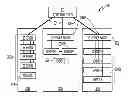
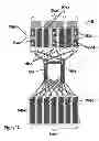
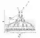
FIGS. 1A and 1B show a classic data center network aggregation as is currently well known. FIG. 1A shows a diagrammatical view of a typical network data center architecture 100 wherein top level switches 101a-n are at the tops of racks 102a-n filled with blade servers 107a-n interspersed with local routers 103a-f. Additional storage routers and core switches. 105a-b and additional rack units 108a-n contain additional servers 104e-k and routers 106a-g FIG. 1b shows an exemplary physical view 110 of a system with peripheral servers 111a-bn arranged around edge router systems 112a-h, which are placed around centrally located core switching systems 113. Typically such an aggregation 110 has 1-Gb Ethernet from the rack servers to their top of rack switches, and often 10 Gb Ethernet ports to the edge and core routers.
However, what is needed is a system and method for packet switching functionality focused on network aggregation that reduces size and power requirements of typical systems while reducing cost all at the same time and it is to this end that the disclosure is directed.
BRIEF DESCRIPTION OF THE DRAWINGS
FIGS. 1A and 1B illustrate a typical data center system;
FIG. 2 is an overview of a network aggregation system;
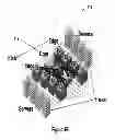
FIG. 3 illustrates an overview of an exemplary data center in a rack system;
FIG. 4 illustrates a high-level topology of a network aggregating system;
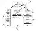
FIG. 5A illustrates a block diagram of an exemplary switch of the network aggregation system;
FIG. 5B illustrates the MAC address encoding;
FIG. 6 illustrates a first embodiment of a broadcast mechanism of the network aggregation system;
FIG. 7 illustrates an example of unicast routing of the network aggregation system;
FIG. 8 illustrates an example of fault-resistant unicast routing of the network aggregation system; and
FIG. 9 illustrates a second embodiment of a broadcast mechanism of the network aggregation system.
DETAILED DESCRIPTION OF ONE OR MORE EMBODIMENTS
The disclosure is particularly applicable to a network aggregation system and method as illustrated and described below and it is in this context that the disclosure will be described. It will be appreciated, however, that the system and method has greater utility since the system and method can be implemented using other elements and architectures that are within the scope of the disclosure and the disclosure is not limited to the illustrative embodiments described below.
The system and method also supports a routing using a tree-like or graph topology that supports multiple links per node, where each link is designated as an Up, Down, or Lateral link, or both, within the topology. In addition, each node in the system maybe be a combination computational/switch node, or just a switch node, and input/outpout (I/O) can reside on any node as described below in more detail. The system may also provide a system with a segmented Ethernet Media Access Control (MAC) architecture which may have a method of re-purposing MAC IP addresses for inside MACs and outside MACs, and leveraging what would normally be the physical signaling for the MAC to feed into the switch. The system may also provide a method of non-spoofing communication, as well as a method of fault-resilient broadcasting, which may have a method of unicast misrouting for fault resilience. In the context of network security, a spoofing attack is a situation in which one person or program successfully masquerades as another by falsifying data and thereby gaining an illegitimate advantage.
The system may also provide a rigorous security between the management processors, such that management processors can “trust” one another. In the example system shown in FIG. 5A (which is described below in more detail), there is a management processor within each SoC (the M3 microcontroller, block 906, FIG. 5A). The software running on the management processor is trusted because a) the vendor (in this case Smooth-Stone) has developed and verified the code, b) non-vendor code is not allowed to run on the processor. Maintaining a Trust relationship between the management processors allow them to communicate commands (e.g. reboot another node) or request sensitive information from another node without worrying that a user could spoof the request and gain access to information or control of the system.
The system may also provide a network proxy that has an integrated microcontroller in an always-on power domain within a system on a chip (SOC) that can take over network proxying for the larger onboard processor, and which may apply to a subtree. The system also provide a multi-domaining technique that can dramatically expand the size of a routable fat tree like structure with only trivial changes to the routing header and the routing table.
FIG. 2 illustrates a network aggregation system 300. The network aggregation supports one or more high speed links 301 (thick lines), such as a 10-Gb/sec Ethernet communication, that connect an aggregation router 302 and one or more racks 303, such as three racks 303a-c as shown in FIG. 3. In a first rack 303a, the network aggregation system provides multiple high-speed 10 Gb paths, represented by thick lines, between one or more Smooth-Stone computing unit 306a-d, such as server computers, on shelves within a rack. Further details of each Smooth-Stone computing unit are described in more detail in U.S. Provisional Patent Application Ser. No. 61/256,723 filed on Oct. 30, 2009 and entitled “System and Method for Enhanced Communications in a Multi-Processor System of a Chip (SOC)” which is incorporated herein in its entirety by reference. An embedded switch 306a-d in the Smooth-Stone computing units can replace a top-of-rack switch, thus saving a dramatic amount of power and cost, while still providing a 10 Gb Ethernet port to the aggregation router 302. The network aggregation system switching fabric can integrate traditional Ethernet (1 Gb or 10 Gb) into the XAUI fabric, and the Smooth-Stone computing units can act as a top of rack switch for third-party Ethernet connected servers.
A middle rack 303b illustrates another configuration of a rack in the network aggregation system in which one or more Smooth-Stone computing units 306e, f can integrate into existing data center racks that already contain a top-of-rack switch 308a. In this case, the IT group can continue to have their other computing units connected via 1 Gb Ethernet up to the existing top-of-rack switch and the internal Smooth-Stone computing units can be connected via 10 Gb XAUI fabric and they can integrate up to the existing top-of-rack switch with either a 1 Gb or 10 Gb Ethernet interconnects as shown in FIG. 2. A third rack 303c illustrates a current way that data center racks are traditionally deployed. The thin red lines in the third rack 303c represent 1 Gb Ethernet. Thus, the current deployments of data center racks is traditionally 1 Gb Ethernet up to the top-of-rack switch 308b, and then 10 Gb (thick red line 301) out from the top of rack switch to the aggregation router. Note that all servers are present in an unknown quantity, while they are pictured here in finite quantities for purposes of clarity and simplicity. Also, using the enhanced SS servers, no additional routers are needed, as they operate their own XAUI switching fabric, discussed below.
FIG. 3 shows an overview of an exemplary “data center in a rack” 400 according to one embodiment of the system. The “data center in a rack” 400 may have 10-Gb Ethernet PHY 401a-n and 1-Gb private Ethernet PHY 402. Large computers (power servers) 403a-n support search; data mining; indexing; Apache Hadoop, a Java software framework; MapReduce, a software framework introduced by Google to support distributed computing on large data sets on clusters of computers; cloud applications; etc. Computers (servers) 404a-n with local flash and/or solid-state disk (SSD) support search, MySQL, CDN, software-as-a-service (SaaS), cloud applications, etc. A single, large, slow-speed fan 405 augments the convection cooling of the vertically mounted servers above it. Data center 400 has an array 406 of hard disks, e.g., in a Just a Bunch of Disks (JBOD) configuration, and, optionally, Smooth-Stone computing units in a disk form factor (for example, the green boxes in arrays 406 and 407), optionally acting as disk controllers. Hard disk servers or SS disk servers may be used for web servers, user applications, and cloud applications, etc. Also shown are an array 407 of storage servers and historic servers 408a, b (any size, any vendor) with standard Ethernet interfaces for legacy applications.
The data center in a rack 400 uses a proprietary system interconnect approach that dramatically reduces power and wires and enables heterogeneous systems, integrating existing Ethernet-based servers and enabling legacy applications. In one aspect, a complete server or storage server is put in a disk or SSD form factor, with 8-16 SATA interfaces with 4 ServerNodes™ and 8 PCIe x4 interfaces with 4 ServerNodes™. It supports disk and/or SSD+ServerNode™, using a proprietary board paired with a disk(s) and supporting Web server, user applications, cloud applications, disk caching, etc.
The Smooth-Stone XAUI system interconnect reduces power, wires and the size of the rack. There is no need for high powered, expensive Ethernet switches and high-power Ethernet Phys on the individual servers. It dramatically reduces cables (cable complexity, costs, significant source of failures). It also enables a heterogeneous server mixture inside the rack, supporting any equipment that uses Ethernet or SATA or PCIe. It can be integrated into the system interconnect.
The herein presented aspects of a server-on-a-chip (SOC) with packet switch functionality are focused on network aggregation. The SOC is not a fully functionally equivalent to an industry-standard network switch, such as, for example, a Cisco switch or router. But for certain applications discussed throughout this document, it offers a better price/performance ratio as well as a power/performance ratio. It contains a layer 2 packet switch, with routing based on source/destination MAC addresses. It further supports virtual local area network (VLAN), with configurable VLAN filtering on domain incoming packets to minimize unnecessary traffic in a domain. The embedded MACs within the SOC do have complete VLAN support providing VLAN capability to the overall SOC without the embedded switch explicitly having VLAN support. It can also wake up the system by management processor notifying the management processor on link state transitions to reprogram routing configurations to route around faults. Such functionality does not require layer 3 (or above) processing (i.e., it is not a router). It also does not offer complete VLAN support, support for QoS/CoS, address learning, filtering, spanning tree protocol (STP), etc.
FIG. 4 shows a high-level topology 800 of the network system that illustrates XAUI connected SoC nodes connected by the switching fabric. The 10 Gb Ethernet ports Eth0 801a and Eth1 801b come from the top of the tree. Ovals 802a-n are Smooth-Stone nodes that comprise both computational processors as well as the embedded switch. The nodes have five XAUI links connected to the internal switch. The switching layers use all five XAUI links for switching. Level 0 leaf nodes 802d, e (i.e., N0n nodes, or Nxy, where x=level and y=item number) only use one XAUI link to attach to the interconnect, leaving four high-speed ports that can be used as XAUI, 10 Gb Ethernet, PCIe, SATA, etc., for attachment to I/O. The vast majority of trees and fat trees have active nodes only as leaf nodes, and the other nodes are pure switching nodes. This approach makes routing much more straightforward. Topology 800 has the flexibility to permit every node to be a combination computational and switch node, or just a switch node. Most tree-type implementations have I/O on the leaf nodes, but topology 800 let the I/O be on any node. In general, placing the Ethernet at the top of the tree minimizes the average number of hops to the Ethernet.
In more detail, the ovals shown in the tree-oriented topology in FIG. 6 represent independent nodes within a computing cluster. FIG. 5A illustrates one example implementation of an individual node of the cluster. When looking at a conventional implementation of a topology e.g. in FIG. 6, usually computing nodes are found in the lower level leaf nodes (e.g. N00-N08), and the upper level nodes don't have computing elements but are just network switching elements (N10-N21). With the node architecture shown in FIG. 6A, the A9 Cores (905) may be optionally enabled, or could be just left powered-off. So the upper level switching nodes (N10-N21) in FIG. 6 can be used as pure switching elements (like traditional implementations), or we can power on the A9 Cores module and use them as complete nodes within the computing cluster.
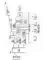
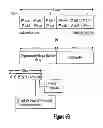
The switch architecture calls for a routing frame to be prepended to the Ethernet frame. The switch operates only against fields within the routing frame, and does not inspect the Ethernet frame directly. FIG. 5a shows a block diagram of an exemplary switch 900 according to one aspect of the system and method disclosed herein. It has four areas of interest 910a-d. Area 910a corresponds to Ethernet packets between the CPUs and the inside MACs. Area 910b corresponds to Ethernet frames at the Ethernet physical interface at the inside MACs, that contains the preamble, start of frame, and inter-frame gap fields. Area 910c corresponds to Ethernet frames at the Ethernet physical interface at the outside MAC, that contains the preamble, start of frame, and inter-frame gap fields. Area 910d corresponds to Ethernet packets between the processor of routing header 901 and outside MAC 904. This segmented MAC architecture is asymmetric. The inside MACs have the Ethernet physical signaling interface into the routing header processor, and the outside MAC has an Ethernet packet interface into the routing header processor. Thus the MAC IP is re-purposed for inside MACs and outside MACs, and what would normally be the physical signaling for the MAC to feed into the switch is leveraged. MAC configuration is such that the operating system device drivers of A9 cores 905 manage and control inside Eth0 MAC 902 and inside ETH1 MAC 903. The device driver of management processor 906 manages and controls Inside Eth2 MAC 907. Outside Eth MAC 904 is not controlled by a device driver. MAC 904 is configured in Promiscuous mode to pass all frames without any filtering for network monitoring. Initialization of this MAC is coordinated between the hardware instantiation of the MAC and any other necessary management processor initialization. Outside Eth MAC 904 registers are visible to both A9 905 and management processor 906 address maps. Interrupts for Outside Eth MAC 904 are routable to either the A9 or management processor. The XGMAC supports several interruptible events that the CPUs may want to monitor, including any change in XGMII link fault status, hot-plugging or removal of PHY, alive status or link status change, and any RMON counter reaching a value equal to the threshold register.
In some cases, there may be Preamble, Start of Frame, and Inter-Frame gap fields across XAUI, depending on the specific micro-architecture. The routing frame header processor may standardize these fields. The XAUI interface may need some or all of these fields. In this case, the routing header processor at area 910d needs to add these going into the switch, and to remove them leaving the switch. To reduce the number of bytes that need to be sent over XAUI, these three fields may be removed (if the XAUI interface allows it). In this case, the routing header processor at area 910b will need to strip these going into the switch, and add them back leaving the switch.
The routing frame header processor receives an Ethernet frame from a MAC, sending a routing frame to the switch. It also standardizes the preamble, start of frame, and inter-frame gap fields, prepends a routing header, and receives a routing frame from the switch, sending the Ethernet frame into a MAC. This processor then strips the routing header and standardizes the preamble, start of frame, and inter-frame gap fields. Note that all frames that are flowing within the fabric are routing frames, not Ethernet frames. The Ethernet frame/routing frame conversion is done only as the packet is entering or leaving the fabric via a MAC. Note also that the routing logic within the switch may change fields within the routing frame. The Ethernet frame is never modified (except the adding/removing of the preamble, start of frame, and inter-frame gap fields).
The routing frame is composed of the routing frame header plus the core part of the Ethernet frame, and is structured as shown in Table 1, below:
| TABLE 1 | |
| Routing | |
| Frame Header | Ethernet Frame Packet |
| RF | MAC | MAC | Ethertype/ | (data and | CRC32 |
| Header | destination | Source | Length | padding) | |
Note that the implementation assumptions for bit sizing are 4096 nodes→12 bit node IDs. These fields may be resized during implementation as needed.
The routing frame header consists of the fields shown in Table 2, below:
| TABLE 2 | ||
| Width | ||
| Field | (Bits) | Notes |
| Domain ID | 5 | Domain ID associated with this packet. 0 indicates |
| that no domain has been specified. | ||
| Mgmt Domain | 1 | Specifies that the packet is allowed on the private |
| management domain. | ||
| Source Node | 12 | Source node ID |
| Source Port | 2 | 0 = MAC0, 1 = MAC1, 2 = MAC_management |
| processor, 3 = MAC_OUT | ||
| Dest Node | 12 | Destination node ID |
| Dest Port | 2 | 0 = MAC0, 1 = MAC1, 2 = MAC_management |
| processor, 3 = MAC_OUT | ||
| RF Type | 2 | Routing Frame Type (0 = Unicast, 1 = Multicast, |
| 2 = Neighbor Multicast, 3 = Link Directed) | ||
| TTL | 6 | Time to Live - # of hops that this frame has existed. |
| Switch will drop packet if the TTL threshold is exceeded | ||
| (and notify management processor of exception). | ||
| Broadcast ID | 5 | Broadcast ID for this source node for this broadcast |
| packet. | ||
| Checksum | Checksum of the frame header fields. | |
| Total | 46 | +checksum |
If a switch receives a packet that fails the checksum, the packet is dropped, a statistic counter is incremented, and the management processor is notified.
The routing frame processor differentiates between several destination MAC address encodings. As a reminder, MAC addresses are formatted as shown in FIG. 5b. The following table describes the usage of the 3 byte OUI and 3 byte NIC specific field within the MAC address. One of the novel aspects of the system and method disclosed herein is the use of additional address bits to encode an internal to external MAC mapping, as shown also in the Table 3, below, in the second entry under “Fabric Internal Node local address Hits MAC Lookup CAM”.
| TABLE 3 | |||
| MAC Address | |||
| Type | 3 bytes OUI | 3 bytes NIC Specific | Operation |
| External | Multicast bit | Arbitrary | Packet unicast |
| Misses MAC | not set | routed to | |
| Lookup CAM | gateway node #. | ||
| Fabric Internal | Arbitrary | Node local address (meaning | Packet unicast |
| Node local | low 2 bits - port unit | routed to | |
| address | ID) are not present. MAC | fabric node # | |
| Hits MAC | Lookup CAM for entry | obtained from | |
| Lookup CAM | marked as Node Local. | MAC Lookup CAM | |
| Fabric Internal | Arbitrary | Arbitrary | Packet unicast |
| Arbitrary MAC | routed to | ||
| address | fabric node # | ||
| Hits MAC | obtained from | ||
| Lookup CAM | MAC Lookup CAM | ||
| Node Encoded | Unicast | 10 bits: | Packet |
| Unicast | Locally | SS_MAC_NODE_ENCODED_MAGIC | unicast |
| administered | 12 bits: Node ID | routed to | |
| OUI == Switch | 2 bits: Port ID | Node ID. | |
| OUI | |||
| Link Encoded | Unicast | 12 bits: | Packet sent |
| Unicast | Locally | SS_MAC_LINK_ENCODED_MAGIC | down specific |
| administered | 7 bits: Reserved | Link #. | |
| OUI == Switch | 3 bits: Link # (0-4) | ||
| OUI | 2 bits: Port | ||
| Multicast/ | Multicast bit | Arbitrary | Packet |
| Broadcast | set | broadcast | |
| routed through | |||
| fabric and | |||
| gateways. | |||
| Neighbor | Multicast bit | 12 bits: | Packet sent |
| Multicast | set | SS_NEIGHBOR_MCAST_MAGIC | through all |
| Locally | 12 bits: Reserved | XAUI links to | |
| administered | neighboring | ||
| OUI = Switch | nodes and not | ||
| OUI | rebroadcast | ||
| to other nodes | |||
Further, other novel aspects can be found in Table 3 under “Node Encoded Unicast” as well as “Link Encoded Unicast,” allowing one internal node or link to address all external MAC sections, and the “Neighbor Multicast” entry, allowing a multicast to neighboring nodes.
Note that the values SS_MAC_NODE_ENCODED_MAGIC and SS_MAC_LINK_ENCODED_MAGIC are constant identifiers used for uniquely identifying these MAC address types. The term “magic number” is a standard industry term for a constant numerical or text value used to identify a file format or protocol. These magic numbers are configured in two registers (magicNodeEncodedMAC and magicLinkEncodedMAC that default to standard values during hardware initialization, but allow the management processor software to change them if necessary.
The header processor contains a MAC Lookup CAM (Content Addressable Memory), macAddrLookup, that maps from 6 byte MAC addresses to 12-bit Node IDs, as shown in Table 4, below.
| TABLE 4 | ||||
| MAC Lookup CAM Input | MAC Lookup CAM Output |
| Node Local | MAC Address | Node ID | Port ID | |
| 1 bit | 6 bytes | 12 bits | 2 bits | |
The number of rows in this CAM is implementation dependent, but would be expected to be on the order of 256-1024 rows. The management processor initializes the CAM with Node ID mappings for all the nodes within the SS fabric. There are two types of rows, depending upon the setting of the Node Local bit for the row. The Node Local field allows a 4:1 compression of MAC addresses in the CAM for default MAC addresses, mapping all four MACs into a single row in the CAM table, which is Table 5, below.
| TABLE 5 | |||
| MAC | |||
| Address | Node | ||
| Type | Local | MAC Address | Port ID |
| Node | 1 | A Node Encoded Address refers to a Smooth Stone | Taken from |
| Local | assigned MAC address for a node. It encodes the port # | low 2 bits of | |
| (MAC0, MAC1, management processor, Rsvd) into a 2- | MAC Address | ||
| bit Port ID in the lowest two bits of the NIC address | Input | ||
| field. Ignores low 2 bits during match. | |||
| Arbitrary | 0 | Matches against all 6 bytes | Taken from |
| CAM Output | |||
| field | |||
The arbitrary rows in the CAM allow mapping of the MAC address aliases to the nodes. Linux (and the MACs) allow the MAC addresses to be reassigned on a network interface (e.g., with ifconfig eth0 hw ether 00:80:48:BA:d1:30). This is sometime used by virtualization/cloud computing to avoid needing to re-ARP after starting a session.
The switch architecture provides for a secondary MAC Lookup CAM that only stores the 3 bytes of the NIC Specific part of the MAC address for those addresses that match the Switch OUI. The availability of this local OUI CAM is determined by the implementation. See Table 6, below.
| TABLE 6 | ||
| MAC Lookup CAM Input | MAC Lookup CAM Output |
| MAC Address NIC Specific | Node ID | Port ID |
| 3 bytes | 12 bits | 2 bits |
The maximum number of nodes limitation for three types of MAC address encodings may be evaluated as follows:
1. Default MAC Addressees—management processor sets Node Local mappings for each of the nodes in the fabric. There is one entry in the CAM for each node. Max # of nodes is controlled by maximum # of rows in the MAC Address Lookup CAM.
2. Node Encoded Addresses—All the MACs are reprogrammed to use Node Encoded Addresses. In this way the Node IDs are directly encoded into the MAC addresses. No entries in the MAC Lookup CAM are used. Max # of nodes is controlled by maximum # of rows in the Unicast lookup table (easier to make big compared to the Lookup CAM). Note that this also gives us some risk mitigation in case the MAC Lookup CAM logic is busted. Provides use case for the node encoded addresses idea.
3. Arbitrary MAC Address Aliases—Takes a row in the CAM. As an example, a 512-row CAM could hold 256 nodes (Node local addresses)+1 MAC address alias per node.
Since the Lookup CAM is only accessed during Routing Header creation, the management processor actually only needs to populate a row if the MAC address within the fabric is being used as a source or destination MAC address within a packet. In other words, if two nodes never will talk to each other, a mapping row does not need to be created. But usually the management processor won't have that knowledge, so it's expected that mappings for all nodes are created in all nodes. Also note that even if an entry is not created in the Lookup CAM, the routing will actually still succeed by routing the packet out the Ethernet gateway, through an external router, back into the Fabric, to the destination node.
Table 7 defines how to set fields within the Routing Header for all the fields except for destination node and port.
| TABLE 7 | |
| Field | Set To |
| Domain ID | Set to the macDomainID field for the MAC that |
| the packet came from. | |
| Mgmt | Set to the macMgmtDomain field for the MAC that |
| Domain | the packet came from. |
| Source Node | Switch Node ID |
| Source Port | Source MAC Port ID |
| RF Type | Multicast (if dstMAC multicast and not Neighbor |
| Multicast format) | |
| Neighbor Multicast (if dstMAC multicast and is | |
| Neighbor Multicast format) | |
| Link Directed (is Link Encoded format) | |
| Unicast (if not one of the above) | |
| TTL | 0 |
| Broadcast | If dstMAC is unicast - Set to 0 |
| ID | If dstMAC is multicast - Set to incremented local |
| broadcast ID (bcastIDNext++ & 0xf) | |
Table 8 defines how to set destination node and port for addresses within the fabric:
| TABLE 8 | ||
| Field: | Field: | |
| Destination | Destination | |
| Case | Node | Port |
| Node Encoded Dest Address | Dest Node | Dest Port |
| Link Encoded Dest Address | Encoded Link | Dest Port |
| Hits Lookup CAM (node local) | CAM Dest Node | Dest MAC |
| (low 2 bits) | ||
| Hits Lookup CAM (not node local) | CAM Dest Node | CAM Dest Port |
Table 9 defines how to set destination node and port for addresses outside the fabric:
| TABLE 9 | ||
| Field: | Field: | |
| Destination | Destination | |
| Case | Node | Port |
| Came in an OUT Ethernet, but no | Drop packet, update statistics counter | |
| secondary gateway defined | ||
| Came in an OUT Ethernet, and | secondaryEthGatewayNode[OUT] | OUT |
| secondary gateway defined | ||
| From an Inside MAC, but no | Drop packet, update statistics | |
| primary gateway defined | counter, and notify management | |
| processor | ||
| From an Inside MAC, and | primaryEthGatewayNode[fromPort] | OUT |
| primary gateway defined | ||
Additionally, the management processor software architecture of the system and method disclosed here currently depends on the ability of management processor nodes to “trust” each other. This more rigorous security on management processor to management processor communication is desirable, as well a better security on private management LANs across the fabric. This fabric issue may be mitigated by simply defining, for environments that require multiple “hard” security domains, that customers simply don't mix security domains within a fabric. In such cases, it may be possible to connect 14-node boards to the top of rack switch, allowing customers to have VLAN granularity control of each 14-node board.
The multi-domain fabric architecture that has been described addresses the lack of VLAN support by creating secure “tunnels” and domains across the fabric, and it can interoperate with VLAN protected router ports on a 1:1 basis.
The approach to domain management in the system and method disclosed here is as follows: Support multiple domain IDs within the fabric. Allow each of the MACs within a node (management processor, MAC0, MAC1, Gateway) to be assigned to a domain ID individually (and tagged with domain 0 if not set). Allow each of the MACs within a node to have a bit indicating access to the management domain. The domain IDs associated with a MAC could only be assigned by the management processor, and could not be altered by the A9. For frames generated by MACs (both inside and outside), the routing frame processor would tag the routing frame with the domain ID and management domain state associated with that MAC. Domains would provide the effect of tunnels or VLANs, in that they keep packets (both unicast and multicast) within that domain, allowing MACs outside that domain to be able to neither sniff or spoof those packets. Additionally, this approach would employ a five-bit domain ID. It would add options to control domain processing, such as, for example, a switch with a boolean per MAC that defines whether packets are delivered with non-defined (i.e., zero) domain ID, or a switch that has a boolean per MAC that defines whether packets are delivered with defined (non-zero) but non-matching domain IDs. A further option in the switch could turn off node encoded MAC addresses per MAC (eliminating another style of potential attack vector).
To keep management processor to management processor communication secure, the management domain bit on all management processor MACs could be marked. Generally, the management processor should route on domain 1 (by convention). Such a technique allows all the management processor's to tunnel packets on the management domain so that they cannot be inspected or spoofed by any other devices (inside or outside the fabric), on other VLANs or domains. Further, to provide a secure management LAN, a gateway MAC that has the management domain bit set could be assigned, keeping management packets private to the management processor domain. Additionally, the switch fabric could support “multi-tenant” within itself, by associating each gateway MAC with a separate domain. For example, each gateway MAC could connect to an individual port on an outside router, allowing that port to be optionally associated with a VLAN. As the packets come into the gateway, they are tagged with the domain ID, keeping that traffic private to the MACs associated with that domain across the fabric.
The switch supports a number of registers (aka CSRs, aka MMRs) to allow software or firmware to control the switch. The actual layout of these registers will be defined by the implementation. The fields listed in Table 10 are software read/write. All these registers need to have a mechanism to secure them from writing from the A9 (could be secure mode or on a management processor private bus).
| TABLE 10 | ||
| Field | Size | Notes |
| Adaptive | 1 | bit | Adaptive unicast routing enabled. |
| broadcastLateral | 1 | bit | Enable to have broadcasts go through lateral |
| links, rather than just Up and Down links. | |||
| Turning this off will work for most topologies | |||
| and will reduce # duplicate broadcast packets. | |||
| intPortBroadcastVec | 4 | bits | Vector of ports to send internally generated |
| broadcast packet into. | |||
| extPortBroadcastVec | 4 | bits | Vector of ports to send externally generated |
| broadcast packet into. |
| linkDir[LINKS] | Array [LINKS] x | Specifies link direction for each link |
| 2 bits | (0 = DOWN, 1 = LATERAL, 2 = UP, 3 = Rsvd) |
| linkState | 5 | bits | Link state vector for each of the 5 links. Bit |
| set indicates that link is active (trained and | |||
| linked). |
| linkType[LINKS] | Array [LINKS] x | Specifies type of each link |
| 2 bits | (0 = No Link, 1 = XAUI, 2 = Ethernet} |
| localBroadcastM3Snoop | 1 | bit | When set, then we'll always send a copy of |
| the locally initiated broadcast into the | |||
| management processor. The use case here is | |||
| where the management processor wants to see | |||
| the gratuitous ARPs that are locally initiated | |||
| so that it can communicate across the | |||
| management processor fabric and add | |||
| corresponding entries into the local unicast | |||
| routing tables. |
| macAddrLookup | Lookup CAM which is | MAC address lookup CAM to convert MAC |
| described elsewhere in | addresses to Node IDs. | |
| the document |
| macAcceptOtherDomain[MAC] | 1 | bit[MAC] | Defines that the MAC accepts packets that are |
| tagged with a non-zero, non-matching domain | |||
| ID. | |||
| macAcceptZeroDomain[MAC] | 1 | bit[MAC] | Defines that the MAC accepts packets that are |
| not tagged with a domain (i.e. 0 domain) | |||
| macDomainID[MAC] | 5 | bits[MAC] | Defines the Domain ID for each of the 4 |
| MACs. A value of 0 indicates that the domain | |||
| ID for that MAC is not set. | |||
| macMgmtDomain[MAC] | 1 | bit[MAC] | Defines that the MAC may access the |
| management domain. Setting this tags the | |||
| management domain in the routing frame, as | |||
| well as allows the switch to route | |||
| management frame packets into this MAC. | |||
| magicNodeEncodedMAC | 10 | bits | Magic number for Node Encoded MAC |
| addresses | |||
| magicLinkEncodedMAC | 12 | bits | Magic number for Link Encoded MAC |
| addresses | |||
| maxTTL | 6 | bits | Maximum TTL count allowed in a routing |
| header. Exceeding this number of hops causes | |||
| the switch to drop the packet, update a | |||
| statistic counter, and inform the management | |||
| processor. | |||
| myNodeID | 12 | bits | Need not be contiguous. Subtree's should |
| ideally be numbered within a range to | |||
| facilitate subtree network proxying. | |||
| myOUI | 3 | bytes | 3 upper bytes of MAC addresses in fabric. |
| Should be the same for all nodes in the fabric. | |||
| nodeRangeEnable | 1 | bit | Enables the expanded Node ID matching of |
| [nodeRangeLo, nodeRangeHi]. Used for | |||
| Network Proxying through a subtree. When | |||
| enabled, a packet will be routed into the node | |||
| (rather than through the node) if either | |||
| DstNode == myNodeID OR (nodeRangeLo <= | |||
| DstNode <= nodeRangeHi). | |||
| nodeRangeHi | 12 | bits | Enabled with nodeRangeEnable. Specifies |
| high node ID of node range match. | |||
| nodeRangeLo | 12 | bits | Enabled with nodeRangeEnable. Specifies |
| low node ID of node range match. | |||
| noFlowControl | 1 | bit | When enabled, there will be no flow control. |
| portRemap[INT_PORTS]; | Array [INT_PORTS] x | Allows remapping of incoming destination |
| 2 bits | port IDs to the internal port where it'll be | |
| delivered. This register defaults to an | ||
| equivalence remapping. An example of where | ||
| this will get remapped is during Network | ||
| Proxy where the management processor will | ||
| remap MAC0 packets to be sent to the | ||
| management processor. | ||
| INT_PORTS = 4. Array elements are the Ports | ||
| enumeration (management processor, MAC0, | ||
| MAC1, OUT). | ||
| 2 bits contents is the Ports enumeration. | ||
| primaryEthGatewayNode[INT_PORTS] | Array [INT_PORTS] | Specifies Node ID of primary Ethernet |
| of 12-bit | gateway for this node. Packets destined to | |
| node IDs that aren't within the fabric will get | ||
| routed here. |
| promiscuousPortVec | 4 | bits | Can be configured for Promiscuous Mode |
| allowing traffic on one or more links to be | |||
| snooped by the management processor or A9s | |||
| in order to collect trace data or to implement | |||
| an Intruder Detection System (IDS). This | |||
| causes all traffic passing through the switch to | |||
| be copied to the internal ports defined by this | |||
| port vector. | |||
| routeForeignMACsOut | 1 | bit | When enabled, a MAC address that does not |
| contain a myOUI address, will not check the | |||
| MAC lookup CAM, and will get treated as a | |||
| MAC lookup CAM miss, thus getting routed | |||
| to the gateway port. This saves latency in the | |||
| common case of not populating the CAM | |||
| with foreign MAC aliases. |
| secondaryEthGatewayNode[INT_PORTS] | Array [INT_PORTS] | Specifies Node ID of secondary Ethernet |
| of 12-bit | gateway. Incoming (from OUT) packets | |
| routing through the fabric will be sent here. |
| unicastPortsFromOtherExt | 1 | bit | An incoming unicast from an external |
| Gateways | gateway will get the gateway node put into | ||
| the source node field of the routing header. | |||
| Upon reaching the destination node, this bit | |||
| will be checked. When the bit is clear, the | |||
| external gateway node must match the | |||
| destination gateway node for it to be delivered | |||
| to internal ports. This is to handle the case | |||
| where the fabric is connected to an external | |||
| learning switch that hasn't yet learned the | |||
| mac/port relationship, and floods the unicast | |||
| packet down multiple ports. This will prevent | |||
| a fabric node from getting the unicast packet | |||
| multiple times. |
| unicastRoute[NODES] | Array [NODES] of | Link vector of unicast next route. 10 bits is 2- |
| 10 bits | bit weight for each of 5 links. | |
The registers shown in Table 11 are contained within the Switch implementation, but need not be software accessible.
| TABLE 11 | ||
| Field | Size | Notes |
| bcastIDNext | 5 bits | Next broadcast sequence ID to issue |
| next. Hardware will increment this | ||
| for each broadcast packet initiated | ||
| by this node. | ||
| bcastIDSeen[BCAST_ID_LEN] | Array [BCAST_ID_LEN] | FIFO list of broadcast tags seen by |
| of 5 bits. | this node. | |
| bcastIDSeenNext | # bits to index into | Next array position into |
| BCAST_ID_LEN | bcastIDSeen[ ] to insert a broadcast | |
| tag. | ||
Note that software should be able to update the routing tables (unicastRoute) and the macAddrLookup CAM atomically with respect to active packet routing. One implementation will be to hold off routing access to these tables during an update operation.
Broadcast/Multicast Routing
FIG. 6 shows an exemplary broadcast mechanism 1000 according to one aspect of the system and method disclosed herein. The link between nodes N10 1001 and N21 1002 is down, as indicated by the dashed line 1003. During routing header generation of multicast packets, the source node puts an incremented broadcast ID for that source node in the routing frame (rframe.bcastID). When a node receives a multicast routing frame (i.e. rframe.rfType==Multicast∥rframe.rfType==NeighborMulticast), it checks to see whether it has already seen this broadcast packet. The check is done by accessing the bcastIDSeen CAM with a tag formed with the broadcast source node and the broadcast ID. If it has already been seen (i.e. CAM hit), no action is be performed. If the broadcast frame has not been seen before, it broadcasts it to appropriate internal ports and external gateways (intPortBroadcastVec register) and rebroadcasts it through all outward XAUI links except for the link it came in on. Note that it only broadcasts through laterals if the broadcastLateral register is set. It is unnecessary to broadcast laterals on most topologies, and doing so may reduce the number of duplicated broadcast packets by disabling it. It then adds this broadcast tag to the bcastIDSeen CAM in FIFO order. In FIG. 7, N04 1004 initiates a broadcast to all neighbors, i.e., N11 1105. N11 has not seen the packet, so it broadcasts to all non-incoming neighbors, which, in this example, are N21 1002, N20 1006, N03 1007, and N05 1008, and accepts the packet internally. Nodes N03 and N05 haven't seen the packet, so they accept the broadcast internally and are done. N21 hasn't seen the packet, so it broadcasts the packet to all active, non-incoming links (e.g., N10, N12 1009), and accepts the packet internally. N20 broadcasts the packet to all active, non-incoming links (i.e., N12), and accepts the packet internally. N10 broadcasts down to N00 1010, N01 1011, and N02 1012. N12 rebroadcasts to N06 1013, N07 1014, N08 1015 and to one of N21 and N20 (the one it didn't get the broadcast packet from). Note that one of N20 and N21, and N12, see the packet twice. They take action only on their first instance, the secondary times it hits the broadcast CAM as a duplicate, and the packet is ignored.
Unicast Routing
Unicast to Other Node
Unicast routing (as shown in FIG. 7) is responsible for routing non-multicast (i.e. unicast) packets to the next node. This is done by utilizing a software computed unicastRoute[ ]next node routing table that provides a vector of available links to get to the destination node.
| Condition | ||
| rframe.rfType == Unicast | ||
| Routing | ||
There are substantial complexities related to routing around faults. Fault free routing and routing around faults will be discussed separately.
Traditionally in tree routing, the packet will be routed upward until a common parent of (source, destination) is reached. This upward routing can be deterministic, oblivious, or adaptive. The packet is then routed downward to the destination using deterministic routing.
As an example, FIG. 7 illustrates a packet routing from node N00 1010 to N08 1015. The packet is routed in the upward phase to the common ancestor (N21) through node N10 1001, and then a descent phase to the destination.
Note that during the upward phase at node N10, there are two candidate links (N10, N21) and (N10, N20). The first candidate link could be chosen deterministically, or an adaptive algorithm could dynamically select either of the links. But, once the node reaches the common ancestor and turns downward, there are no redundant paths (in general) for the node to reach the destination.
Unicast Routing in the Presence of No Faults
Each link is annotated within this unicastRoute table with a 2-bit linkWeight where software can express the relative cost/distance to the destination node via this link. By convention, link weights should represent:
-
- 0=No route
- 3=Direct next-hop connection
- 1 and 2=Software computed relative costs. As an example if there are routes across 3 links with costs of 2 hops, 3 hops, and 6 hops, the first two links could be assigned weight=2 and the 6 hops path could be assigned weight=1.
Algorithm for Fault-Free Unicast Routing:
-
- Get link weight vector from the unicast routing table
- linkWeightVector=unicastRoute[rframe.dstNode]
- Remove link that it came in on to remove possibility of sending it back
- Remove any links that are not up
- At this point, have a candidate list of links with associated link weights.
- Iterate through link weights, starting with highest priority (3) down through 1. Gather candidate list of links at this priority, stopping once the candidate list has at least one link. The result is a candidate list of links at the highest priority. As an example, if there are 2 links at weight=2, and 2 links at weight=1, the prioritized candidate list will contain the two links at weight=2.
- The adaptive register is checked to determine whether to do adaptive or deterministic routing.
- adaptive==0 indicates that deterministic routing is to be used, so the first link is chosen from the prioritized candidate list.
- adaptive==1 indicates that adaptive routing is to be used. The switch implementation will choose an algorithm for adaptively choosing the target link from the prioritized candidate list. This adaptive algorithm could be as simple as round-robin around the list. Alternatively, may choose to factor in other attributes e.g. FIFO free depth, link speed, . . .
- An implementation option could be to add a register option to allow the router to adaptively choose from all non-zero weights, or to only adaptively choose from the highest priority candidate lists.
- The packet is sent out the selected link.
- Get link weight vector from the unicast routing table
Fault-Resilient Unicast Routing
A couple of issues contribute to the complexity of fault-resilient unicast routing:
-
- The desire to do fault routing with only localized knowledge. A node implicitly knows that a link is down to a neighbor node. We choose a design to avoid having to communicate that a link (or node) goes down elsewhere in the fabric due to the complexities of maintaining a global, unified state in the presence of failures.
- The nature of routing in a tree. During the ascent phase of packet routing, links can be adaptively chosen from redundant links so it can be straightforward to avoid a link with the normal adaptive link selection.
- But, once the packet starts descending, traditionally there is not redundant paths for the descent path (that follow the routing rules), so fault routing can become challenging.
- FIG. 8 illustrates a link failure (N10, N21) and unicast routing selected the (N10, N20) link using the normal adaptive routing algorithm previously described. But note, if the packet is routed up to N20 and link (N20, N12) is down, it has no easy path to get to the destination.
We have two approaches to handling routing around fails:
-
- Software can compose alternative but non-desirable routes with weight=1. We'll call these escape routes. These are low priority routes that may violate the strict routing rules used during routing around faults. As an example, if the link (N20, N12) was down, the unicastRoute[N08] entry for N20 could contain link to N12 with weight=2 and a link to N11 with weight=1. In this way, the normal adaptive routing algorithms will automatically do the N20->N11->N21->N12->N08 path.
- The fabric architecture includes a technique that we refer to as “misrouting”. Misrouting provides for iterative backtracking.
- Both of these techniques will provide substantial unicast fault-resilience.
Unicast Misrouting
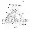
As an example, consider the following topology, with 3 links 1101, 1102 and 1103 that have failed (shown in Red in FIG. 9). Consider a unicast route from N0 to N3. We'll consider the following routing to understand the misrouting technique, understanding that this is only one of several routes that could have been chosen adaptively.
-
- Packet routed N0 to N6.
- Packet routed N6 to N10
- N10 sees that it has no paths to get to N3, other than the link it came in on. N10 sets the misrouting bit in the routing header, and sends it back to N6.
- N6 sees that the packet is being misrouted, sets the bit for the N10 link in the misrouteVector in the routing header, chooses an alternative link that has not been misrouted, and sends the packet to N11.
- N11 sees that it has no path to N3, other than the link it came in on misrouting bit is already on, and sends it back to N6.
- N6 sees that the packet is being misrouted, adds N11 link to the misrouteVector (now contains N10 and N11 link IDs), chooses an alternative link that has not been misrouted, and sends it N7.
- N7 sees that the misrouting bit is set, but does have a valid link to N3 (to N12), and thus clears the misrouting bit in the header, and forwards the packet to N12.
- N12 sends to N9.
- N9 unicastRoute now likely contains link to N3 (weight=3) and link to N8 (weight=2). Normal adaptive routing will not choose the direct link to N3 since it's down, and will route the packet to N8, then finally to N3.
- If N6 had exhausted its list of candidate links (meaning the misrouteVector masked them all), the implementation then has two choices:
- drop the packet and inform the M3 of the failure to route.
- clear the misrouteVector leaving misrouting set, and forward the packet through one of the downward facing links (if one exists). This will retry misrouting at one layer lower. The implementation may want to have a register bit (enableRecursiveMisrouting) to enable this retry at lower layer option.
There is a register enableMisrouting that allows software to control whether the switch will initiate the misrouting algorithm.
Multi-Domaining
Also known to the inventors is Multi-Domaining, whose goal is to increase the addressability of nodes to a large number of nodes (e.g., 64K nodes), without having to increase the size of the unicast routing table to 64K nodes.
As currently described, the unicast routing table is a single-dimension array indexed by node number (i.e. 0 to MAX_NODES−1), where a typical implementation will be between 256 and 4K nodes.
This section will now describe how the current architecture is altered to support multiple domains, with 64K max nodes.
-
- The node namespace is changed from a node ID from 0 to MAX_NODES−1, to a 2-tuple of (domain ID, node ID), where both domain ID and node ID range from 0 to 255. So, there can effectively be 256 domains where each domain can contain up to 256 nodes.
- The unicast routing table is changed from a single dimension table of size MAX_NODES, to a two-dimension table of size 256. The unicast routing table is now changed from a structure of unicastRoute[NODES] to unicastRoute[2][256].
- Local domain routing: When routing to a node within this domain, the unicast routing table is accessed as unicastRoute[0][node ID], and provides a weighted link vector to route to the specified node ID from the current node.
- Remote domain routing: When routing to a node within a remote domain, the unicast routing table is accessed as unicastRoute[1][domain ID], and provides a weighted link vector to route to the specified domain ID from the current node.
- Routing frame: One bit is added to the routing frame, dstRemote, which is set true when routing to a remote domain.
- Locally administered MAC addresses: The section below describes the Node Encoded Unicast MAC address encoding as follows:
| Node | Unicast | 10 bits: |
| Encoded | Locally | SS_MAC_NODE_ENCODED_MAGIC |
| Unicast | administered | 12 bits: Node ID |
| OUI == Switch | 2 bits: Port ID | |
| OUI | ||
This nets altered for multi-domaining as follows.
| Node | Unicast | 6 bits: |
| Encoded | Locally | SS_MAC_NODE_ENCODED_MAGIC |
| Unicast | administered | 8 bits: Domain ID |
| OUI == Switch | 8 bits: Node ID | |
| OUI | 2 bits: Port ID | |
-
- Creating the routing frame header: Table 2 describes the algorithms for creating the routing frame header. This is augmented in the multi-domaining case by:
| if ( dstDomain == myDomainID ) { | // Route to local domain |
| rframe.dstRemote = false; |
| rframe.dstNode = dstNode; |
| } |
| else { | // Route to remote domain |
| rframe.dstRemote = true; |
| rframe.dstNode = dstDomain; |
Network Proxy
The concept of network proxy is the ability of the main processors (FIG. 5A, 905) to maintain network presence while in a low-power sleep/hibernation state, and intelligently wake when further processing is required. There are several architectural features related to Network Proxy:
-
- There is a CSR (portRemap) to allow the remapping of Port IDs. In effect, when the switch is to deliver a packet to an internal MAC0 port (e.g. FIG. 5A, 902), this Port Remapping CSR allows software to remap MAC0 to the management processor MAC (e.g. FIG. 5A, 907) and have the packet delivered to the management processor for Network Proxy processing. This remapping CSR could also be used to remap MAC1 traffic to MAC0, or MAC1 traffic to the management processor.
- Normally, the switch looks at the destination node ID of the routing frame to decide whether the packet is delivered to an internal port within the node, or gets routed to other XAUI connected nodes. This is done by matching Destination Node ID to “My Node ID”. The Node ID Match register (nodeRangeLo, nodeRangeHi) causes the packet to be delivered to an internal port within the node if nodeRangeLo<=Destination_Node<=nodeRangeHi∥myNodeID==Destination_Node. This allows a node to proxy for a subtree of nodes.
A typical use sequence would be of the form: - Management processor maintains the IP to MAC address mappings for MAC0 and MAC1 on the node. This can be done via either explicit communication of these mappings from the main processor OS to the management processor, or can be done implicitly by having the management processor snoop local gratuitous ARP broadcasts.
- The main processor coordinates with the management processor to go to a low power dormant state. During this transition, the management processor sets up the Port ID remapping CSR to route MAC0 and MAC1 traffic to the management processor.
- The management processor processes any incoming MAC0/MAC1 packets. There are 3 categories of processing:
- Respond to some classes of transactions that require simple responses (e.g. ARP responses and ICMP ping).
- Dump and ignore some classes of packets, typically unicast or broadcast packets that are targeting other computers.
- Decide that the main processor must be woken to process some classes of packets. The management processor will wake the main processor, undo the Port ID remapping register, and re-send the packets back through the switch where they will get rerouted back to MAC0/1.
Wake-on-LAN Magic Packet
In a traditional desktop computer, the computer to be woken is shut down (sleeping, hibernating, or soft off; i.e., ACPI state G1 or G2), with power reserved for the network card, but not disconnected from its power source. The network card listens for a specific packet containing its MAC address, called the magic packet, broadcast on the broadcast address for that particular subnet (or an entire LAN, though this requires special hardware or configuration). The magic packet is sent on the data link or layer 2 in the OSI model and broadcast to all NICs within the network of the broadcast address; the IP-address (layer 3 in the OSI model) is not used. When the listening computer receives this packet, the network card checks the packet for the correct information. If the magic packet is valid, the network card takes the computer out of hibernation or standby, or starts it up.
The magic packet is a broadcast frame containing anywhere within its payload: 6 bytes of ones (resulting in hexadecimal FF FF FF FF FF FF), followed by sixteen repetitions of the target computer's MAC address. Since the magic packet is only scanned for the string above, and not actually parsed by a full protocol stack, it may be sent as a broadcast packet of any network- and transport-layer protocol. It is typically sent as a UDP datagram to port 0, 7 or 9, or, in former times, as an IPX packet.
Using the Network Proxy architecture just described, the management processor can support these Wake-On-LAN packets. It will get these broadcast packets, will know the MAC addresses for the other MACs on the node, and be able to wake up the main processor as appropriate. No further functionality is needed in the switch to support these Wake-on-LAN packets.
While the foregoing has been with reference to a particular embodiment of the invention, it will be appreciated by those skilled in the art that changes in this embodiment may be made without departing from the principles and spirit of the disclosure, the scope of which is defined by the appended claims.
Claims
1. A method of fault-resilient unicast routing in a switch fabric having a plurality of nodes and a plurality of links associated with each node that connect the node to another node in the plurality of nodes to create a switch fabric with a plurality of routes, the method comprising:
generating an escape route from a first node to a second node in the switch fabric wherein the escape route has a low priority weight; and
misrouting data from the first node to the second node when a link is inactive wherein the escape route and misrouting provide fault tolerance to the switch fabric.
2. The method of claim 1, wherein the misrouting data from the first node to the second node further comprises iteratively backtracking to route data from the first node to the second node through one or more intervening nodes when a link between the first and second nodes is inactive.
3. The method of claim 2, wherein the iteratively backtracking further comprises:
setting, when a node in the data path does not have a link path to the second node, a misrouting bit in a header of the data;
sending the data back to an originating node that sent the data to the node that set the misrouting bit;
choosing one or more alternate links, by the originating node, for the data; and
clearing the misrouting bit in a header of the data if the data reaches the second node over one of the alterative links.
4. A switch system, comprising:
a plurality of nodes;
a plurality of links associated with each node that connect the node to another node in the plurality of nodes to create a topology of the switch fabric for routing data through the plurality of nodes; and
a management processor that controls the routing of data through the switch fabric, wherein the management process stores a nodenamespace array wherein each nodename has a domain identifier and a node identifier and a two dimensional routing table wherein data packets are routing to a multi-domain node that is identified by the node identifier and the domain identifier.
5. A switch system, comprising:
a plurality of nodes;
a plurality of links associated with each node that connect the node to another node in the plurality of nodes to create a topology of the switch fabric for routing data through the plurality of nodes;
a management processor that controls the routing of data through the switch fabric; and
at least one routing header processor that generates a routing frame header for an Ethernet frame packet using a routing table, the routing table compressing two or more contiguous MAC addresses into a single entry in the routing table.
6. A switch system, comprising:
a plurality of nodes;
a plurality of links associated with each node that connect the node to another node in the plurality of nodes to create a topology of the switch fabric for routing data through the plurality of nodes;
a management processor that controls the routing of data through the switch fabric; and
at least one routing header processor that generates a routing frame header for an Ethernet frame packet using a routing table, the routing table having a link encoded unicast entry in which a particular Ethernet frame packet is communicate over a specific link to a destination node.
7. A switch system, comprising:
a plurality of nodes;
a plurality of links associated with each node that connect the node to another node in the plurality of nodes to create a topology of the switch fabric for routing data through the plurality of nodes;
a management processor that controls the routing of data through the switch fabric; and
at least one routing header processor that generates a routing frame header for an Ethernet frame packet using a routing table, the routing table having a node encoded unicast entry so that an Ethernet frame packet is sent to a node having a particular node ID so that the node ID is encoded into the address.
8. A switch system, comprising:
a plurality of nodes;
a plurality of links associated with each node that connect the node to another node in the plurality of nodes to create a topology of the switch fabric for routing data through the plurality of nodes;
a management processor that controls the routing of data through the switch fabric;
at least one routing header processor that generates a routing frame header for an Ethernet frame packet using a routing table; and
wherein the management processor snoops a locally initiated broadcast and the locally initiated broadcast is sent to the management processor.
9. A switch system, comprising:
a plurality of nodes;
a plurality of links associated with each node that connect the node to another node in the plurality of nodes to create a topology of the switch fabric for routing data through the plurality of nodes;
a management processor that controls the routing of data through the switch fabric; and
at least one routing header processor that generates a routing frame header for an Ethernet frame packet using a routing table, the routing table mapping a non-switch fabric address to a node.
10. A switch system, comprising:
a plurality of nodes;
a plurality of links associated with each node that connect the node to another node in the plurality of nodes to create a topology of the switch fabric for routing data through the plurality of nodes;
a management processor that controls the routing of data through the switch fabric; and
at least one routing header processor that generates a routing frame header for an Ethernet frame packet using a routing table, the routing table having a path cost and weights for each link to permit adaptive routing of the data packets.
Images & Drawings included:


Sources:
- United States Patent and Trademark Office - verify current appl. status at the USPTO↗
Recent applications in this class:
- » 20130343387 2013-12-26
High-speed CLD-based internal packet routing - » 20130322454 2013-12-05
Multipath effectuation within singly contiguous network fabric via switching device routing logic programming - » 20130272304 2013-10-17
Packet switching without look-up table for ethernet switches - » 20130266019 2013-10-10
L3 gateway for VXLAN - » 20130191257 2013-07-25
Connectivity system for multi-tenant access networks - » 20130159549 2013-06-20
Device communications over unnumbered interfaces - » 20130151676 2013-06-13
Logical L3 routing with DHCP - » 20130151661 2013-06-13
Handling NAT migration in logical L3 routing - » 20130114599 2013-05-09
Packet steering - » 20130107880 2013-05-02
Method and apparatus for scalable network transaction identifier for interconnects
Recent applications for this Assignee:
- » 20240265961 2024-08-08
SIGNAL TIMING ALIGNMENT BASED ON A COMMON DATA STROBE IN MEMORY DEVICES CONFIGURED FOR STACKED ARRANGEMENTS - » 20240012581 2024-01-11
Memcached Server Functionality in a Cluster of Data Processing Nodes - » 20230292082 2023-09-14
System and method for generating a recommendation on a mobile device - » 20230131039 2023-04-27
Memcached server functionality in a cluster of data processing nodes - » 20220328091 2022-10-13
Signal timing alignment based on a common data strobe in memory devices configured for stacked arrangements - » 20220295221 2022-09-15
System and method for generating a recommendation on a mobile device - » 20220121545 2022-04-21
System and Method for Continuous Low-Overhead Monitoring of Distributed Applications Running on a Cluster of Data Processing Nodes - » 20220114070 2022-04-14
System, Method and Computer Readable Medium for Offloaded Computation of Distributed Application Protocols within a Cluster of Data Processing Nodes - » 20210134348 2021-05-06
Signal timing alignment based on a common data strobe in memory devices configured for stacked arrangements - » 20210117130 2021-04-22
Memcached server functionality in a cluster of data processing nodes