System for Extracting Heat from Outside Air
US20130062040A1
2013-03-14
13/521,029
2011-01-11
Abstract:
The present invention relates to a system for extracting heat from outside air. The system comprises a feed connecting to outside air, a heat exchanger connected to the feed and a discharge connecting to the heat exchanger and outside air, and a channel connecting the feed, the heat exchanger and the discharge. The system herein further comprises an impeller associated with the channel for providing a volume flow of outside air sufficient for the heat exchanger via the feed and along or through the heat exchanger. The system according the invention is distinguished from existing systems, which make use of noisy fans as impellers, in that the channel comprises an upright ascent pipe, an upright descent pipe and a connecting pipe between the ascent pipe and the descent pipe. The heat exchanger is connected here to the descent pipe. A sufficient airflow can thus be initiated/maintained for an effective operation of for instance the evaporator of or at a heat pump.
Inventors:
- Jan Henk Cnossen 13 🇳🇱 Koudum, Netherlands
- Terence Arthur Devlin 5 🇳🇱 Apeldoorn, Netherlands
Interested in similar patents?
Get notified when new applications in this technology area are published.
Classification:
F24F1/0067 » CPC main
Room units for air-conditioning, e.g. separate or self-contained units or units receiving primary air from a central station; Indoor units, e.g. fan coil units characterised by heat exchangers by the shape of the heat exchangers or of parts thereof, e.g. of their fins
F24D11/0214 » CPC further
Central heating systems using heat accumulated in storage masses using heat pumps water heating system
F24D11/0242 » CPC further
Central heating systems using heat accumulated in storage masses using heat pumps water heating system with recuperation of waste energy contained in exhausted air
F24F5/0096 » CPC further
Air-conditioning systems or apparatus not covered by or , e.g. using solar heat or combined with household units such as an oven or water heater combined with domestic apparatus
F24F12/006 » CPC further
Use of energy recovery systems in air conditioning, ventilation or screening with heat-exchange between supplied and exhausted air using an air-to-air heat exchanger
H01M8/04014 » CPC further
Fuel cells; Manufacture thereof; Auxiliary arrangements, e.g. for control of pressure or for circulation of fluids related to heat exchange Heat exchange using gaseous fluids; Heat exchange by combustion of reactants
H01M8/04201 » CPC further
Fuel cells; Manufacture thereof; Auxiliary arrangements, e.g. for control of pressure or for circulation of fluids; Arrangements for control of reactant parameters, e.g. pressure or concentration Reactant storage and supply, e.g. means for feeding, pipes
H01M8/0656 » CPC further
Fuel cells; Manufacture thereof; Combination of fuel cells with means for production of reactants or for treatment of residues with means for production of gaseous reactants by electrochemical means
F24D2200/02 » CPC further
Heat sources or energy sources Photovoltaic energy
F24D2200/12 » CPC further
Heat sources or energy sources Heat pump
F24D2200/22 » CPC further
Heat sources or energy sources; Waste heat Ventilation air
F24F2007/004 » CPC further
Ventilation Natural ventilation using convection
F24H2240/09 » CPC further
Fluid heaters having electrical generators with photovoltaic cells
F24H2240/10 » CPC further
Fluid heaters having electrical generators with fuel cells
Y02B10/70 » CPC further
Integration of renewable energy sources in buildings Hybrid systems, e.g. uninterruptible or back-up power supplies integrating renewable energies
Y02B10/70 » CPC further
Integration of renewable energy sources in buildings Hybrid systems, e.g. uninterruptible or back-up power supplies integrating renewable energies
Y02B30/52 » CPC further
Energy efficient heating, ventilation or air conditioning [HVAC] Heat recovery pumps, i.e. heat pump based systems or units able to transfer the thermal energy from one area of the premises or part of the facilities to a different one, improving the overall efficiency
Y02B30/52 » CPC further
Energy efficient heating, ventilation or air conditioning [HVAC] Heat recovery pumps, i.e. heat pump based systems or units able to transfer the thermal energy from one area of the premises or part of the facilities to a different one, improving the overall efficiency
Y02B30/56 » CPC further
Energy efficient heating, ventilation or air conditioning [HVAC] Heat recovery units
Y02B30/56 » CPC further
Energy efficient heating, ventilation or air conditioning [HVAC] Heat recovery units
Y02E60/50 » CPC further
Enabling technologies; Technologies with a potential or indirect contribution to GHG emissions mitigation; Hydrogen technology Fuel cells
Y02E60/50 » CPC further
Enabling technologies; Technologies with a potential or indirect contribution to GHG emissions mitigation; Hydrogen technology Fuel cells
F28F13/12 IPC
Arrangements for modifying heat-transfer, e.g. increasing, decreasing by affecting the pattern of flow of the heat-exchange media by creating turbulence, e.g. by stirring, by increasing the force of circulation
Description
The present invention relates to a system for extracting or obtaining heat from outside air, for instance with or in the form of a heat pump. The system is of the type defined in the preamble of the single independent claim. The subject of the present invention is a system which enables for instance heat pumps—operating with (outside) air as heat (or cold) source—to provide the thermal energy required for converting heat (or cold). Such heat pumps extract heat (or cold) from (preferably) outside air and converts it to heat (or cold) which can be used by the user to heat (or cool) spaces and/or hot tap water.
Such systems are generally known and have the shared drawback that sufficient outside air must always be force pumped through a heat exchanger (usually an evaporator) in order to enable collection of the heat required for the heat generating process for this evaporator part of the heat pump. A fan which causes noise nuisance is applied for this purpose.
An arrangement of such a known evaporator with fan is for this reason often placed outside a building or space. The placing of such a system outside a building or space almost always has an adverse effect on the aesthetics, or more generally the appearance, of this building or this space. Furthermore, even though the noise nuisance is then moved outside the building or the space, it can thus still cause annoyance in the vicinity.
From FR-2.726.636 a radiator is known, which exhibits some features of the appended independent claim, to heat inside air.
The invention has for its object to be able to avoid a conventionally required, heavy fan causing noise nuisance for the purpose of air displacement. It is not precluded that a small, quieter fan can be applied if desired. For this purpose the invention is distinguished from the known systems by the assembly of features as defined in combination in the appended independent claim.
The necessary air feed through the channel can thus be provided wholly or at least to a considerable extent on the basis of the operation of the heat exchanger when it is placed in the descent pipe; cold air does after all tend to sink and so pushes the airflow downward through the descent pipe. Applying a large, heavy fan causing noise nuisance can hereby be avoided. The channel of the system can be placed inside the building or even form an integral part thereof, or be arranged outside along the outer wall, without generating disturbing noise or raising aesthetic objections. The channel can extend over different floors of a building or be limited in vertical length to the height available in a technical area. A suitable mean can be chosen here between the effectiveness and the efficiency of the system relative to the aesthetic impact of arranging or providing such a channel, and whether this channel can therefore be arranged outside the outer wall. The channel can extend partly inside and partly outside the building or the space.
In addition or as alternative to these kinds of possibility within the scope of the invention as according to the definition thereof in the single independent claim, the dependent claims relate to further preferred embodiments.
A system according to the invention can thus further have the feature that a heater is provided which is substantially associated with the ascent pipe. The effectiveness can thus be increased in order to enhance still further the throughfeed of air in the channel. Warm air does after all tend to rise and so pushes the airflow upward through the ascent pipe.
A system with a heater according to the invention can thus have the further feature that the ascent pipe and the descent pipe both extend substantially upward from the connecting pipe, and the heater is substantially associated with at least one of the ascent pipe and the connecting pipe. In another embodiment, with or without a heater, a system according to the invention can have the feature that the ascent pipe and the descent pipe both extend substantially downward from the connecting pipe, and the heat exchanger is substantially associated with at least one of the descent pipe and the connecting pipe. In such embodiments either the heat exchanger or the heater (if present) can already begin in the connecting pipe to act on the airflow, which then flows further to the other of the descent pipe and the ascent pipe. The connecting pipe can thus be deemed a turning point in the flow direction of the airflow through the descent pipe and the ascent pipe, and at least the heat exchanger and also—if present—the heater can already begin to have an effect on the flow at or in this turning point in order to increase it.
In another embodiment, with or without a heater, a system according to the invention can have the feature that a heat pump is connected to the heat exchanger. A low-noise or even noise-free thermal supply can thus be realized for the heat pump to thereby in order to enable effecting of the function thereof.
In another embodiment, with or without a heater, a system according to the invention can have the feature that a storage tank is associated with the heat exchanger and the heat pump. A buffer supply can thus be established, for instance to supply a central heating system or a floor heating therewith when the system according to the invention is temporarily not functioning or functioning less well.
In another embodiment with a heater a system according to the invention can have the feature that the heater is associated with at least a considerable part of a length of the ascent pipe. The temperature of the airflow can thus be increased over the whole length of the ascent pipe in order to thereby also increase the speed at which the airflow rises through the ascent pipe and further increase the efficiency of the system. It is preferably possible here for the heater to be associated with substantially the whole length of the ascent pipe. Optimization of the increase in the flow speed of the airflow through the ascent pipe can thus be realized, provided this is warranted on the basis of energy considerations in the light of the power consumed by the heater and the origin thereof.
In another embodiment, with or without a heater, a system according to the invention can have the feature that the heat exchanger is associated with at least a considerable part of a length of the descent pipe. Similar considerations as above for the heater at the ascent pipe also apply here in respect of increasing the speed at which the airflow descends through the descent pipe. It can then also be recommended for the heat exchanger to be associated with substantially the whole length of the descent pipe in order to optimize the speed.
In another embodiment, with or without a heater, a system according to the invention can have the feature that the heater is at least one of the elements or components from the group comprising: fuel cells, electric heating elements and so on. Such emission-free heaters are recommended.
With a heater in the form of a fuel cell it can be recommended here for a gas container to be provided for containing a buffer supply of gas required by the fuel cell. Continuous functioning can thus be ensured, even if gas supply is (temporarily) interrupted.
Additionally or alternatively the system can then further comprise an electrolysis unit for providing the fuel cell with hydrogen and/or oxygen gas required thereby. The requirements of the fuel cell can thus be provided locally.
In another embodiment, with or without a heater, a system according to the invention can have the feature of a solar collector for generating electric power required by the system from solar energy. This power can be utilized for (a selection of) components of the system or associated elements/components such as the heat pump, the heater, the electrolysis unit etc.
In another embodiment, with or without a heater, a system according to the invention can have the feature of a heat exchanger connected to the feed and the discharge for recovering heat from discharge air. It is thus made possible to recover heat from the airflow leaving the system at the discharge and so further increase the efficiency of the system.
An embodiment of the present invention will be described hereinbelow by way of example and not by way of limitation, with reference to the accompanying figures, in which the same or similar parts, components and aspects are designated with the same reference numerals, and in which:
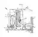
FIG. 1A shows a schematic overview of a system according to the invention;
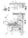
FIG. 1B shows an alternative for a part of the system in FIG. 1A; and
FIG. 1C shows an alternative for a different part of the system in FIG. 1A than in FIG. 1B.
The idea for this invention relates to a system 1 which makes it possible for heat pumps 2—operating with air, preferably outside air, as heat (or cold) source—to produce the thermal energy required to convert heat (or cold) in extremely quiet manner, i.e. without heavy, noisy fans.
This type of heat pump 2 extracts heat (or cold) from (preferably) outside air via a feed 3 and converts it to heat (or cold) which can be used by the user to heat (or cool) spaces via feed conduit 5 and return conduit 6 and/or of hot tap water.
A problem in this type of heat pump 2 is that there must always be a forced flow of sufficient outside air through a heat exchanger (evaporator) 7 to enable collection of the heat required for the heat-generating process for heat exchanger 7 of heat pump 2.
A fan has usually been used for this purpose in the past and this causes noise nuisance.
With the intended invention a fan for air displacement is unnecessary (a small, quieter fan can however be applied if desired).
The system according to the invention in the embodiment shown in FIG. 1 comprises an ascent pipe 8, a connecting pipe 9 and a descent pipe 10, which together form a channel. Ascent pipe 8 and descent pipe 10 extend in vertical direction over the greatest possible height (usually limited by the height available in a (technical) area in which the system is arranged). The system can also be arranged in, against or outside an outer wall of a building and so not be limited in height to the space available in a technical area.
In descent pipe 10, which forms a cooling part of the channel, air is cooled by the heat exchanger 7 of heat pump 2 mounted in, on or round this pipe in order to form an evaporator part thereof. An air circulation (airflow in downward direction) through descent pipe 8 is hereby initiated. Heat exchanger 7 of heat pump 2 can extend over the whole length of descent pipe 8 of the channel.
When the channel is mounted for aesthetic reasons in a building or space, feed 3 and discharge 4 are situated in outer wall 11, preferably placed close together in the same outer wall surface, so that differences in air pressure caused for instance by wind are minimized.
In the same manner as at or in descent pipe 8, the air circulation process in ascent pipe 10 of the channel can also be additionally stimulated by heating air using a heater 12—placed for this purpose in sequence before the cooling part.
The open outer ends of the channel, which takes the form of a U-shaped pipe, form feed 3 and discharge 4, and are directly connected to the outside air.
A heater 12 in ascent pipe 8 of the channel can be formed by or consist of a fuel cell 12. The heat released during the reaction between oxygen and hydrogen is here relinquished directly into the air channel.
Instead of a fuel cell 13 it is also possible to use other heaters, such as an electric heating element 16 as shown in FIG. 1B. Any random heater for generating heat is in fact suitable for this purpose, although it is noted that embodiments which contribute toward a low emission are recommended.
It is also possible to arrange more than one heater 12 (of the same or different types) in the ascent pipe of the channel. The whole length of the ascent part of the channel can also be utilized here for the arrangement of heaters 12.
Heating the air in ascent pipe 8 of the channel causes the airflow to rise. New, cooler outside air is hereby drawn in from outside via feed 3.
It can be said that there is an airflow in the channel because, beyond the highest point formed by connecting pipe 9, an opposite effect caused by heat exchanger 7 associated with heat pump 2 takes place in descent pipe 10 of the channel.
Heat exchanger 7 in the form of an evaporator for heat pump 2 is arranged in descent pipe 10 of the channel. The heat previously heated in ascent pipe 8 is cooled in descent pipe 10 to a temperature lower than that of the outside air.
Fuel cell 13 shown in FIG. 1A is provided with hydrogen or oxygen by an electrolysis unit 14. An aqueous conductive solution (salt or acid) is present in this electrolysis unit 14. The electricity required for the electrolysis preferably comes from a photovoltaic (PV) solar panel 15. It is possible to establish a gas supply, whereby solar cell 13 can be supplied at times when no sunlight is available. A buffer tank (not shown) can be utilized for this purpose.
There can also be a direct power supply from a PV solar panel 15 to electric heater 16 in FIG. 1B in, on or at ascent pipe 8 of the channel. The electricity generated by solar panel 15 is available to heat pump 2 or other parts of the system, but can also be delivered to the GRID (public supply network).
In another embodiment the outside air can first also be heated in a heat exchanger as is applied in a heat-recovery system for ventilation air. This embodiment is shown in FIG. 1C.
After examination of the foregoing description of a possible embodiment with reference to the accompanying figures, to which the invention is by no means limited, many alternative and additional embodiments will occur to the skilled person, which must all be deemed as embodiments of the invention to the extent these variants comply with the definitions in the claims, either literally or in that the same objectives are sought after therein with the same or similar means. The figures thus do not show that the channel can also be embodied in a reverse position. Feed 3 and discharge 4 of the channel are then situated for instance in a construction of a roof of a building, here also preferably placed close together in the same roof surface so that differences in air pressure caused for instance by wind are minimized. The ascent pipe and the descent pipe of the channel are then in reverse order:
-
- in descent pipe 10 of the channel the outside air is cooled by heat exchanger 7 of heat pump 2, whereby the airflow is set into motion in downward direction through descent pipe 10 to connecting pipe 9, and
- the previously cooled air is heated in ascent pipe 8 of the channel by an above described fuel cell 13 and/or electric heating element 16 or the like, whereby the airflow in upward direction through ascent pipe 8 is stimulated.
The channel of the system according to the invention can be incorporated in an outer wall in order to realize a greater height thereof than is available in a technical area. This can of course be taken into account during the design and construction of a building, or can be realized during renovation of at least the outer wall of an existing building.
Claims
1. A system for extracting heat from outside air, the system comprising:
a feed connecting to outside air;
a heat exchanger connected to the feed;
a discharge connecting to the heat exchanger and outside air;
a channel connecting the feed, the heat exchanger and the discharge;
an impeller associated with the channel for providing a volume flow of outside air sufficient for the heat exchanger via the feed and along or through the heat exchanger wherein:
the channel comprises an upright ascent pipe, an upright descent pipe and a connecting pipe between the ascent pipe and the descent pipe; and
the heat exchanger is associated with the descent pipe.
2. The system as claimed in claim 1, wherein a heater is provided which is substantially associated with the ascent pipe.
3. The system as claimed in claim 1, wherein the ascent pipe and the descent pipe both extend substantially upward from the connecting pipe, and the heater is substantially associated with at least one of the ascent pipe and the connecting pipe.
4. The system as claimed in claim 1, wherein the ascent pipe and the descent pipe both extend substantially downward from the connecting pipe, and the heat exchanger is substantially associated with at least one of the descent pipe and the connecting pipe.
5. The system as claimed in claim 1, wherein a heat pump is connected to the heat exchanger.
6. The system as claimed in claim 5, wherein a storage tank is associated with the heat exchanger and the heat pump.
7. The system as claimed in claim 2, wherein the heater is associated with at least a considerable part of a length of the ascent pipe.
8. The system as claimed in claim 7, wherein the heater is associated with substantially the whole length of the ascent pipe.
9. The system as claimed in claim 1, wherein the heat exchanger is associated with at least a considerable part of a length of the descent pipe.
10. The system as claimed in claim 9, wherein the heat exchanger is associated with substantially the whole length of the descent pipe.
11. The system as claimed in claim 2, wherein the heater is at least one of the elements or components from the group comprising: fuel cells, electric heating elements or any other heater.
12. The system as claimed in claim 11, with a heater in the form of a fuel cell, wherein a gas container is provided for containing a buffer supply of gas required by the fuel cell.
13. The system as claimed in claim 11, further comprising an electrolysis unit for providing the fuel cell with hydrogen and/or oxygen gas required thereby.
14. The system as claimed in claim 1, further comprising a solar collector for generating electric power required by the system from solar energy.
15. The system as claimed in claim 1, further comprising a heat exchanger connected to the feed and the discharge for recovering heat from discharge air.
Images & Drawings included:
Sources:
- United States Patent and Trademark Office - verify current appl. status at the USPTO↗
Recent applications in this class:
- » 20240240802 2024-07-18
INDOOR UNIT AND AIR CONDITIONER - » 20240044525 2024-02-08
Reticular resin molding and operating method of air conditioner using same - » 20240044524 2024-02-08
Air conditioner units and heating elements thereof - » 20240011648 2024-01-11
MICROCHANNEL HEAT EXCHANGER FOR HEAT PUMP - » 20230383962 2023-11-30
Heat Exchanger, Electric Control Box and Air Conditioning System - » 20230358419 2023-11-09
AIR HANDLER - » 20230341135 2023-10-26
Heat exchanger for a heating, ventilation, and air-conditioning system - » 20230332776 2023-10-19
INDOOR HEAT EXCHANGER AND INDOOR UNIT OF AIR-CONDITIONING APPARATUS - » 20220404039 2022-12-22
Heat exchanger fin, heat exchanger, indoor unit and air conditioner - » 20220316717 2022-10-06
Devices and methods of optimizing refrigerant flow in a heat exchanger