WIND TURBINE ROTOR BLADE
US20130064675A1
2013-03-14
13/583,622
2011-03-09
Abstract:
The invention concerns a wind power installation rotor blade. The rotor blade has a rotor blade root, a rotor blade tip, a rotor blade leading edge and a rotor blade trailing edge. The rotor blade further has a pressure side and a suction side as well as at least one web at least partially between the suction and pressure sides. The rotor blade has a longitudinal direction between the rotor blade root and the rotor blade tip. The web is of a wave-shaped configuration in the longitudinal direction of the rotor blade.
Assignee:
- WOBBEN PROPERTIES GMBH 448 🇩🇪 Aurich, Germany
Interested in similar patents?
Get notified when new applications in this technology area are published.
Classification:
F03D1/0675 » CPC main
Wind motors with rotation axis substantially parallel to the air flow entering the rotor ; Rotors characterised by their construction, i.e. structural design details of the blades
B29C51/00 » CPC further
Shaping by thermoforming, i.e. shaping sheets or sheet like preforms after heating , e.g. shaping sheets in matched moulds or by deep-drawing; Apparatus therefor
B29K2105/12 » CPC further
Condition, form or state of moulded material or of the material to be shaped containing reinforcements, fillers or inserts of short lengths, e.g. chopped filaments, staple fibres or bristles
B29L2031/08 » CPC further
Other particular articles Blades for rotors, stators, fans, turbines or the like, e.g. screw propellers
F05B2240/30 » CPC further
Components; Rotors Characteristics of rotor blades, i.e. of any element transforming dynamic fluid energy to or from rotational energy and being attached to a rotor
F05B2250/184 » CPC further
Geometry two-dimensional patterned sinusoidal
F05B2250/611 » CPC further
Geometry; Structure; Surface texture corrugated undulated
Y02E10/72 » CPC further
Energy generation through renewable energy sources; Wind energy Wind turbines with rotation axis in wind direction
Y02E10/72 » CPC further
Energy generation through renewable energy sources; Wind energy Wind turbines with rotation axis in wind direction
Y10T29/49337 » CPC further
Metal working; Method of mechanical manufacture; Impeller making; Blade making Composite blade
F03D1/06 IPC
Wind motors with rotation axis substantially parallel to the air flow entering the rotor Rotors
B32B1/04 IPC
Layered products having a general shape other than plane characterised by feature of form at particular places, e.g. in edge regions
B23P15/04 IPC
Making specific metal objects by operations not covered by a single other subclass or a group in this subclass turbine or like blades from several pieces
Description
BACKGROUND
1. Technical Field
The present invention concerns a wind power installation rotor blade.
2. Description of the Related Art
DE 103 36 461 describes a wind power installation rotor blade, wherein spars of composite fiber materials are provided in a rotor blade in the longitudinal direction. Those spars can be made for example from glass fiber-reinforced fibers, for example by impregnation in a resin. The spars are typically provided both at the suction side of the rotor blade and also at the pressure side. The spares can be produced beforehand and then fitted into the rotor blades or half-shell portions. That has the advantage that the spars can be produced beforehand under constant conditions. In particular that is intended to avoid the spars becoming wavy during production. Waviness of the spars is unwanted because the spars serve to carry loads. Thus it is necessary to provide quality assurance to prevent the spars becoming wavy or undulating.
The general state of the art attention is shown in DE 10 2008 022 548 A1 and DE 203 20 714 U1.
BRIEF SUMMARY
One object of the present invention is to provide a wind power installation rotor blade which permits inexpensive manufacture.
That object is attained by a wind power installation rotor blade according to claim 1.
Thus there is provided a wind power installation rotor blade. The rotor blade has a rotor blade root, a rotor blade tip, a rotor blade leading edge and a rotor blade trailing edge. The rotor blade further has a pressure side and a suction side as well as at least one web at least partially between the suction and pressure sides. The rotor blade has a longitudinal direction between the rotor blade root and the rotor blade tip. The web is of a wave-shaped configuration in the longitudinal direction of the rotor blade.
In an aspect of the present invention the rotor blade has spars at the pressure side and at the suction side. The at least one web is fixed in the region of the spars.
In a further aspect of the present invention the web is produced by hot shaping of fiber-reinforced thermoplastic materials.
In a further aspect of the present invention the wave shape of the web is of a sinusoidal configuration.
In a further aspect of the present invention there are provided at least two substantially mutually parallel webs.
The invention also concerns a use of webs of a wave-shaped configuration in the production of a wind power installation rotor blade.
The invention also concerns a wind power installation having at least one rotor blade as described hereinbefore.
The invention is based on the concept of providing a wind power installation rotor blade having webs between the pressure side and the suction side of the rotor blade. The webs are not straight in longitudinal section, but are of a wave-shaped or undulating configuration.
Thus there is provided a wavy or undulating or a sinusoidally wavy web or spar web. The spar web can be produced for example from fiber-reinforced thermoplastic materials so that an automatic production line can be implemented for example by hot shaping of the fiber-reinforced thermoplastic materials. Preferably the fiber-reinforced thermoplastic materials are unwound from a roll.
Preferably the webs are produced by machine from thermoplastic material. As an alternative thereto the webs can be produced from pre-preps with subsequent UV hardening.
The webs serve to increase the strength of the rotor blade. For that purpose the webs can be provided between the suction and pressure sides of the rotor blade. The webs can be fixed or glued for example to the spars provided along the pressure side and the suction side. Those webs serve only for providing strength, but not for carrying away the load within the rotor blade.
Further configurations of the invention are subject-matter of the appendant claims.
BRIEF DESCRIPTION OF THE SEVERAL VIEWS OF THE DRAWING(S)
Advantages and embodiments by way of example of the invention are described in greater detail hereinafter with reference to the drawing.
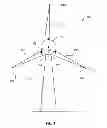
FIG. 1 shows a diagrammatic view of a wind power installation according to the invention,
FIG. 2 shows a cross-section of a wind power installation rotor blade for the wind power installation of FIG. 1, and
FIG. 3 shows a longitudinal section of a wind power installation rotor blade for the wind power installation of FIG. 1
DETAILED DESCRIPTION
FIG. 1 shows a diagrammatic view of a wind power installation according to the invention. The wind power installation 100 has a pylon 110 with a pod 120 at the upper end of the pylon 110. For example three rotor blades 130 are arranged on the pod 120. The rotor blades 130 have a rotor blade tip 132 and a rotor blade root 131. The rotor blades 130 are fixed at the rotor blade root 131 for example to the rotor hub 121. The pitch angle of the rotor blades 130 is preferably controllable in accordance with the currently prevailing wind speed.
FIG. 2 shows a cross-section of a wind power installation rotor blade according to a first embodiment. As shown in FIG. 1 the rotor blade 130 has rotor blade tip 132 and a rotor blade root 131. The rotor blade 130 also has a leading edge 133 and a trailing edge 134. Furthermore the rotor blade 130 has a suction side 135 and a pressure side 136. Webs 200 can be provided between the pressure and the suction sides 136, 135 at least partially along the length of the rotor blade (between the rotor blade root and rotor blade tip 131, 132). The webs have a first end that connects to a first spar 201 and a second end that connects to a different spar 202. The first spar 201 is fixed to the suction side 135 and the second spar 202 is fixed to the pressure side 136. In other words the webs are mechanically connected to the suction side and the pressure side. The webs 200 are preferably provided to improve the mechanical stability of the rotor blades. The webs can be provided continuously or at least partially along the length or the longitudinal direction of the rotor blade between the rotor blade root 131 and the rotor blade tip 132.
In the first embodiment the webs 200 are of an undulating configuration, a wave-shaped configuration or a sinusoidal configuration, along the longitudinal direction. Alternatively thereto the webs 200 can also be in the form of a sawtooth or a triangular undulation along the longitudinal direction.
The webs can serve to transmit a part of the lift force from the pressure side to the suction side. The webs can thus transmit forces perpendicularly to their longitudinal direction, that is to say from the pressure side of the rotor blade to the suction side. The webs however are less suited to transmitting forces in the longitudinal direction thereof.
FIG. 3 shows a longitudinal section of a wind power installation rotor blade for the wind power installation of FIG. 1. The rotor blade has a rotor blade root 131, a rotor blade tip 132, a rotor blade leading edge 133 and a rotor blade trailing edge 134. In addition webs 200 extend between the pressure side and the suction side of the rotor blade (as shown in FIG. 2). Those webs 200 are of a wave-shape, undulating or sinusoidal configuration along the longitudinal direction of the rotor blade. Alternatively thereto the webs 200 can also be in the form of a sawtooth or a triangular undulation.
The webs shown in FIGS. 2 and 3 can be made by machine for example from a thermoplastic material. That can be effected for example by hot shaping of fiber-reinforced thermoplastic materials.
The webs can be produced in particular from rolled-up fiber-reinforced thermoplastic materials, in which case the wave shape can be produced by the hot shaping operation.
A saving in material of between 10% and 20% (in particular 15%) can be achieved by those webs of a wave-shaped configuration. As the webs are of a wave-shaped or undulating configuration in the longitudinal direction they do not contribute to carrying load so that the load is still carried away as previously by way of fiber-reinforced spars provided at the pressure and suction sides. On the other hand a lift force caused by the wind can be transmitted for example in a proportion of 90% by way of the webs 200.
The various embodiments described above can be combined to provide further embodiments. All of the U.S. patents, U.S. patent application publications, U.S. patent application, foreign patents, foreign patent application and non-patent publications referred to in this specification and/or listed in the Application Data Sheet are incorporated herein by reference, in their entirety. Aspects of the embodiments can be modified, if necessary to employ concepts of the various patents, application and publications to provide yet further embodiments.
These and other changes can be made to the embodiments in light of the above-detailed description. In general, in the following claims, the terms used should not be construed to limit the claims to the specific embodiments disclosed in the specification and the claims, but should be construed to include all possible embodiments along with the full scope of equivalents to which such claims are entitled. Accordingly, the claims are not limited by the disclosure.
Claims
1. A wind power installation rotor blade comprising
a rotor blade root, a rotor blade tip, a rotor blade leading edge and a rotor blade trailing edge,
a pressure side and a suction side, and
at least one web at least partially between the suction and pressure sides, the web having a wave-shaped configuration of the web in a longitudinal direction of the rotor blade,
wherein the longitudinal direction of the rotor blade extends between the rotor blade root and the rotor blade tip,
2. The rotor blade according to claim 1 further comprising spars at the pressure side and/or the suction side, wherein the at least one web is fixed in the region of the spars.
3. The rotor blade according to claim 1 characterized by a web produced by hot shaping of fiber-reinforced thermoplastic materials.
4. The rotor blade according to claim 1 characterized by a sinusoidal configuration for the wave shape of the web.
5. The rotor blade according to claim 1 characterized by at least two substantially mutually parallel webs.
6. The rotor according to claim 1, comprising use of webs of a wave-shaped configuration in the production of a wind power installation rotor blade.
7. A wind power installation having at least one rotor blade according to claim 1.
8. A process for the production of a wind power installation rotor blade which has a rotor blade root, a rotor blade tip, a rotor blade leading edge, a rotor blade trailing edge, a pressure side and a suction side, comprising:
providing a web of a wave-shaped configuration in the longitudinal direction of the rotor blade.
9. The process according to claim 8 wherein the at least one web is produced by hot shaping of fiber-reinforced thermoplastic materials.
10. A wind power installation rotor blade comprising:
a first side;
a second side; and
at least one web between the first side and the second side, the web having an undulating configuration at least partially along a longitudinal direction of the rotor blade from a rotor blade root to a rotor blade tip.
11. The rotor blade according to claim 10,
wherein the undulating configuration is a wave-shaped configuration.
12. The rotor blade according to claim 10,
wherein the undulating configuration is a sinusoidal configuration.
13. The rotor blade according to claim 10,
wherein the undulating configuration is a sawtooth configuration.
14. The rotor blade according to claim 10,
wherein the undulating configuration is a triangular undulation configuration.
15. The rotor blade according to claim 10, further comprising:
a spar at the first side; and
the at least one web is fixed to the spar.
16. The rotor blade according to claim 10, further comprising:
a spar at the second side; and
the at least one web is fixed to the spar.
17. The rotor blade according to claim 10,
wherein the at least one web is produced by hot shaping of fiber-reinforced thermoplastic materials.
18. The rotor blade according to claim 10,
wherein the at least one web is at least two substantially mutually parallel webs.
Images & Drawings included:


Sources:
- United States Patent and Trademark Office - verify current appl. status at the USPTO↗
Similar patent applications:
- » 20150354541
ROOT BUSHING FOR A WIND TURBINE ROTOR BLADE, A WIND TURBINE ROTOR BLADE, A WIND TURBINE AND A METHOD FOR MANUFACTURING A WIND TURBINE ROTOR BLADE FOR A WIND TURBINE - » 20170152834
Wind-turbine rotor blade, trailing edge for wind-turbine rotor blade tip, method for producing a wind-turbine rotor blade, and wind turbine - » 20150354540
ROOT BUSHING FOR A BLADE ROOT OF A WIND TURBINE ROTOR BLADE, A BLADE ROOT, A WIND TURBINE ROTOR BLADE, A WIND TURBINE AND A METHOD FOR MANUFACTURING A ROOT BUSHING - » 20190316564
Bushing for a wind turbine rotor blade, flange insert, wind turbine rotor blade and wind turbine - » 20150354542
Root bushing for a blade root of a wind turbine rotor blade, a blade root, a wind turbine rotor blade and a wind turbine - » 20150354531
ROOT BUSHING FOR A BLADE ROOT OF A WIND TURBINE ROTOR BLADE, A BLADE ROOT, A WIND TURBINE ROTOR BLADE AND A WIND TURBINE - » 20160138561
Method for mounting a wind turbine rotor blade, and wind turbine rotor blade - » 20180180032
Method for making an equipotential bonding connection on a wind turbine rotor blade and wind turbine rotor blade having an equipotential bonding connection - » 20110274553
Method for Manufacturing a Wind Turbine Rotor Blade and Wind Turbine Rotor Blade - » 20180186040
Method for producing a wind turbine rotor blade, and wind turbine rotor blade
Recent applications in this class:
- » 20250154929 2025-05-15
EXTRUDED THERMOPLASTIC FOAMS AND USES IN APPLICATIONS REQUIRING STRENGTH AND LIGHTWEIGHT - » 20250154928 2025-05-15
ROOT SECTION, WIND TURBINE BLADE AND METHODS FOR PRODUCING AND MODIFYING A ROOT PORTION OF A WIND TURBINE BLADE - » 20250146469 2025-05-08
Apparatus and Method for Repurposed Wind Turbine Blades - » 20250067243 2025-02-27
WIND TURBINE BLADE AND METHOD FOR MANUFACTURING A WIND TURBINE BLADE - » 20250059944 2025-02-20
FAMILY OF AIRFOILS FOR FLUID TURBINE WITH PASSIVE-PITCHING ROTOR BLADES - » 20250052226 2025-02-13
METHOD OF MANUFACTURING AN ADAPTABLE CARBON-FIBER BEAM - » 20250020099 2025-01-16
TIP SYSTEM FOR A WIND TURBINE BLADE - » 20250012249 2025-01-09
WIND TURBINE COMPONENT, WIND TURBINE, AND METHOD FOR MANUFACTURING OF A WIND TURBINE COMPONENT - » 20240401560 2024-12-05
Improved hybrid pultrusion plates for a conductive spar cap of a wind turbine blade - » 20240401559 2024-12-05
Fairing System for a Vertical Axis Wind Turbine
Recent applications for this Assignee:
- » 20250151169 2025-05-08
METHOD AND DEVICE FOR OPERATING A WIND TURBINE GENERATOR IN A HEATING PLANT - » 20250088129 2025-03-13
METHOD FOR CONTROLLING AN ELECTRICAL GENERATOR OF A WIND TURBINE - » 20250027477 2025-01-23
Method for Optimizing a Wind Power Installation - » 20240097537 2024-03-21
Segmented generator, generator segment and wind turbine, and also method for preparing transportation of a segmented generator, and for transporting and installing the same, and also method for assembling a wind turbine - » 20240026857 2024-01-25
Method for operating a wind turbine, wind turbine, and wind park - » 20240018941 2024-01-18
Wind turbine rotor blade and wind turbine - » 20240003336 2024-01-04
Method for de-icing at least one rotor blade of a wind power installation - » 20230417223 2023-12-28
Method for controlling a wind power installation so as to protect birds and bats - » 20230358211 2023-11-09
Method for detecting a sensor malfunction of a load sensor of a wind power installation - » 20230296084 2023-09-21
Method for identifying a blade malposition of a rotor blade of a wind power installation