Device for driving an auxiliary unit
US20130071233A1
2013-03-21
13/675,595
2012-11-13
✅ Patent granted
US 9,273,564 B2
2016-03-01
-
-
Daniel Wiley
Crowell & Moring LLP
2032-11-13
Abstract:
A device for driving an auxiliary unit, in particular a high-pressure pump, includes a rotatably supported drive shaft of an internal combustion engine, wherein the drive shaft and a unit shaft of the auxiliary unit are operatively connected to each other by a coupling. The unit shaft has a first bearing on the side facing away from the coupling, and the coupling is a second bearing for the unit shaft. The device provides a low-cost, acoustically inconspicuous, tolerance-insensitive coupling solution for connecting, for example, a high-pressure pump camshaft to an available intake or exhaust camshaft.
Inventors:
- Bayerische Motoren Werke Aktiengesellschaft 40 🇩🇪 Muenchen, Germany
- Peter FREHLAND 2 🇩🇪 Muenchen, Germany
- Peter Frehland 2 🇩🇪 Munich, Germany
Assignee:
- BAYERISCHE MOTOREN WERKE AKTIENGESELLSCHAFT 3,338 🇩🇪 Munich, Germany
Applicant:
Interested in similar patents?
Get notified when new applications in this technology area are published.
Classification:
F01D15/00 » CPC further
Adaptations of machines or engines for special use; Combinations of engines with devices driven thereby
F01D15/08 » CPC main
Adaptations of machines or engines for special use; Combinations of engines with devices driven thereby Adaptations for driving, or combinations with, pumps
F02B67/04 » CPC further
Engines characterised by the arrangement of auxiliary apparatus not being otherwise provided for, e.g. the apparatus having different functions; Driving auxiliary apparatus from engines, not otherwise provided for of mechanically-driven auxiliary apparatus
F01L1/047 » CPC further
Valve-gear or valve arrangements, e.g. lift-valve gear; Valve drive by means of cams, camshafts, cam discs, eccentrics or the like Camshafts
F16D1/101 » CPC further
Couplings for rigidly connecting two coaxial shafts or other movable machine elements; Quick-acting couplings in which the parts are connected by simply bringing them together axially without axial retaining means rotating with the coupling
F16D2001/102 » CPC further
Couplings for rigidly connecting two coaxial shafts or other movable machine elements; Quick-acting couplings in which the parts are connected by simply bringing them together axially the torque is transmitted via polygon shaped connections
F16D2001/103 » CPC further
Couplings for rigidly connecting two coaxial shafts or other movable machine elements; Quick-acting couplings in which the parts are connected by simply bringing them together axially the torque is transmitted via splined connections
F16D1/10 IPC
Couplings for rigidly connecting two coaxial shafts or other movable machine elements Quick-acting couplings in which the parts are connected by simply bringing them together axially
F16D3/06 » CPC further
Yielding couplings, i.e. with means permitting movement between the connected parts during the drive adapted to specific functions specially adapted to allow axial displacement
Description
CROSS REFERENCE TO RELATED APPLICATIONS
This application is a continuation of PCT International Application No. PCT/EP2011/001746, filed Apr. 8, 2011, which claims priority under 35 U.S.C. §119 from German Patent Application No. 10 2010 020 578.8, filed May 14, 2010, the entire disclosures of which are herein expressly incorporated by reference.
BACKGROUND AND SUMMARY OF THE INVENTION
The invention relates to a device for driving an auxiliary unit, particularly a high-pressure pump wherein a rotatably disposed drive shaft of an internal-combustion engine and a unit shaft of the auxiliary unit are in a mutually operative position by way of a coupling.
Concerning the technical background, reference is made, for example, to German Published Patent Application DE 10 2007 029 651 A1, from which a high-pressure fuel pump arrangement having a pump housing is known for operating a self-igniting internal-combustion engine. This high-pressure fuel pump arrangement has a low-pressure and a high-pressure circulation system and a valve camshaft disposed in a cylinder head of the internal-combustion engine, by which valve camshaft the high-pressure fuel pump arrangement can be driven. The valve camshaft further has a polygonal construction, and components of the high-pressure fuel pump arrangement are advantageously integrated in the cylinder head of the internal-combustion engine.
Furthermore, reference is made to German Published Patent Application DE 10 2008 024 532 A1, on which the present invention is based.
From German Patent Document DE 10 2008 024 532 A1, a device is known for driving an auxiliary unit, particularly a high-pressure pump of an internal-combustion engine. For this purpose, the device has a rotatably disposed driveshaft, preferably a camshaft of the internal-combustion engine. The driveshaft and a unit shaft of the auxiliary unit are in a mutually operative connection by way of a coupling. In a preferred and known manner, this coupling is a jaw coupling.
Such a device of the above-mentioned type for driving an auxiliary unit is, however, acoustically conspicuous, i.e. loud, sensitive to tolerance, expensive, and subject and sensitive to wear in the case of high alternating torques.
It is therefore an object of the present invention to avoid the above-mentioned disadvantages of the known devices.
This and other objects are achieved by a device for driving an auxiliary unit, particularly a high-pressure pump wherein a rotatably disposed drive shaft of an internal-combustion engine and a unit shaft of the auxiliary unit are in a mutually operative position by way of a coupling. The unit shaft has a first bearing on the side facing away from the coupling, and the coupling forms a second bearing for the unit shaft.
The further development according to the invention represents a cost-efficient, acoustically inconspicuous coupling solution that is insensitive to tolerance for connecting, for example, a high-pressure pump camshaft to an existing intake or exhaust camshaft or any other shaft.
In a further development, the coupling consists of a shaft end with an interior profile and a complementary shaft end with an exterior profile. Particularly preferably, the interior profiling and the exterior profiling are polygonal profiles. These further developments are particularly preferred embodiments which can be manufactured in a simple and cost-effective manner and are very advantageous acoustically.
In a further development, at least one of the drive shaft and the unit shaft has at least one cam that generates an alternating torque during operation of the device. The polygonal profile corresponds to the alternating torque. These further development again has a particularly advantageous effect on the acoustic features.
By means of a further development wherein the shaft end with the exterior profile has a circumferential radius in the axial direction, an axial and angular tolerance compensation becomes possible for the unit shaft.
Other objects, advantages and novel features of the present invention will become apparent from the following detailed description of one or more preferred embodiments when considered in conjunction with the accompanying drawings.
BRIEF DESCRIPTION OF THE DRAWINGS
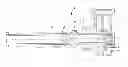
FIG. 1 is a sectional view of a device according to an embodiment of the invention for driving an auxiliary unit; and
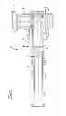
FIG. 2 is a three-dimensional top view of an exemplary coupling element on the driveshaft side.
DETAILED DESCRIPTION OF THE DRAWINGS
FIG. 1 is a sectional view of an exemplary device 1 according to the invention for driving an auxiliary unit 2. A driveshaft 3—in the present embodiment, a camshaft of an internal-combustion engine (not shown)—is provided for driving the auxiliary unit 2. In the present embodiment, the camshaft is hollow with a shrunk-on cam. Further embodiments may, for example, involve a crankshaft or any other driveshaft of the internal-combustion engine.
On a face end, the driveshaft 3 has a driveshaft-side coupling element 8, which is non-rotatably connected with the driveshaft 3. In a further embodiment, the driveshaft-side coupling element 8 may also be formed by the driveshaft 3 itself. The driveshaft-side coupling element 8 represents one side of a coupling 5, with a shaft end having an interior profile, a unit shaft 4 of the auxiliary unit 2 having an exterior profile complementary to this interior profile. Particularly preferably, the interior and the exterior profiling is a polygonal profile.
In the present embodiment, the auxiliary unit 2 is a high-pressure pump, which has a bearing 6 for the unit shaft 4. The bearing 6 is arranged on the side opposite the driveshaft 3, which, in the present embodiment, is a deep-groove ball bearing. In addition, the unit shaft 4 has a cam 7 for operating the high-pressure pump.
The unit shaft 4 has the first bearing 6 on the side facing away from the coupling 5, which coupling 5 is a second bearing for the unit shaft 4.
Accordingly, a static redundancy will therefore be avoided as a result of the bearings 5, 6.
In the present embodiment, the unit shaft 4 has the cam 7, which generates an alternating torque during the operation of the device, in which case, particularly preferably, the polygonal profile corresponds with this alternating torque. This means that the polygonal profile is oriented such that the alternating torque is eliminated as much as possible.
In a further embodiment, only the driveshaft 3 may have a cam, in which case, the polygonal profile also corresponds with this alternating torque.
Particularly preferably, the shaft end having the exterior profile has a circumferential radius in the axial direction, whereby a tolerance compensation in the axial direction or an angular tolerance compensation becomes possible. In the particularly preferred embodiment, the auxiliary unit 2 is a high-pressure fuel pump.
A coupling solution having a polygonal profile is therefore provided for coupling a driveshaft 3, for example, an intake or exhaust camshaft, a crankshaft, etc. and a unit shaft 4, such as a driveshaft of a high-pressure pump, in which case the coupling simultaneously takes over the bearing of one side of the unit shaft 4.
The unit shaft 4 is normally shaped as a camshaft. The lateral forces arising at the cam 7 are absorbed by the separate bearing 6 and the coupling 5. By means of the lateral forces, the coupling that is subject to play is always pressed onto a defined contact stop, which has acoustic advantages. In the case of a simultaneous radial loading, for example, by means of a pump tappet, onto a cam provided on the shaft, an acoustically advantageous rolling movement takes place during the change of the torque within the scope of the play between the driveshaft-side coupling element 8 and the unit shaft 4. The bearing 5 may have a polygonal profile with three, four or two corners, preferably corresponding to the number of pump lobe elevations or to a different number. This embodiment can preferably be combined with the simultaneous radial loading of the driven shaft by the construction of the polygonal profile by two tangentially adjoining radii. The coupling 5 thereby becomes tolerant with respect to the offset angle of the shafts 3, 4 as a result of a preferably crowned construction by means of the circumferential radius.
FIG. 2 is a three-dimensional top view of the driveshaft-side coupling element 8 with a shaft end 9 having an interior profile, in this embodiment having a polygonal profile, into which the corresponding exterior polygonal profile of the unit shaft 4 can be inserted. Furthermore, in this embodiment, the driveshaft-side coupling element 8 has three raised areas 11, on the basis of which a sensor, which is not shown, can detect the absolute angular position of the driveshaft 3. On the side facing away from the shaft end 9 with the interior profile, the driveshaft-side coupling element 8 has an exterior profile 10 which is used as an anti-twist protection between the driveshaft-side coupling element 8 and the driveshaft 3.
By means of the further development according to the invention, a cost-effective, acoustically inconspicuous, tolerance-insensitive coupling solution is achieved for using, for example, a high-pressure pump camshaft on an existing intake or exhaust camshaft or any other shaft.
LIST OF REFERENCE NUMBERS
- 1 Device
- 2 Auxiliary unit
- 3 Driveshaft
- 4 Unit shaft
- 5 Coupling
- 6 Bearing
- 7 Cam
- 8 Driveshaft-side coupling element
- 9 Shaft end having an interior profile
- 10 Exterior profile
- 11 Raised area
The foregoing disclosure has been set forth merely to illustrate the invention and is not intended to be limiting. Since modifications of the disclosed embodiments incorporating the spirit and substance of the invention may occur to persons skilled in the art, the invention should be construed to include everything within the scope of the appended claims and equivalents thereof.
Claims
What is claimed is:1. A device for driving an auxiliary unit by a rotatably disposed driveshaft of an internal-combustion engine, the device comprising:
a unit shaft of the auxiliary unit;
a coupling by which the driveshaft and the unit shaft are coupled in a mutually operative position;
a first bearing arranged on a side of the unit shaft facing away from the coupling; and
a second bearing of the unit shaft being provided by the coupling.
2. The device according to claim 1, wherein the auxiliary unit is a high-pressure fuel pump.
3. The device according to claim 1, wherein the coupling comprises a shaft end having an interior profile and a complementary shaft end having an exterior profile.
4. The device according to claim 3, wherein the complementary interior and exterior profiles are polygonal profiles.
5. The device according to claim 4, wherein at least one of the drive shaft and the unit shaft has a cam that generates an alternating torque during operation of the device, said polygonal profiles corresponding to the alternating torque.
6. The device according to claim 3, wherein the shaft end with the exterior profile has a circumferential radius in an axial direction.
7. The device according to claim 4, wherein the shaft end with the exterior profile has a circumferential radius in an axial direction.
8. The device according to claim 5, wherein the shaft end with the exterior profile has a circumferential radius in an axial direction.
Images & Drawings included:

Sources:
- United States Patent and Trademark Office - verify current appl. status at the USPTO↗
Similar patent applications:
- » 20150025688
CONTROL UNIT FOR FURNITURE ADJUSTMENT DRIVES AND AUXILIARY DEVICE FOR A CONTROL UNIT - » 20240221564
Display panel using auxiliary driving units and electronic device - » 20120282020
Device for Coupling a Drive Shaft of an Auxiliary Unit of a Commercial Vehicle Having a Gear Drive and Method for Producing Said Device - » 20090280939
Drive device for at least one machine auxiliary unit - » 20060050604
Transmission unit particularly for driving the screw feeders and auxiliary user devices of mixing trucks
Recent applications in this class:
- » 20250035007 2025-01-30
LUBRICANT PUMP SYSTEM AND METHOD FOR AIRCRAFT ENGINE - » 20230417153 2023-12-28
Lubricant pump system and method for aircraft engine - » 20230193776 2023-06-22
Variable speed pumping system with electric pump motor generator - » 20220186629 2022-06-16
Miniaturized turbogenerator for the direct electrical propulsion of automotive, urban air mobility, and small marine vehicles - » 20210087943 2021-03-25
FIVE CYLINDER PLUNGER PUMP - » 20200131924 2020-04-30
Gearbox ratio change - » 20190249560 2019-08-15
Angular velocity stepping and methods of use in turbomachinery - » 20190024528 2019-01-24
Compressor train start-up using variable inlet guide vanes - » 20180202308 2018-07-19
Self-Sustaining Power Generation System (SPGS) - » 20170138213 2017-05-18
Combined pump and turbine
Recent applications for this Assignee:
- » 20250236179 2025-07-24
METHOD FOR OPERATING A BRAKE CONTROL SYSTEM, BRAKE CONTROL SYSTEM, COMPUTER PROGRAM, AND COMPUTER-READABLE STORAGE MEDIUM - » 20250109792 2025-04-03
Mounting assembly for a coupler mechanism of a motor vehicle - » 20250077042 2025-03-06
Method for increasing safety during the operation of a device - » 20250042351 2025-02-06
Arrangement for Holding a Sidewall Element on a Bodyshell Part of a Vehicle, Bracket and Vehicle - » 20250026428 2025-01-23
Handlebar Assembly for a Motor Vehicle, and Motor Vehicle Having a Handlebar Assembly of This Kind - » 20250020305 2025-01-16
Decorative element for a motor vehicle, and production method for a decorative element - » 20250001843 2025-01-02
Motor Vehicle With a Side Door - » 20240426445 2024-12-26
Motor Vehicle Lighting Module - » 20240383554 2024-11-21
Leaning vehicle - » 20240383416 2024-11-21
Motor vehicle having a plurality of control devices which provide different vehicle functions in the motor vehicle and method for configuring the control devices and control device