Cryogenic Cooling Method and Installation Using Liquid CO2 and Employing Two Exchangers in Series
US20130081789A1
2013-04-04
13/701,326
2011-05-05
Abstract:
A method and installation using liquid CO2 as a cryogenic fluid for transferring cold energy to products, wherein liquid CO2 is sent into a heat exchanger system including first and second heat exchangers connected in series. The liquid CO2 is supplied to the first heat exchanger where it evaporates. Gaseous CO2 from the first exchanger is supplied to the second heat exchanger. The atmosphere surrounding the products is blown across the heat exchangers to provide a cooled atmosphere with which to cool the products. The latent heat of vaporization of the liquid CO2 in the first heat exchanger and the sensible heat of the gaseous CO2 in the second heat exchanger satisfies the cooling requirement of the products. The first exchanger is kept at a pressure higher than the triple point pressure for CO2, whereas the second exchanger is held at atmospheric pressure or at a pressure between the triple point of the fluid and atmospheric pressure.
Inventors:
- Didier Pathier 10 🇫🇷 Voisins Le Bretonneux, France
- Thierry Dubreuil 6 🇫🇷 Boissets, France
- Mohammed Youbi-Idrissi 7 🇫🇷 Massy, France
Assignee:
- L'Air Liquide Societe Anonyme Pour L'Etude Et L'Exploitation Des Procedes Georges Claude 1,444 🇫🇷 Paris, France
Interested in similar patents?
Get notified when new applications in this technology area are published.
Classification:
F28D15/02 » CPC main
Heat-exchange apparatus with the intermediate heat-transfer medium in closed tubes passing into or through the conduit walls ; Heat-exchange apparatus employing intermediate heat-transfer medium or bodies in which the medium condenses and evaporates, e.g. heat pipes
Description
The present invention relates to the field of cooling processes employing CO2.
The use of CO2 in such cooling processes is, as is known, very advantageous, since this fluid has a solid phase at −80° C. at atmospheric pressure, thereby allowing dry ice to be used in certain applications, this ice being very effective, especially as far as localized cooling without refrigeration equipment is concerned. Solid CO2 has many applications, such as for example dry ice bags, which are loaded into containers for transporting food or pharmaceutical products, or which indeed may be used to keep meals cool in the field of aerial transportation.
However, when this gas is used in (“indirect injection”) heat exchangers, typically tube or finned heat exchangers, this advantage turns into a drawback because the untimely appearance of solid CO2 (carbon snow) in an exchanger rather rapidly leads to the latter becoming blocked.
Therefore, to prevent this drawback of transition into the solid phase, it is sought to prevent the solid phase of CO2 from appearing, and conditions are therefore preferred that make it possible to keep the CO2 in liquid or gaseous form in the entire exchanger.
In order to exchange heat while ensuring the CO2 remains in its gaseous or liquid phase (vaporization of the liquid CO2 without running the risk of forming solid CO2), the pressure in the tube must be kept above the theoretical pressure of 5.18 bar corresponding to the triple point pressure of this fluid. In practice, the system is restricted as it were to a pressure of 6 to 7 bar, thus ensuring a safety margin of 0.82 to 1.82 bar.
Whereas the sublimation temperature of solid CO2 at atmospheric pressure is −80° C., keeping the pressure in the exchanger at 6 bar relative increases the vaporization temperature to about −50° C.
However, carrying out the heat exchange at 6 bar and not at atmospheric pressure slightly decreases the cooling capacity of the CO2. Specifically, when a kilogram of CO2 is taken out of storage, for example under standard conditions such as 20 bar absolute/−20° C., and enters into an exchanger, it releases 277.97 kJ/kg if it is discharged at −50° C. in gaseous form at 6 bar relative, whereas the same amount of CO2 releases 292.6 kJ/kg when it is discharged at −50° C. at atmospheric pressure, i.e. an increase of 5%.
By way of example, CO2 discharged at 6 bar after passing through an exchanger is used in applications such as refrigerated trucks but also in freezing tunnels or chambers. In these applications, a heat exchanger is supplied with liquid CO2 which, by evaporating in this exchanger, extracts heat from the medium to be cooled and thus produces the desired cooling. Cooling of the products to be cooled is achieved via heat exchange with the internal air of the tunnel, chamber or truck, via blowing means associated with each exchanger.
It will therefore be understood that it would be advantageous to be able to provide a technical solution allowing heat exchange in a tube or finned heat exchanger (indirect exchange), at exchanger temperatures that are nonetheless low (typically −50° C.) without of course running the risk of forming snow and losing the cooling capacity of the CO2 following its expansion from 6 bar to atmospheric pressure.
As will be seen in more detail below, the present invention provides a new exchange solution, the main features of which may be summarized as follows:
-
- the solution proposed here relates to the exchanger configuration adopted, the exchanger used, which may for example be a tube or finned heat exchanger, consisting of two exchangers connected in series;
- the first exchanger can be supplied with liquid CO2 (for example under standard conditions such as −20° C./20 bar), the liquid encountering, before it enters the first exchanger, a thermostatic regulator or a temperature probe/regulator/valve assembly, or any other means allowing the flow rate of the CO2 entering the 1st exchanger to be matched to the cooling requirements in question, i.e. allowing the “excess” temperature, or, in other words, the temperature difference between the temperature corresponding to the saturation vapor pressure (for example at 6 bar, −53.1° C.) and for example −50° C., which corresponds to 3.1° of excess, to be controlled;
- the pressure in the first exchanger is kept above 5.18 bar relative, i.e. the temperature of the phase change of the CO2 (the formation of snow thus being prevented), the pressure is, for example, kept at 6 bar absolute by virtue of a back-pressure regulator or a pressure sensor/regulator/valve assembly, placed at the outlet of the first exchanger;
- this arrangement makes it possible to ensure that the CO2 in the first exchanger is only present strictly in its gas/liquid two-phase form without at any point the conditions used allowing a solid to form;
- the minimum temperature obtained in this first exchanger is then about −50° C.; and
- according to one embodiment, the back-pressure regulator at the outlet of the first exchanger is preceded by a phase separator in order to prevent any liquid from exiting the first exchanger.
The back-pressure regulator and the outlet of the first exchanger will possibly be installed in an upper part of the complete installation to prevent liquid from escaping, but configurations where the two exchangers are located at the same level may also be envisioned.
The optional presence of the aforementioned separator increases the reliability of the system. It prevents liquid from reaching the back-pressure regulator and therefore snow from forming and causing a blockage at this point.
-
- In summary, the liquid CO2 vaporizes in the first exchanger and the gas formed in this exchanger, for example at 6 bar, is released in the second exchanger;
- this second exchanger is at atmospheric pressure (or in any case at a pressure below the triple point of the fluid), the gas then expands, after entering this second exchanger at 6 bar (or more generally at the pressure maintained in the first exchanger), to atmospheric pressure (or in any case to a pressure between the triple point of the fluid and atmospheric pressure) which causes cooling, namely to a temperature typically between −60° C. and −70° C.;
- and therein lies the advantage of the present invention, since the cooling produced by expansion to atmospheric pressure is used by the second exchanger, and thus all the energy contained in the CO2 is used.
The present invention thus relates to a process employing liquid CO2 as a cryogenic fluid for cooling products, this process being an “indirect injection” cooling process where the liquid CO2 is transferred to a heat exchanging system where it evaporates, the removal of heat from the products occurring by an exchange between the atmosphere surrounding the products and the cold walls of the heat exchanger, this process being noteworthy in that the exchanging system consists of two exchangers connected in series, the first exchanger being kept at a pressure above the triple point pressure of CO2, whereas the second exchanger is itself kept at atmospheric pressure or at a pressure between the triple point of the fluid and atmospheric pressure.
The present invention also relates to an installation for cooling products using liquid CO2, the installation employing an “indirect injection” process, and comprising:
-
- a heat exchanging system through which the liquid CO2 can pass; and
- blowing means associated with the heat exchanging system, able to bring the atmosphere surrounding the products into contact with cold walls of the heat exchanging system,
the installation being noteworthy in that the following measures are implemented:
-
- the exchanging system consists of two exchangers connected in series;
- the installation comprises, upstream of the inlet of the first exchanger, a means able to adjust the CO2 flow rate and to control the excess temperature thereof relative to the corresponding temperature at saturated vapor pressure, such as a thermostatic regulator or a temperature probe/regulator/valve assembly;
- the installation comprises a means for keeping the pressure in the first exchanger at a pressure above the triple point pressure of CO2, preferably a back-pressure regulator or a pressure sensor/regulator/valve assembly; and
- the second exchanger is at atmospheric pressure or at a pressure between the triple point of the fluid and atmospheric pressure.
The installation therefore comprises, if required, a means for keeping the pressure in the second exchanger at atmospheric pressure or at a pressure between the triple point of the fluid and atmospheric pressure.
Other features and advantages of the present invention will become more clearly apparent from the following description given by way of completely nonlimiting illustration with regard to appended FIGS. 1 and 2, which are partial schematic representations of installations according to the invention, FIG. 3 showing the temperature profile expected in the exchanger assembly on the CO2 and heat-transfer fluid (air) sides.
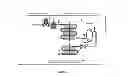
The following elements, and therefore the course followed by the CO2, in its various phases, in the installation, may be seen in FIG. 1:
-
- the first exchanger is able to be supplied with liquid CO2 (for example under standard conditions such as −20° C./20 bar), the liquid encountering, before it enters the first exchanger, a thermostatic regulator (downstream of point 1) or any other means allowing the flow rate of the CO2 reaching the first exchanger to be matched to the cooling requirements in question, i.e. to control the excess temperature, or, in other words, the temperature difference between the temperature corresponding to the saturated vapor pressure (for example 6 bar, −53.1° C.) and for example −50° C., which corresponds to 3.1° C. of excess temperature.
Downstream of point 2 the fluid enters into the first exchanger.
-
- a pressure higher than 5.18 bar relative is maintained in this first exchanger, temperature of the phase change of CO2 (thus allowing the formation of snow to be prevented), by virtue of the back-pressure regulator placed at the outlet of this first exchanger in the figure (back-pressure regulator placed between points 3 and 4);
- this arrangement makes it possible to ensure that the CO2 in the first exchanger is present only in a strictly liquid/gas two-phase form, without at any point the conditions used allowing a solid to form;
- the minimum temperature obtained in this first exchanger is then −50° C.;
- in the embodiment illustrated here, the back-pressure regulator at the outlet of the first exchanger is preceded by a phase separator (between points 3′ and 3), in order to prevent any escape of liquid from the first exchanger. In this embodiment, the back-pressure regulator and the outlet of the first exchanger are installed in an upper part of the complete installation, to prevent escape of liquid.
- at the outlet of point 4 and therefore of the back-pressure regulator, the gas enters into the second exchanger, which it exits at point 5.
The table below collates the thermodynamic properties of the fluid at various points in FIG. 1, and makes it possible to show unambiguously the advantages of the invention in terms of cooling efficiency. The table especially illustrates a number of temperature conditions, at the outlets of the exchangers.
In addition, to clearly show the benefit of the present invention, the energy efficiency of a system not employing the invention and a system employing the present invention are compared, in the case where the final temperature in the exchanger is −25° C. and in the case where the final temperature in the exchanger is −5° C.
Considering the first case (the final temperature in the exchanger being −25° C.)
-
- for a system employing a single exchanger: 1 kg of CO2 releases 457−154.5=302.5 kJ;
- for a system employing two exchangers according to the invention: 1 kg of CO2 releases 464.5−154.5=310 kJ; i.e. a 2.5% increase in energy.
In the second illustrative case, where the final temperature of the exchanger is −5° C.:
-
- for a system employing a single exchanger: 1 kg of CO2 releases 474.6−154.5=320.1 kJ;
- for a system employing two exchangers according to the invention: 1 kg of CO2 releases 480.8−154.5=326.3 kJ; i.e. a 1.9% increase in energy.
| TABLE 1 | ||||
| Point on the figure | T (° C.) | P (bar abs) | H (kJ/kg) | |
| 1 | −20.0 | 19.7 | 154.5 | |
| 2 | −53.1 | 6 | 154.5 | |
| 3′ | −53.1 | 6 | 431.6 | |
| 3 | −50.0 | 6 | 434.5 | |
| 3 standard | −25.0 | 6.0 | 457.0 | |
| 3 standard | −5.0 | 6.0 | 474.6 | |
| 4 | −63.1 | 1 | 434.5 | |
| 5 | −25.0 | 1 | 464.5 | |
| 5 | −5.0 | 1 | 480.8 | |
The temperature profile expected in the exchanger on the CO2 and heat-transfer fluid (air for example in an application such as the transportation of frozen products) sides, shown in FIG. 3, demonstrates that the present invention also has a beneficial impact on the temperature profile in the exchangers: the fact that the second exchanger stage is at atmospheric pressure makes it possible to take advantage of a cryogenic effect as the curves in FIG. 3 show.
If FIG. 1 showed a first embodiment of the invention, FIG. 2, for its part, shows another, which will not be described in greater detail here. As will become clear on examination of the figure, it illustrates a variant employing:
-
- upstream of the first exchanger, an assembly consisting of a calibrated orifice and a temperature-controlled valve, rather than a thermostatic regulator; and
- at the outlet of the first exchanger of the installation, a pressure sensor/regulator/valve assembly, rather than a back-pressure regulator.
Claims
1-9. (canceled)
10. A process for indirectly cooling products using liquid CO2, comprising the steps of:
supplying liquid CO2 to a heat exchanging system at which the liquid CO2 evaporates, the heat exchanging system comprising first and second heat exchangers connected in series, the first heat exchanger being kept at a pressure above the triple point pressure of CO2, the second heat exchanger being kept at atmospheric pressure or at a pressure between the triple point pressure of CO2 and atmospheric pressure; and
removing heat from the products through heat exchange between cold walls of the heat exchangers and an atmosphere surrounding the products.
11. The process of claim 10, further comprising:
adjusting a flow rate of the liquid CO2 supplied to the first heat exchanger with a liquid CO2 flow rate adjustment element disposed upstream of the first heat exchanger, the adjustment being based upon a cooling requirement of the products to be cooled, the liquid CO2 flow rate adjustment element comprising either a thermostatic regulator or a temperature probe/regulator/valve assembly;
maintaining a pressure in the first heat exchanger above the triple point pressure of CO2; and
transferring gaseous CO2, formed from vaporization of the liquid CO2 in the first heat exchanger, to the second heat exchanger
12. The process of claim 11, wherein the pressure in the first heat exchanger is kept at a pressure above the triple point pressure of CO2 by virtue of a back-pressure regulation device that is placed at an outlet of the first heat exchanger, the back-pressure regulation device comprising either a back-pressure regulator or a pressure sensor/regulator/valve assembly.
13. The process of claim 12, wherein a phase separator is disposed in fluid communication between the outlet of the first heat exchanger and the back-pressure regulation device, the phase separator preventing liquid CO2 from flowing into the second heat exchanger.
14. An installation for cooling products using liquid CO2, comprising, a first heat exchanger receiving liquid CO2, a second heat exchanger receiving gaseous CO2 formed from vaporization of the liquid CO2 in the first heat exchanger, a blower operatively associated with the first and second heat exchangers, a liquid CO2 flow rate adjustment element disposed upstream of the first heat exchanger, and a back-pressure regulation device, wherein:
the liquid CO2 flow rate adjustment element is adapted and configured to adjust a flow rate of liquid CO2 into the first heat exchanger based upon a cooling requirement of the products to be cooled and comprises either a thermostatic regulator or a temperature probe/regulator/valve assembly;
the blower is adapted and configured to blow an atmosphere surrounding the products to be cooled into contact with cold walls of the heat exchange system;
the first and second heat exchangers are connected in series;
the back-pressure regulation device is disposed downstream of an outlet of the first heat exchanger and is adapted and configured to maintain a pressure in the first heat exchanger above the triple point pressure of CO2.
15. The installation of claim 14, further comprising a phase separator inserted upstream of the back-pressure regulation device.
16. The installation of claim 14, wherein the back-pressure regulation device comprises either a back-pressure regulator or a pressure sensor/regulator/valve assembly.
Images & Drawings included:


Sources:
- United States Patent and Trademark Office - verify current appl. status at the USPTO↗
Recent applications in this class:
- » 20250164193 2025-05-22
HEAT TRANSFER APPARATUS AND METHOD - » 20250123058 2025-04-17
MULTILAYER HIGH ASPECT RATIO MICROCHANNEL DEVICE - » 20240344772 2024-10-17
HEAT SINK APPARATUS - » 20240125558 2024-04-18
HEAT EXCHANGER - » 20240077259 2024-03-07
HEAT PIPES AND VAPOR CHAMBERS MANUFACTURED USING A VACUUM PROCESS - » 20230106794 2023-04-06
Heat sink - » 20220260319 2022-08-18
THERMOELECTRIC POWER GENERATION SYSTEM - » 20220214115 2022-07-07
Vapor chamber - » 20210318072 2021-10-14
Cooling device with superimposed fin groups - » 20210285728 2021-09-16
Immersion cooling system
Recent applications for this Assignee:
- » 20250166974 2025-05-22
SULFUR-CONTAINING MOLECULES FOR HIGH ASPECT RATIO PLASMA ETCHING PROCESSES - » 20250164074 2025-05-22
TANK FOR STORING LIQUEFIED GAS AND FLUID TRANSFER METHOD - » 20250162866 2025-05-22
METHOD FOR CRACKING AMMONIA - » 20250161976 2025-05-22
NEW LOW-K MATERIALS DERIVED BY HYDROSILYLATION AND METHODS OF USING THEM FOR DEPOSITION - » 20250155175 2025-05-15
REFRIGERATION DEVICE AND METHOD - » 20250154042 2025-05-15
MELTING DEVICE - » 20250149609 2025-05-08
FUEL CELL - » 20250137596 2025-05-01
VALVE FOR PRESSURIZED FLUID AND A CONTAINER OR A SET OF CONTAINERS FOR PRESSURIZED FLUID - » 20250129889 2025-04-24
METHOD AND DEVICE FOR TRANSFERRING CRYOGENIC FLUID - » 20250121315 2025-04-17
FACILITY FOR RECOVERING CO2 FROM A FEED GAS FLOW