Lamp
US20130106282A1
2013-05-02
13/809,612
2011-07-12
✅ Patent granted
US 9,240,302 B2
2016-01-19
WO; PCT/GB2011/001049; 20110712
WO; WO2012/007714; 20120119
Hai L Nguyen
Bay State IP, LLC
2032-03-28
Abstract:
To the common point C of two transistors of a magnetron, switched converter power circuit is connected a coupling capacitor which provides input to a starter circuit. A transistor switch is in series with the capacitor and a diode. When the switch is off no current flows in D11. When the switch is made, D11 conducts during alternate halves of cycles present at C. A second diode also conducts and allows current to pass through discharge capacitor. This progressively charges until the voltage across it reaches the breakdown voltage of a gas discharge tube GTD. Whereupon the capacitor discharges through the primary winding of transformer TR2. The secondary winding has many more turns and a starter voltage is induced in the starter electrode. This is isolated from the Faraday cage and terminates adjacent the crucible, close to the void.
Assignee:
- Ceravision Limited 18 🇬🇧 Milton Keynes, United Kingdom
Applicant:
Interested in similar patents?
Get notified when new applications in this technology area are published.
Classification:
H01J65/044 » CPC further
Lamps without any electrode inside the vessel; Lamps with at least one main electrode outside the vessel; Lamps in which a gas filling is excited to luminesce by an external electromagnetic field or by external corpuscular radiation, e.g. for indicating plasma display panels by an external electromagnetic field the field being produced by a separate microwave unit
H05B41/24 » CPC further
Circuit arrangements or apparatus for igniting or operating discharge lamps; Circuit arrangements in which the lamp is fed by high frequency ac, or with separate oscillator frequency
H01J25/50 » CPC main
Transit-time tubes, e.g. klystrons, travelling-wave tubes, magnetrons Magnetrons, i.e. tubes with a magnet system producing an H-field crossing the E-field
H01J65/04 IPC
Lamps without any electrode inside the vessel; Lamps with at least one main electrode outside the vessel Lamps in which a gas filling is excited to luminesce by an external electromagnetic field or by external corpuscular radiation, e.g. for indicating plasma display panels
H05H1/46 » CPC further
Generating plasma; Handling plasma; Generating plasma using applied electromagnetic fields, e.g. high frequency or microwave energy
H05H1/46 » CPC further
Generating plasma; Handling plasma; Generating plasma using applied electromagnetic fields, e.g. high frequency or microwave energy
Description
The present invention relates to a lamp, incorporating a magnetron powered light source.
In European Patent No EP1307899, granted in our name there is claimed a light source a waveguide configured to be connected to an energy source and for receiving electromagnetic energy, and a bulb coupled to the waveguide and containing a gas-fill that emits light when receiving the electromagnetic energy from the waveguide, characterised in that:
- (a) the waveguide comprises a body consisting essentially of a dielectric material having a dielectric constant greater than 2, a loss tangent less than 0.01, and a DC breakdown threshold greater than 200 kilovolts/inch, 1 inch being 2.54 cm,
- (b) the wave guide is of a size and shape capable of supporting at least one electric field maximum within the wave guide body at at least one operating frequency within the range of 0.5 to 30 GHz,
- (c) a cavity depends from a first side of the waveguide,
- (d) the bulb is positioned in the cavity at a location where there is an electric field maximum during operation, the gas-fill forming a light emitting plasma when receiving microwave energy from the resonating waveguide body, and
- (e) a microwave feed positioned within the waveguide body is adapted to receive microwave energy from the energy source and is in intimate contact with the waveguide body.
In our International Application No PCT/GB2010/000911, applied for on 6th May 2010, (“Our 1st Light Source and Starter Application”) we have described and claimed a light source to be powered by microwave energy, the source having:
-
- a solid plasma crucible of material which is lucent for exit of light therefrom, the plasma crucible having a closed void in the plasma crucible,
- a Faraday cage surrounding the plasma crucible, the cage being at least partially light transmitting for light exit from the plasma crucible, whilst being microwave enclosing,
- a fill in the closed void of material excitable by microwave energy to form a light emitting plasma therein, and
- an antenna arranged within the plasma crucible for transmitting plasma-inducing microwave energy to the fill, the antenna having:
- a connection extending outside the plasma crucible for coupling to a source of microwave energy;
the light source also including:
- a connection extending outside the plasma crucible for coupling to a source of microwave energy;
- a controllable source of microwaves coupled to the antenna connection;
- a starter for starting a plasma in the fill in the closed void,
- a detector for detecting starting of the plasma and
- a control circuit for powering the source at low power initially and simultaneously with the starter and switching off the starter and increasing power of the microwave source after detection of starting of the plasma.
In Our 1st Light Source and Starter Application and in the present application, we use the following definitions:
-
- “microwave” is not intended to refer to a precise frequency range. We use “microwave” to mean the three order of magnitude range from around 300 MHz to around 300 GHz;
- “lucent” means that the material, of which an item described as lucent is comprised, is transparent or translucent;
- “plasma crucible” means a closed body enclosing a plasma, the latter being in the void when the void's fill is excited by microwave energy from the antenna;
- “Faraday cage” means an electrically conductive enclosure of electromagnetic radiation, which is at least substantially impermeable to electromagnetic waves at the operating, i.e. microwave, frequencies.
EP1307899 and Our 1St Light Source and Starter Application have in common that they are in respect of:
A microwave plasma light source having:
-
- a Faraday cage delimiting a waveguide;
- a body of solid-dielectric material at least substantially embodying the waveguide within the Faraday cage;
- a closed void in the waveguide containing microwave excitable material; and
- provision for introducing plasma exciting microwaves into the waveguide;
- the arrangement being such that on introduction of microwaves of a determined frequency a plasma is established in the void and light is emitted.
Such a light source is referred to herein as a “Microwave Plasma Light Source” or MPLS.
We also refer below to the Microwave Plasma Light Source of Our 1st Light Source and Starter Application as a Light Emitting Resonator or LER.
In our International Application No PCT/GB2011/000920, filed on 17 Jun. 2011 (“Our Magnetron Power Supply Application”), we have described and claimed a power supply for a magnetron comprising:
-
- a DC voltage source;
- a converter for raising the output voltage of the DC voltage source, the converter having:
- a capacitative-inductive resonant circuit,
- a switching circuit adapted to drive the resonant circuit at a variable frequency above the resonant frequency of the resonant circuit, the variable frequency being controlled by a control signal input to provide an alternating voltage,
- a transformer connected to the resonant circuit for raising the alternating voltage,
- a rectifier for rectifying the raised alternating voltage to a raised DC voltage for application to the magnetron;
- means for measuring the current from the DC voltage source passing through the converter;
- a microprocessor programmed to produce a control signal indicative of a desired output power of the magnetron; and
- an integrated circuit arranged in a feed back loop and adapted to apply a control signal to the converter switching circuit in accordance with a comparison of a signal from the current measuring means with the signal from the microprocessor for controlling the power of the magnetron to the desired power.
This power supply (i.e. the one of Our Magnetron Power Supply Application) is an improvement on an earlier power supply utilising a differently arranged operational amplifier and a differently arranged microprocessor.
Again in this application, we use the further additional definition: “Magnetron, Switched Converter Power Circuit” or MSCPC means the following components of the power supply:
-
- the converter adapted to be driven by a DC voltage source and produce an alternating current output, the converter having:
- the resonant circuit including an inductance and a capacitance (“LC circuit”) exhibiting a resonant frequency and
- the switching circuit adapted to switch the inductance and the capacitance to generate a switched alternating current having a frequency greater than that of the resonance of the LC circuit;
- the output transformer for increasing the voltage of the output alternating current; and
- the rectifier and smoothing circuit connected to the secondary circuit of the output transformer for supplying increased voltage to the magnetron;
- the converter adapted to be driven by a DC voltage source and produce an alternating current output, the converter having:
The object of the present invention is to provide an improved lamp utilising a MSCPC and a starter improved from that disclosed in Our 1st Light Source and Starter Application.
According to the invention there is provided a magnetron powered lamp, the lamp comprising:
-
- a Microwave Plasma Light Source;
- a magnetron arranged to power the MPLS;
- a Magnetron, Switched Converter Power Circuit arranged to power the magnetron;
- a microprocessor arranged to control the MSCPC;
- a starter for starting a plasma in the fill in the closed void of the MPLS, the starter comprising:
- a starter electrode arranged to apply starter voltage to the closed void,
- a starter circuit including:
- a capacitor,
- means for selectively charging the capacitor from a switched point in the MSCPC,
- means for discharging the capacitor,
- a transformer having:
- a primary winding arranged to receive discharge current from the capacitor and
- a secondary winding arranged to generate the starter voltage, the secondary winding being connected to the starter electrode for application of starter voltage to the closed void and
- a detector for detecting starting of the plasma;
wherein:
- the microprocessor is arranged to select charging of the capacitor for starting of the plasma until the detector detect that the plasma has started.
Whilst it is envisaged that the selective charging means could be an electronic switch normally isolating the discharging means from the switched point of the power circuit, in the preferred embodiment, the selective charging means is a electronic switch normally grounding the discharging means. In either instance, the state of the switch is changed for starter operation.
Also in the preferred embodiment, the means for discharging the capacitor is a gas discharge unit. Alternatively trigger diode could be employed.
Further in the preferred embodiment, the microprocessor controls the MSCPC via an integrated circuit arranged in a feed back loop and adapted to apply a control signal to the converter switching circuit in accordance with a comparison of a signal from means for measuring MSCPC with a signal from the microprocessor for controlling the power of the magnetron to a desired power.
To help understanding of the invention, a specific embodiment thereof will now be described by way of example and with reference to the accompanying drawings, in which:
FIG. 1 is a block diagram of a magnetron powered lamp of the invention;
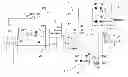
FIG. 2 is a more detailed circuit diagram of a Magnetron, Switched Converter Power Circuit similar to that described in Our Magnetron Power Supply Application and incorporating a starter of this invention; and
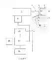
FIG. 3 is a scrap view of a variation of the diagram of FIG. 1.
Referring to FIG. 1, the LER lamp is shown diagrammatically as having a quartz crucible 1 with a central closed void 2 containing material 3 excitable by microwaves as a plasma. The crucible is enclosed in a Faraday cage 4 defining a waveguide, in which microwaves resonate in operation of the lamp. An antenna 5, having a coaxial connection 6 extending from a matching circuit wave guide 7, passes into the crucible adjacent to the fill. Remote from the crucible a magnetron 8 is arranged to transmit microwaves into the wave guide for onwards transmission to the crucible.
Extending close to the end of the void is a starter electrode 11 and adjacent to this is mounted a photodiode 12 for detecting whether the plasma has been lit and is emitting light.
A power supply 21 for the magnetron 8 is connected to a voltage source 22 and a microprocessor 23. As shown in FIG. 2, the power supply comprises a quasi-resonant converter 101 having MOSFET field effect switching transistors T1,T2. These are switched by an integrated circuit IC1. An inductance L1 and primary coil of a transformer TR1 are connected in series to the common point C of the transistors and capacitors C3,C4 connected beyond the primary coil back to the remote contact of the transistors. The inductances and the capacitors have a resonant frequency, above which the converter is operated, whereby it appears to be primarily an inductive circuit as regards the down-stream magnetron circuit. This comprises four half bridge diodes D3,D4,D5,D6 and smoothing capacitors C5,C6, connected to the secondary winding of the transformer and providing DC current to the magnetron 8. The windings ratio of the transformer is 10:1, whereby voltage of the order of 4000 volts is applied to the magnetron, the augmented mains DC voltage on line 105 being 400 volts (at least in Europe).
To the common point C of the transistors is connected a coupling capacitor C11 which provides input to a starter circuit 24. A transistor switch 25 is in series with the capacitor C11 and a diode D1. When the switch is off no current flows in D11. When the switch is made, D11 conducts during alternate halves of cycles present at C. A second diode D12 also conducts and allows current to pass through discharge capacitor C12. This progressively charges until the voltage across it reaches the breakdown voltage of a gas discharge tube GTD. Whereupon the capacitor discharges through the primary winding of transformer TR2. The secondary winding has many more turns and a starter voltage is induced in the starter electrode 11. This is isolated from the Faraday cage 4 and terminates adjacent the crucible, close to the void 2.
Every time the discharge capacitor discharges, the void is pulsed. The magnetron is being driven—the starter being able to operate only as a result of the converter operating. Once a plasma in the void establishes, this is detected by a photodiode 12 adjacent the starter electrode 11. Presence of plasma is signalled to the microprocessor which opens the transistor switch 25.
For completeness, a current measurement resistor R1, an operational amplifier EA1 and associated components are shown for operation of the converter in accordance with Our Magnetron Power Supply Application. A further transistor switch 26 is also shown. With this the microprocessor can immediately close down the power supply, either under human control or automatically, for instance in the event of the magnetron current exceeding a limit such as when its magnets degrade.
In practical operation, with the lamp not on, the voltage source (not shown above) and the microprocessor are switched on. The microprocessor is instructed to power up the lamp in accordance with one or more protocols. The microprocessor controls the power supply to apply a low power to the magnetron and the starter to apply a starter pulse stream of a determined duration to the starter. If the plasma does not start, the pulse stream is repeated after a delay. The process is repeated until the plasma lights. Should this fails the operator is alerted. Once the plasma has lit, power to the magnetron is increased to a desired level, commensurate with desired light output from the plasma crucible.
Turning to the variant of FIG. 3, the arrangement of the discharge capacitor C11 and the gas discharge tube GTD is interchanged. They operate in an analogous way to that in which they operate in FIG. 2. The variant also includes a voltage doubler stage comprising diodes D14, D15 and capacitors C14, C15. With this arrangement, including an appropriate value GDT, doubled primary voltage is applied to the transformer TR2.
Claims
1. A magnetron powered lamp comprising:
a Microwave Plasma Light Source;
a magnetron arranged to power the MPLS;
a Magnetron, Switched Converter Power Circuit arranged to power the magnetron;
a microprocessor arranged to control the MSCPC;
a starter for starting a plasma in the fill in the closed void of the MPLS, the starter comprising:
a starter electrode arranged to apply starter voltage to the closed void,
a starter circuit including:
a capacitor,
means for selectively charging the capacitor from a switched point in the MSCPC,
means for discharging the capacitor,
a transformer having:
a primary winding arranged to receive discharge current from the capacitor and
a secondary winding arranged to generate the starter voltage, the secondary winding being connected to the starter electrode for application of starter voltage to the closed void and
a detector for detecting starting of the plasma;
wherein:
the microprocessor is arranged to select charging of the capacitor for starting of the plasma until the detector detect that the plasma has started.
2. A magnetron powered lamp as claimed in claim 1, wherein the selective charging means is an electronic switch normally isolating the discharging means from the switched point of the power circuit.
3. A magnetron powered lamp as claimed in claim 1, wherein the selective charging means is a electronic switch normally grounding the discharging means.
4. A magnetron powered lamp as claimed in claim 1, wherein the electronic switch is a transistor and the means for discharging the capacitor is a gas discharge unit.
5. A magnetron powered lamp as claimed in claim 1, wherein the electronic switch is a transistor and the means for discharging the capacitor is a trigger diode.
6. A magnetron powered lamp as claimed in claim 1, wherein the microprocessor controls the MSCPC via an integrated circuit arranged in a feed back loop and adapted to apply a control signal to the converter switching circuit in accordance with a comparison of a signal from means for measuring MSCPC with a signal from the microprocessor for controlling the power of the magnetron to a desired power.
Images & Drawings included:


Sources:
- United States Patent and Trademark Office - verify current appl. status at the USPTO↗
Similar patent applications:
- » 20100073928
Lens for LED outdoor lamp, and its applied road lamp, security lamp, tunnel lamp, park lamp, guard lamp, industrial flood lamp, and outdoor lamp - » 20080185968
Method For Lamp Life Control of a Gas Discharge Lamp, a Gas Discharge Lamp Driver Circuit, a Gas Discharge Lamp and an Assembly of a Gas Discharge Lamp and a Lamp Driver Circuit - » 20210120140
Image reading apparatus including a first lamp and second lamp that alternately turn on, wherein the first lamp turns on during reading odd-numbered lines and the second lamp turns on during reading even-numbered lines and synthesizes the first image data read from turning on the first lamp and the second image data read from turning on the second lamp - » 20150316214
Lamp holder and lamp socket and system with lamp holder and lamp socket and method for supporting a lamp socket in a lamp holder - » 20070052365
Manufacturing method of high-pressure discharge lamp, high-pressure discharge lamp, lamp unit using high-pressure discharge lamp, and image display apparatus using high-pressure discharge lamp - » 20080258622
High-pressure discharge lamp, lighting method and lighting device for high-pressure discharge lamp, high-pressure discharge lamp device, and lamp unit, image display device and headlight device - » 20060197475
High-pressure discharge lamp, lighting method and lighting device for high-pressure discharge lamp, high-pressure discharge lamp device, and lamp unit, image display device and headlight device - » 10760166
Method for manufacturing high-pressure discharge lamp, glass tube for high-pressure discharge lamp, and lamp element for high-pressure discharge lamp - » 20060076870
Discharge lamp, discharge lamp socket, discharge lamp device, and discharge lamp lighting device - » 10111067
Mercury lamp, lamp unit, method for producing mercury lamp and electric lamp
Recent applications in this class:
- » 20250079107 2025-03-06
FIBER OPTIC POWER FOR ADJUSTABLE MAGNET ASSEMBLIES - » 20240312753 2024-09-19
RADIATION INSPECTION SYSTEM AND METHOD - » 20230187164 2023-06-15
Injection-locked magnetron system based on filament injection - » 20220375709 2022-11-24
MAGNETRON CONDITION MONITORING - » 20200251300 2020-08-06
MAGNETRONS - » 20200194210 2020-06-18
High-voltage generator for providing a high-voltage pulse - » 20200194209 2020-06-18
Modulator system - » 20190318899 2019-10-17
MODULATOR SYSTEM - » 20180261419 2018-09-13
High-powered magnetron - » 20180130629 2018-05-10
A MODULATOR SYSTEM
Recent applications for this Assignee:
- » 20170125236 2017-05-04
Light source - » 20150097481 2015-04-09
Lucent waveguide electromagnetic wave - » 20140246971 2014-09-04
Microwave driven electrodeless lamp comprising magnetron without forced convective cooling - » 20140077693 2014-03-20
Crucible structure for plasma light source and manufacturing method - » 20140042901 2014-02-13
Lucent waveguide electromagnetic wave plasma light source - » 20130134872 2013-05-30
Magnetron power supply - » 20130100709 2013-04-25
Magnetron power supply - » 20130052904 2013-02-28
Method of applying a faraday cage onto the resonator of a microwave light source - » 20130040529 2013-02-14
Method of manufacturing an electrode-less incandescent bulb - » 20120293067 2012-11-22
Lamp