USE OF ADSORPTION OR ABSORPTION TECHNOLOGIES FOR THERMAL-ELECTRIC POWER PLANT COOLING
US20130118192A1
2013-05-16
13/463,548
2012-05-03
Abstract:
A hybrid cooling system adapted to provide cooling to a thermal-electric power plant includes an air-cooled condenser (ACC) adapted to provide cooling water to the thermal-electric power plant and a vapor absorption/adsorption refrigerant system (VARS) adapted to provide cooled air to the ACC. The cooled air is used by the ACC to condense steam to produce the cooling water.
Inventors:
- Baolan Shi 3 🇺🇸 Palo Alto, CA, United States
- Robert Goldstein 1 🇺🇸 Mountain View, CA, United States
- Kent Zammit 2 🇺🇸 Arroyo Grande, CA, United States
- Sean Bushart 1 🇺🇸 Corte Madera, CA, United States
- Jianping Tu 3 🇺🇸 Walnut, CA, United States
- Ram Narayanamurthy 1 🇺🇸 Palo Alto, CA, United States
Assignee:
- ELECTRIC POWER RESEARCH INSTITUTE, INC. 96 🇺🇸 Charlotte, NC, United States
Interested in similar patents?
Get notified when new applications in this technology area are published.
Classification:
F25B17/00 » CPC main
Sorption machines, plants or systems, operating intermittently, e.g. absorption or adsorption type
Description
This application claims the benefit of Provisional Application No. 61/482,819 filed on May 5, 2011 and Provisional Application No. 61/617,228 filed on Mar. 29, 2012.
BACKGROUND OF THE INVENTION
The present invention relates generally to a system and method of using adsorption or absorption technologies for thermal-electric power plant cooling. More particularly, the invention relates to a system and method for reducing water use and consumption, improving plant cycle efficiency, and reducing the size of equipment in power plant cooling.
Thermal-electric power plant cooling systems were developed 30 or 40 years ago based on the technologies available at that time. About 99% of the condensers used in power plants utilize convective water cooling to condense steam from the steam turbine exhaust. 90% of water use in steam turbine power plants is for condensing steam from the steam turbine exhausts in water cooled condensers. These condensers use about 35% to 39% of U.S. fresh water and consume 3% of U.S. fresh water. In addition, large electrically driven pumps are used to circulate the cooling water.
Due to water use restrictions, about 1% of U.S. power plants use air cooled condensers. These condensers are mostly used in hot deserts. As a result of the higher ambient air temperature, the steam condensing temperature is not as low as designed. The plant cycle efficiencies are thus reduced. In addition, these air cooled condensers are much larger than the water cooled condensers due to a much less effective heat removal rate of air.
Adsorption or absorption chillers have been developed in the past twenty years. A lot of patents have been created to improve adsorption or absorption efficiencies. The commercial adsorption or absorption chillers have not been popularly used due to the need of a heat exchanger to produce heated water for de-sorption. To our knowledge, no adsorption or absorption chillers or any other chillers have been used to condense steam for power plant cooling. The maximum capacity of the commercial adsorption chillers is only 300 ton. A 500 MW steam power plant would need 750 units of these OTC chillers.
Use of adsorption or absorption technologies for power plant cooling can enable the following benefits:
-
- Dramatic water use reduction (50% to 100% reduction) and 100% elimination of water consumption preserving the limited natural resources.
- Significantly improved plant thermal cycle efficiency (20% higher efficiency) due to the significant reduction (50-80° F. reduction) of condensed water temperature.
- Thermal driven and no pumps needed to circulate refrigerant resulting in significant electricity use reduction.
- No cooling tower needed resulting in reduced size and the avoidance of 5% water loss due to blowdown water, evaporation, and drift.
- Smaller than the air cooled condensers and the cooling towers combined with water cooled condensers.
- Much less refrigerant needed due to evaporative cooling which are hundreds or thousands of times thermally more effective than the forced convective condensers used in the current power plants. In addition, in those hot and sunny deserts, the refrigerant can release the heat to the ambient at night utilizing cold air, rather than water.
Accordingly, there is a need for a system and method that dramatically reduces water use and consumption, improves cycle efficiency, and reduces cooling system size.
BRIEF SUMMARY OF THE INVENTION
These and other shortcomings of the prior art are addressed by the present invention, which provides a system and method of using adsorption or absorption to reduce water use and consumption.
According to one aspect of the invention, a hybrid cooling system adapted to provide cooling to a thermal-electric power plant includes an air-cooled condenser (ACC) adapted to provide cooling water to the thermal-electric power plant, and a vapor absorption/adsorption refrigerant system (VARS) adapted to provide cooled air to the ACC. The cooled air from the VARS aids the ACC in condensing steam to cooling water.
According to another aspect of the invention, a method of using adsorption/absorption to provide cooling to a thermal-electric power plant includes the step of providing a hybrid cooling system having an air-cooled condenser (ACC) and a vapor absorption/adsorption refrigerant system (VARS). The method further includes the steps of using the VARS to cool air and provide the cooled air to the ACC, using the cooled air in the ACC to condense steam from a steam turbine to cooling water, and providing the cooling water from the ACC to a boiler of the thermal-electric power plant.
BRIEF DESCRIPTION OF THE DRAWINGS
The subject matter that is regarded as the invention may be best understood by reference to the following description taken in conjunction with the accompanying drawing figures in which:
FIG. 1 illustrates a typical steam power plant Rankin cycle;
FIG. 2 is a flow diagram for an Advanced Hybrid Condenser Cooling system according to an embodiment of the invention;
FIG. 3 shows a chiller according to an embodiment of the invention used in the system of FIG. 2; and
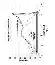
FIG. 4 is a chart showing water loss versus flue gas temperature.
DETAILED DESCRIPTION OF THE INVENTION
As shown in FIG. 1, during a typical steam power plant Rankin cycle, the condensed steam is pressurized by a pump from 1 to 2, the water is then boiled to become steam again from 2 to 3, and the steam expands through the turbine to generate work from 3 to 4. The higher the steam turbine inlet steam temperature or the lower the steam turbine exhaust temperature or the condensing temperature, the more the work generated and thus the higher the power plant thermal cycle efficiency.
The present invention, shown generally in FIG. 2 at reference numeral 10, is an Advanced Hybrid Condenser Cooling system (AHCC) adapted for use in a steam power plant. The AHCC system 10 is a high efficiency dry cooling system designed to replace current air-cooled condenser (ACC) or wet cooling systems and eliminate the disadvantages associated with those systems by using nature to control air temperature to enhance ACC and to achieve zero water cooling for steam condensation. It should be appreciated that the system may also be used in building cooling systems.
In general, the system 10 is designed to enable steam condensate temperature at or below 30° C. in peak hours in all weather conditions, rather than at 60° C. with current air-cooled condensers (ACCs) on a hot (38° C.) day and achieves up to 10.7 percent additional power production by lowering the steam condensation temperature by 30 degrees Celsius (° C.) through the use of adsorption/absorption green chiller technologies and thermal energy storage from low nighttime temperatures. Additionally, the ability to consistently maintain a steady low steam condensation temperature and turbine back pressure throughout the year will ensure consistent power production, making the system 10 more cost effective and more broadly applicable to diverse generators (e.g. nuclear) than current ACC technologies.
The system has three unique and innovative component technologies: (1) an advanced ACC that will reduce the steam condensate temperature to 10° C. above ambient temperature; (2) a waste heat recovery system to preheat the condensed water; and (3) a peak power improvement system, composed of a solar- or waste heat-driven adsorption/absorption chiller and a thermal energy storage system, to enhance production at peak demand periods. The thermal energy storage system can also be used to balance intermittent renewable production on the grid. The system 10 enables the following benefits:
-
- Use of Thermal Energy Storage (TES) to cool air when air temperature is higher;
- Use of Vapor Absorption/Adsorption Refrigerant System (VARS) to control air temperature further after TES;
- Use of solar heat to drive VARS;
- Fully employ nature force; and
- Gain 5.35% overall efficiency.
In addition, in hot and sunny deserts, the refrigerant can release the heat to the ambient at night utilizing cold air, rather than water.
In a hot environment, TES is employed to remove heat from the air, then VARS is used to further cool the air to the desired temperature. Solar thermal energy is used to drive VARS. TES is regenerated in the night, and both TES and VARS are operated when air temperature is over the ACC desired temperature.
In more detail, as shown in FIG. 2, the system 10 utilizes TES 11, VARS 12, and a thermal energy collector 13 in combination with an ACC 14 to provide cooling to a power plant. As shown, VARS 12 is an adsorption or absorption chiller having a vacuumed evaporator 15, condenser 16, and adsorption 17 or absorption 18 chambers to reduce vapor pressure buildup, FIG. 3. In hot locations, the adsorption or absorption chambers 17, 18 can also store the vapor during the day. The vapor can be condensed at night with colder ambient air. The heat to enable de-sorption can be provided by engine exhaust air, other waste heat, or solar heat. It is a thermal driven chiller. It should be appreciated that other suitable VARS may be used.
As shown in FIG. 3, the steam from the steam turbine exhaust is condensed to water in the evaporator 15. The condensed water temperature can be as low as desirable (i.e., 40° F.) by adjusting refrigerant pressure inside the evaporator 15. The refrigerant can be water, ammonia, or other liquids. The vapor rises and flows to the left adsorbent or absorbent chamber 17. The atoms, ions, and molecules of vapor are then adhered to the surfaces of the adsorbent particles or absorbed into the absorbent. Simultaneously, the adsorbent or absorbent in the right chamber 18 is being heated up by hot air or exhaust gas to de-sorb the vapor previously adsorbed or absorbed. The vapor flows to the condenser 16 and is condensed to liquid refrigerant due to cold air. The condensed refrigerant flows back to the evaporator 15.
Unlike other commercial adsorption chillers which use a lot of cold and heated water, the chillers 12 of this invention use cold air or hot air or gas. As stated above, in hot locations, the adsorption or absorption chambers 17, 18 can also store the vapor during the day. The vapor can be condensed at night with colder ambient air. The heat to enable de-sorption can be provided by engine exhaust air, other waste heat, geothermal heat, biofuel heat, or solar heat. No pump is needed to circulate the refrigerant.
The benefits include:
-
- Reduction of steam condensing temperature with the aid of the chiller for a much higher plant cycle efficiency.
- Use of air or combination of air and water to cool the adsorbents or absorbents.
- Use of air, exhaust gas, or combination of air, steam, water, and gas, heated by the waste heat, geothermal heat, or solar heat to enable de-sorption.
- Use of adsorption or absorption to store the refrigerant vapor during the hot daytime and to condense the vapor with the colder air at night.
- Evaporative cooling provides hundreds of times higher heat removal rate than convective water cooling.
- Reduced FGD water loss by as high as 50%.
The chiller of the present invention would use 50 to 100% less water than the commercial adsorption or absorption chillers or the water cooled condensers, and can improve cycle efficiency by 20%. As shown in FIG. 4, reducing flue gas temperature can result in up to 50% less FGD water loss.
The collector 13 is an evacuated tube solar thermal energy collector because it can achieve high temperatures and has an efficiency rating of up to 85 percent. It should be appreciated that other suitable types of collectors may be used. The TES 11 uses a salt hydrate for the TES material. The salt hydrate is preferably a lithium nitrate trihydrate (LiNO3-3H2O): ΔHfus=295 J/g and ˜400 MJ/m3 by additives because it is a neutral salt which is compatible with aluminum.
The ACC 14 is a cross-flow heat exchanger aimed at minimizing the difference between the condensate temperature and the entrance air temperature to 10° C., rather than 22° C. to 30° C. for current ACCs, without penalizing the pressure drop significantly. This is achieved by using a 44.8% larger air-side heat transfer area by using mini-channel flat tubes, instead of the current large size flat tubes, and denser and taller fins. The taller fins allow an increased cross-section of air-side flow channel between the fins to keep the same pressure drop, even with narrower flow channels due to denser fins. Furthermore, the wall thicknesses have been reduced to decrease wall thermal resistance by 33% and weight. The steam flow channel and fin sizes have been further optimized to maximize both steam and airflow channels for minimized pressure drop impacts on both sides. To minimize condensate film and to prevent from flooding, which significantly hinders condensate efficiency resulting in larger ACCs, condensate drains have been added along the steam flow path.
Unlike a standard ACC, the system 10 uses the TES 11 and VARS 12 to control air temperature when air temperature is over 20° C. Thus, the power plant steam condensate temperature can be controlled under 38° C. instead of the current 60° C., thereby, increasing overall plant efficiency.
Since air cooled thermal driven VARS 12 refrigerant efficiency is impacted by air temperature over 35° C., TES 11 is used to remove heat from the air to provide air having a temperature lower then 35° C. There are three ambient air temperature cases that effect the operation of the system 10. The first is when the ambient air temperature T>35° C. In this case, the ambient air is pre-cooled in TES 11 down to 35° C. and is then separated into two flows. The first flow is used to cool VARS 12 and the second flow is further cooled by VARS until the air temperature is down to 20° C. After these two steps, the cold stream of air is then directed to the ACC 14 inlet. The VARS 12 is driven by solar heat from the collector 13. The second case is when the ambient air temperature T is 20° C.<T≦35° C., the ambient air can be used to cool VARS 12 directly but not ACC 14. Therefore, the air will be cooled by VARS 12 until its temperature is down to 20° C. After the temperature reaches 20° C., the cold stream is then directed to the ACC 14 inlet. The VARS 12 is driven by solar heat from the collector 13. The third case is when the ambient air temperature T≦20° C. In this case, the ambient air can be used for ACC 14 directly without additional cooling from the TES 11 and VARS 12.
Using the table in FIG. 2, a more detailed explanation of the operation of system 10 can be described.
Case No. 1
If the ambient air at point A is 40° C., it is cooled slightly from point B to point D and preheats the condensed 30° C. water through a heat exchanger 20 to minimize fuel consumption. The air is further cooled to 35° C. from point E to point F through the TES 11. From point I to point J, the air is cooled additionally by the VARS 12 to 20° C. before picking up heat from condensing the steam in the ACC 14. Part of the 26° C. air from the ACC 14 flows through the VARS 12 condenser to condense the refrigerant inside the VARS 12. The rest of the 26° C. air flows into the adsorption/absorption chamber 17, 18 of the VARS 12 to remove the heat built up due to adsorption/absorption. The 49.82° C. air at point o is partially injected into the furnace inside boiler 21 and mixed with the fuel to enhance combustion and reduce fuel consumption.
Case No. 2
If the ambient temperature is greater than 20° C. but less than 35° C., the ambient air flows from point A to points C, D, G, H, and I and is pre-cooled by the VARS 12 only, without going through the TES 11. The rest of the flow is the same as that for 40° C. air.
Case No. 3
If the ambient temperature is less than 20° C. or at nighttime, the ACC 14 is cooled by the ambient air directly, without the TES 11 and VARS 12. The heated 25° C. air at point M is partially injected into the furnace inside the boiler 21 to minimize fuel consumption. The adsorption/absorption chamber 17, 18 and refrigerant condenser 16 at the top of the VARS 12 are cooled by ambient cold air of less than 20° C.
It should be appreciated that the system 10 only employs the VARS 12 to control air temperature when it is hot; and only employs the TES 11 in really hot conditions. It should also be appreciated that the collector 13 collects solar thermal energy for VARS 12 regeneration and that the TES 11 is regenerated at night.
As shown below, the system 10 drops the steam condensing temperature to 30° C. as compared with a standard ACC's 60° C. to provide a power plant overall efficiency increase of up to 4 percent. Table 1 shows the overall power plant efficiency under different condensate temperatures.
| TABLE 1 | |||
| Condensate | 60° C.(140° F.) | 30° C. (86° F.) | 20° C. (68° F.) |
| Temperature | |||
| Condenser | 19.9 kPa | 4.24 kPa | 2.34 kPa |
| Pressure | (5.9 inHg) | (1.25 inHg) | (0.69 inHg) |
| ST net heat rate | 8101 kJ | 7464 kJ | 7272 kJ |
| (7679 Btu)/kWh | (7075 Btu)/kWh | (6893 Btu)/kWh | |
| ST net | 44.44% | 48.23% | 49.50% |
| efficiency | |||
Table 2 shows base plant parameters for a 500MW power plant.
| TABLE 2 | ||||
| Steam | Cooling system | Steam condenser | ||
| Capacity | flow | heat load | temperature | |
| Type | (MWe) | (kg/s) | (MW) | (° C.) |
| Coal fired | 500 | 314 | 732 | 30 |
| steam power | ||||
| plant | ||||
Table 3 shows VARS parameters working under ideal conditions with a COP=1.7.
| TABLE 3 | ||||||||||
| Total | Total | VARS | ||||||||
| VARS | regeneration | reject | request | Air | 11MW | |||||
| Refrigeration | thermal | waste | Evaporate | Regeneration | cooling | Cooling air | temp. | Air mass | VARS unit | |
| capacity | energy | heat | temp. | temp. | temp. | initial temp. | rise | flow rate | price | Total cost |
| MW | MW | MW | ° C. | ° C. | ° C. | ° C. | ° C. | kg/s | $ | $ |
| 1046 | 615 | 1661 | 5 | 150 | 50 | 35 | 10 | 1.60 × 10⁵ | 4.29 × 10⁵ | 4.07 × 10⁷ |
Assuming the ambient air temperature is Tair ambient=40° C., The base TES 11 parameters are listed in Table 4.
| TABLE 4 | ||||||||
| Air | ||||||||
| mass | ||||||||
| flow | ||||||||
| rate | ||||||||
| (For | Total | |||||||
| Ambient air | TES | Controlled | VARS | thermal | Total | |||
| day time | working | air | and | energy of | Mass of | Volume of | Price of | cost |
| temperature | hours | temperature | ACC) | TES | LiNO3 | LiNO3 | LiNO3 | dollars |
| ° C. | hrs | ° C. | kg/s | MJ | Ton | m3 | $/Ton | $ |
| 40 | 6 | 35 | 2.6 × 10⁵ | 2.92 × 10⁷ | 9.91 × 10⁴ | 7.31 × 10⁷ | 500 | 4.95 × 10⁷ |
Assuming the ACC inlet air temperature is controlled at Tinitial=20° C., The base ACC parameters are listed in Table 5.
| TABLE 5 | |||||||
| ACC inlet | ACC outlet | Steam | |||||
| air | air | Air mass | condenser | Number | assumed | ACC | |
| temperature | temperature | LMTD | flow rate | temperature | of cells | cell price | cost |
| ° C. | ° C. | ° C. | kg/s | ° C. | # | $/cell | $ |
| 20 | 27 | 5.8 | 1.01 × 10⁵ | 30 | 60 | 1.5 × 10⁶ | 9 × 10⁷ |
The base evacuated tube solar thermal energy collector parameters are listed in Table 6.
| TABLE 6 | ||||||
| Total heat for | ||||||
| VARS | ||||||
| regeneration | Collector | Standard tube | ||||
| based on VARS | working | Standardized | section area | Number of | The year | |
| COP = 1.7 | Temp. | solar energy | φ0.058 m × 1.8 m | tubes | Price | gain |
| MW | ° C. | kW/m2 | m2 | # | $/tube | $ |
| 615 | 150 | 1.4 | 0.1044 | 4.95 × 10⁶ | 12 | 5.94 × 10⁷ |
The overall efficiency is increased 5.35% by reducing condenser temperature from 60° C. to 30° C. Compared with ACC 14 alone, the gain per year is listed in Table 7.
| TABLE 7 |
| Estimated efficiency, power production, and income gains due to GCC |
| compared with current ACC 500MW steam power plant* |
| Annual | ||||||
| Annual | Average | Annual | ||||
| Average | Condensate | Average | Annual | Electricity | ||
| Condensate | Temperature | Power | Power | Wholesale | Annual | |
| Temperature | with Current | Annual Average | Production | Production | Price | Additional |
| with GCC | ACC | Efficiency Gain | Gain | Gain | Assumptions | Income* |
| 30° C. | 45° C. | 5.35% | 26.75MW | 234.3 GWh | $0.08/kWh | US$18.75 |
| Million | ||||||
The foregoing has described a system and method of using adsorption or absorption technologies for thermal-electric power plant cooling. While specific embodiments of the present invention have been described, it will be apparent to those skilled in the art that various modifications thereto can be made without departing from the spirit and scope of the invention. Accordingly, the foregoing description of the preferred embodiment of the invention and the best mode for practicing the invention are provided for the purpose of illustration only and not for the purpose of limitation.
Claims
We claim:1. A hybrid cooling system adapted to provide cooling to a thermal-electric power plant, comprising:
(a) an air-cooled condenser (ACC) adapted to provide cooling water to the thermal-electric power plant; and
(b) a vapor absorption/adsorption refrigerant system (VARS) adapted to provide cooled air to the ACC, wherein the cooled air is used by the ACC to condense steam to produce the cooling water.
2. The system according to claim 1, further including a thermal energy storage (TES) system adapted to receive and store cooling air.
3. The system according to claim 2, wherein the TES removes heat from the cooling air.
4. The system according to claim 1, further including a thermal energy collector adapted to collect heat energy and provide the heat energy to the VARS to enable de-sorption.
5. The system according to claim 1, wherein the VARS includes:
(a) an evaporator adapted to condense steam to water;
(b) a first adsorbent or absorbent chamber to absorb refrigerant vapor used in the evaporator to condense the steam;
(c) a second adsorbent or absorbent chamber to de-sorb the vapor absorbed in the first chamber; and
(d) a condenser adapted to condense the vapor to a liquid refrigerant, wherein the liquid refrigerant flows back to the evaporator to condense more steam.
6. The system according to claim 1, further including a heat exchanger adapted to pre-heat condensed water using ambient air.
7. The system according to claim 1, further including:
(a) a heat exchanger adapted to pre-heat condensed water from the ACC using ambient air; and
(b) a thermal energy storage system (TES) adapted to receive ambient air, cool the ambient air, and store the cooled ambient air to provide cooling air to the VARS for additional cooling.
8. A method of using adsorption/absorption to provide cooling to a thermal-electric power plant, comprising the steps of:
(a) providing a hybrid cooling system, including:
(i) an air-cooled condenser (ACC); and
(ii) a vapor absorption/adsorption refrigerant system (VARS);
(b) using the VARS to cool air and provide the cooled air to the ACC;
(c) using the cooled air in the ACC to condense steam from a steam turbine to cooling water; and
(d) providing the cooling water from the ACC to a boiler of the thermal-electric power plant.
9. The method according to claim 8, wherein the cooled air is heated in the ACC when the steam is condensed to cooling water;
10. The method according to claim 8, further including the step of providing cooled air from the ACC to an adsorption/absorption chamber of the VARS to remove heat from the chamber and provide heated air.
11. The method according to claim 10, further including the step of injecting the heated air into a furnace of the boiler to enhance combustion.
12. The method according to claim 8, further including the step of providing a thermal energy storage system (TES), wherein the TES is adapted to receive ambient air, cool the ambient air, and store the cooled ambient air to provide the cooled ambient air to the VARS for additional cooling.
13. The method according to claim 8, further including a heat exchanger adapted to pre-heat the cooling water from the ACC.
14. The method according to claim 8, further including a thermal energy collector adapted to collect heat energy and provide the heat energy to the VARS to enable de-sorption.
Images & Drawings included:


Sources:
- United States Patent and Trademark Office - verify current appl. status at the USPTO↗
Recent applications in this class:
- » 20190331368 2019-10-31
HEAT STORAGE MATERIAL, METHOD FOR PRODUCTION OF HEAT STORAGE MATERIAL, AND CHEMICAL HEAT PUMP - » 20170299234 2017-10-19
Method of bringing to temperature and holding at temperature the interior of a thermally insulated enclosure with no continuous supply of energy and the associated device - » 20150176869 2015-06-25
Intermittent absorption refrigeration system equipped with a waste energy storage unit - » 20150159923 2015-06-11
Adsorption refrigerator - » 20150143827 2015-05-28
Economizer for an intermittent absorption refrigeration system - » 20150121916 2015-05-07
Enclosure refrigerated by a hybrid compression/absorption refrigeration system - » 20140298832 2014-10-09
Method for operating a cyclical thermal adsorption heating or refrigeration system, and device - » 20140130540 2014-05-15
Adsorber structure and module for a heat pump - » 20130276475 2013-10-24
Adsorber and adsorption heat pump - » 20110214449 2011-09-08
REFRIGERATOR
Recent applications for this Assignee:
- » 20220184728 2022-06-16
Method to eliminate dissimilar metal welds - » 20210396033 2021-12-23
Emergency restoration system and method - » 20210348415 2021-11-11
Emergency restoration system and method - » 20210141027 2021-05-13
Method of determining battery degradation - » 20190154750 2019-05-23
Sensor to monitor health of metal oxide arresters - » 20190074671 2019-03-07
Method of replacing pipe-type power cables with extruded-dielectric cables - » 20190019589 2019-01-17
Apparatus and method for identifying cracks in a structure using a multi-stage classifier - » 20180102042 2018-04-12
Apparatus and method for identifying ballistic impact to power transmission assets - » 20180017610 2018-01-18
Sensor to monitor health of metal oxide arresters - » 20180016945 2018-01-18
Reheating of a working fluid within a turbine system for power generation