Signalling report transmission in carrier aggregation
US20130128829A1
2013-05-23
13/640,055
2010-04-09
✅ Patent granted
US 10,667,241 B2
2020-05-26
WO; PCT/EP2010/054699; 20100409
WO; WO2011/124263; 20111013
Kevin M Cunningham
Harrington & Smith
2030-05-14
Abstract:
A user equipment prepares a signalling report in response to receiving a control element for activation/deactivation of component carriers to be used by the user equipment for communication in a cellular communications network system, and transmits the signalling report.
Assignee:
- NOKIA SIEMENS NETWORKS OY 1,029 🇫🇮 Espoo, Finland
- Nokia Solutions and Networks Oy 2,409 🇫🇮 Espoo, Finland
Applicant:
Interested in similar patents?
Get notified when new applications in this technology area are published.
Classification:
H04L5/001 » CPC further
Arrangements affording multiple use of the transmission path; Arrangements for dividing the transmission path; Two-dimensional division; Time-frequency the frequencies being orthogonal, e.g. OFDM(A), DMT the frequencies being arranged in component carriers
H04L5/0098 » CPC further
Arrangements affording multiple use of the transmission path; Signaling for the administration of the divided path; Indication of changes in allocation Signalling of the activation or deactivation of component carriers, subcarriers or frequency bands
H04W72/1284 » CPC further
Local resource management, e.g. wireless traffic scheduling or selection or allocation of wireless resources; Wireless traffic scheduling; Transmission of control information for scheduling in the uplink, i.e. from terminal to network
H04W52/365 » CPC further
Power management, e.g. TPC [Transmission Power Control], power saving or power classes; TPC using constraints in the total amount of available transmission power with a discrete range or set of values, e.g. step size, ramping or offsets Power headroom reporting
H04W72/12 IPC
Local resource management, e.g. wireless traffic scheduling or selection or allocation of wireless resources Wireless traffic scheduling
H04W52/36 IPC
Power management, e.g. TPC [Transmission Power Control], power saving or power classes; TPC using constraints in the total amount of available transmission power with a discrete range or set of values, e.g. step size, ramping or offsets
H04L5/00 IPC
Arrangements affording multiple use of the transmission path
H04W72/04 » CPC main
Local resource management, e.g. wireless traffic scheduling or selection or allocation of wireless resources Wireless resource allocation
Description
The present invention relates to a signalling report transmission in carrier aggregation. In particular, the present invention relates to a buffer status and power headroom reports transmission in carrier aggregation.
Among signalling reports standardized in Release 8 of E-UTRAN (evolved universal terrestrial radio access network) to support uplink packet scheduling and link adaptation are a buffer status report (BSR) and a power headroom report (PHR). BSR is used to inform an eNB (evolved node B) of an amount of data available for transmission in a UE (user equipment) buffer. A PHR brings information on how close the UE is operating to its maximum transmission power capabilities, and is therefore important for the eNB to be able to estimate an experienced SINR (signal to interference-plus-noise ratio) when the UE is allocated a certain transmission bandwidth. A BSR is typically used by the eNB to choose an appropriate transport block size while a PHR is typically used to select an appropriate modulation and coding scheme (MCS).
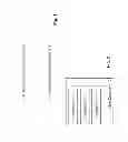
Release 10 of E-UTRAN introduces carrier aggregation (CA), where two or more component carriers (CCs) are aggregated in order to support wider transmission bandwidths up to 100 MHz and for spectrum aggregation. In CA, it is possible to configure a UE to aggregate a different number of CCs originating from the same eNB and of possibly different bandwidths in UL (uplink) and DL (downlink). The principle of carrier aggregation is illustrated in FIG. 1 which shows an LTE (long term evolution) advanced system bandwidth comprising 5×20 MHz component carriers. 3GPP (third generation partnership project) Release 8 UEs are assumed to be served by a stand-alone CC, while Release 10 terminals can be configured to receive or transmit simultaneously on multiple aggregated CCs in the same TTI (transmission time interval).
In CA, component carriers that are configured for a UE can be activated/deactivated dynamically by means of a MAC (medium access control) control element. For an eNB to obtain an updated knowledge of buffer status and power headroom of the UE when activation/deactivation of CCs takes place, the eNB has to force an RRC (radio resource control) connection reconfiguration of PHR reporting. The reconfiguration of the PHR reporting is a straightforward trigger for PHR but also an indirect one for BSR as it triggers an RRC response in uplink, which is considered as high priority data arrival and therefore triggers a BSR.
That is, a BSR is triggered upon 1) arrival of high priority data, 2) periodic reporting, or 3) occurrence of padding large enough to accommodate a BSR. A PHR is triggered upon 1) path loss change, 2) periodic reporting or 3) reconfiguration of the reporting.
The present invention aims at immediately providing an eNB with updated knowledge of buffer status and power headroom of a UE when activation/deactivation of CCs takes place.
This is achieved by an apparatus, method and computer program product as defined in the appended claims.
According to an embodiment of the invention, a user equipment prepares a signalling report in response to receiving a control element for activation/deactivation of component carriers to be used by the user equipment for communication in a cellular communications network system, and transmits the signalling report.
Thus, an eNB can be provided with signalling reports from a UE when activation/deactivation of CCs takes place without having to perform an RRC connection reconfiguration.
In the following the invention will be described by way of embodiments thereof with reference to the accompanying drawings, in which:
FIG. 1 shows a basic illustration of component carriers to form LTE-Advanced system bandwidth;
FIG. 2 shows a schematic block diagram illustrating a structure of a UE according to an embodiment of the invention; and
FIG. 3 shows a signalling diagram illustrating signalling between a UE, an eNB and an E-UTRAN according to an embodiment of the invention.
Referring to FIG. 2, a user equipment (UE) 10 comprises a processor 11, a memory 12 and a transceiver 13 which are connected via a bus 14. The UE 10 may be compliant with Release 10 of E-UTRAN.
The memory 12 may store a program, and the transceiver 13 may be a suitable radio frequency (RF) transceiver coupled to one or more antennas (not shown) for bidirectional wireless communications over one or more wireless links with an eNB.
The terms “connected,” “coupled,” or any variant thereof, mean any connection or coupling, either direct or indirect, between two or more elements, and may encompass the presence of one or more intermediate elements between two elements that are “connected” or “coupled” together. The coupling or connection between the elements can be physical, logical, or a combination thereof. As employed herein two elements may be considered to be “connected” or “coupled” together by the use of one or more wires, cables and printed electrical connections, as well as by the use of electromagnetic energy, such as electromagnetic energy having wavelengths in the radio frequency region, the microwave region and the optical (both visible and invisible) region, as non-limiting examples.
The program stored in the memory 12 may include program instructions that, when executed by the processor 11, enable the UE 10 to operate in accordance with the exemplary embodiments of this invention, as detailed below. Inherent in the processor 11 is a clock to enable synchronism among the various apparatus for transmissions and receptions within the appropriate time intervals and slots required, as the scheduling grants and the granted resources/subframes are time dependent. The transceiver 13 includes both transmitter and receiver, and inherent in each is a modulator/demodulator commonly known as a modem.
In general, the exemplary embodiments of this invention may be implemented by computer software stored in the memory 12 and executable by the processor 11 of the UE 10, or by hardware, or by a combination of software and/or firmware and hardware in any or all of the devices shown.
In general, the various embodiments of the UE 10 can include, but are not limited to, mobile stations, cellular telephones, personal digital assistants (PDAs) having wireless communication capabilities, portable computers having wireless communication capabilities, image capture devices such as digital cameras having wireless communication capabilities, gaming devices having wireless communication capabilities, music storage and playback appliances having wireless communication capabilities, Internet appliances permitting wireless Internet access and browsing, as well as portable units or terminals that incorporate combinations of such functions.
The memory 12 may be of any type suitable to the local technical environment and may be implemented using any suitable data storage technology, such as semiconductor-based memory devices, magnetic memory devices and systems, optical memory devices and systems, fixed memory and removable memory. The processor 11 may be of any type suitable to the local technical environment, and may include one or more of general purpose computers, special purpose computers, microprocessors, digital signal processors (DSPs) and processors based on a multi-core processor architecture, as non-limiting examples.
Embodiments of the invention may be practiced in various components such as integrated circuit modules. The design of integrated circuits is by and large a highly automated process. Complex and powerful software tools are available for converting a logic level design into a semiconductor circuit design ready to be etched and formed on a semiconductor substrate.
Programs, such as those provided by Synopsys, Inc. of Mountain View, Calif. and Cadence Design, of San Jose, Calif. automatically route conductors and locate components on a semiconductor chip using well established rules of design as well as libraries of pre-stored design modules. Once the design for a semiconductor circuit has been completed, the resultant design, in a standardized electronic format (e.g., Opus, GDSII, or the like) may be transmitted to a semiconductor fabrication facility or “fab” for fabrication.
According to an embodiment of the invention, the processor 11 of the UE 10 prepares a signalling report in response to receiving a control element for activation/deactivation of component carriers to be used by the UE 10 for communication in a cellular communications network system, and the transceiver 13 transmits the signalling report. The UE 10 may receive the control element for activation/de-activation via the transceiver 13 from an E-UTRAN, e.g. from an eNB of the E-UTRAN with which the UE 10 communicates currently. The transceiver 13 may transmit the signalling report to an eNB with which the UE 10 communicates currently.
The signalling report transmitted by the transceiver 13 may support uplink packet scheduling and link adaptation for the UE 10. The signalling report may include a buffer status report and/or a power headroom report.
The control element for activation/deactivation may be a medium access control element and may comply with a MAC protocol. The transceiver 13 may transmit the signalling report via a medium access control element complying with the MAC protocol.
The control element for activation/deactivation may be a control element for activation of component carriers and/or a control element for deactivation of component carriers. The component carriers may comprise at least one of component carriers configured to be used by the UE 10.
Thus, according to an embodiment of the invention, a new trigger is introduced for PHR and BSR: activation/de-activation of CC. Since activation/deactivation of CC is performed by a MAC control element, the new trigger can also be described as reception of a MAC control element for activation/deactivation. The trigger may be restricted to activation only and therefore exclude de-activation. It is also possible to restrict the trigger further to a subset of configured CCs. Such restrictions may be different for BSR and PHR. For instance, a PHR may be triggered upon activation and deactivation of any CC, i.e. upon reception of a MAC control element for activation/deactivation, while a BSR may be triggered upon activation only.
FIG. 3 shows a signalling diagram illustrating signalling between the UE 10, an eNB 20 and an E-UTRAN 30 according to an embodiment of the invention.
In a step 1 the UE 10 receives a control element for activation/deactivation of component carriers to be used by the UE 10 for communication in a cellular communications network system. According to the embodiment shown in FIG. 3, the cellular communications system comprises the E-UTRAN 30. The UE 10 may receive the control element for activation/deactivation from the E-UTRAN 30, e.g. the eNB 20 with which the UE 10 currently communicates. According to the embodiment shown in FIG. 3, the control element for activation/deactivation is a medium access control element.
Upon receiving the control element, in a step 2 the UE 10 prepares a signalling report. The signalling report may support uplink packet scheduling and link adaptation for the UE 10 by the eNB 20. According to the embodiment shown in FIG. 3, the signalling report includes BS/PH reports.
In a step 3, the UE 10 transmits the BS/PH reports to the eNB 20. According to the embodiment shown in FIG. 3, the BS/PH reports are transmitted via a medium access control element.
As mentioned above, the control element for activation/deactivation may comprise a control element for activation of component carriers and/or a control element for deactivation of component carriers, and the component carriers may comprise at least one of component carriers configured to be used by the UE 10. There may be different triggers for BSR and PHR, e.g. a PHR may be prepared and transmitted by the UE 10 upon receiving a MAC control element for activation and/or deactivation of any CC, while the UE 10 prepares and transmits a BSR upon receiving a MAC control element for activation only. The trigger may further be restricted to a subset of configured CCs.
According to an aspect of the present invention, an apparatus such as the UE 10 comprises preparing means for preparing a signalling report in response to receiving a control element for activation/deactivation of component carriers to be used by the apparatus for communication in a cellular communications network system, and transmitting means for transmitting the signalling report. The preparing means may comprise the processor 11, and the transmitting means may comprise the transceiver 13.
The signalling report may support uplink packet scheduling and link adaptation for the apparatus and/or include a buffer status report and/or a power headroom report.
The control element for activation/deactivation may be a medium access control element and/or the transmitting means may transmit the signalling report via a medium access control element.
The control element for activation/deactivation may comprise at least one of the following group: a control element for activation of component carriers and a control element for deactivation of component carriers, and the component carriers may comprise at least one of component carriers configured to be used by the apparatus.
It is to be understood that the above description is illustrative of the invention and is not to be construed as limiting the invention. Various modifications and applications may occur to those skilled in the art without departing from the true spirit and scope of the invention as defined by the appended claims.
Claims
1. An apparatus comprising:
a processor configured to prepare a signalling report in response to receiving a control element for activation/deactivation of component carriers to be used by the apparatus for communication in a cellular communications network system; and
a transceiver configured to transmit the signalling report .
2. The apparatus of claim 1, wherein the signalling report supports uplink packet scheduling and link adaptation for the apparatus and/or includes a buffer status report and/or a power headroom report.
3. The apparatus of claim 1, wherein the control element for activation/deactivation is a medium access control element and/or the transceiver is configured to transmit the signalling report via a medium access control element.
4. The apparatus of claim 1, wherein the control element for activation/deactivation comprises at least one of the following group: a control element for activation of component carriers and a control element for deactivation of component carriers, and wherein the component carriers comprise at least one of component carriers configured to be used by the apparatus.
5. A method comprising:
preparing a signalling report in response to receiving a control element for activation/deactivation of component carriers to be used by an apparatus for communication in a cellular communications network system; and
transmitting the signalling report.
6. The method of claim 5, wherein the signalling report supports uplink packet scheduling and link adaptation for the apparatus and/or includes a buffer status report and/or a power headroom report.
7. The method of claim 5, wherein the control element for activation/deactivation is a medium access control element and/or the transmitting comprises transmitting the signalling report via a medium access control element.
8. The method of claim 5, wherein the control element for activation/deactivation comprises at least one of the following group: a control element for activation of component carriers and a control element for deactivation of component carriers, and wherein the component carriers comprise at least one of component carriers configured to be used by the apparatus.
9. A computer program product including a program for a processor, comprising software code portions for performing the steps of claim 5 when the program is run on the processor.
10. The computer program product according to claim 9, wherein the computer program product comprises a computer-readable medium on which the software code portions are stored.
11. The computer program product according to claim 9, wherein the program is directly loadable into an internal memory of the processor.
Images & Drawings included:


Sources:
- United States Patent and Trademark Office - verify current appl. status at the USPTO↗
Recent applications in this class:
- » 20250294529 2025-09-18
V2X DYNAMIC GROUPCAST RESOURCE ALLOCATION - » 20250280395 2025-09-04
RESOURCE SELECTION FOR MULTIPLE COORDINATION MESSAGES - » 20250280394 2025-09-04
NETWORK SLICE SMART ALLOCATION CONTROL SYSTEM - » 20250234338 2025-07-17
RESOURCE DELIVERY FOR PEER TO PEER GROUP - » 20250227667 2025-07-10
TECHNIQUE FOR ALLOCATING RESOURCE UNIT IN WIRELESS COMMUNICATION SYSTEM - » 20250227666 2025-07-10
RESOURCE SOLICITATION FOR PEER TO PEER GROUP - » 20250227665 2025-07-10
DYNAMIC NETWORK SLICING - » 20250212184 2025-06-26
RESOURCE SELECTION METHOD AND APPARATUS, AND TERMINAL - » 20250212183 2025-06-26
Network Device and Method for Handling Downlink Multi-user Multiplexing for a Wireless Local Area Network - » 20250212182 2025-06-26
RESOURCE ALLOCATION FOR USER EQUIPMENT PAIRED PROCESSING
Recent applications for this Assignee:
- » 20250294462 2025-09-18
DISTORTION REDUCING PRECODING - » 20250279947 2025-09-04
NETWORK- AND COMPUTE-AWARE SERVICE CONTACT POINT SELECTION - » 20250279875 2025-09-04
PHASE ESTIMATION FOR CLOCK-AND-DATA RECOVERY INITIALISATION IN AN OPTICAL RECEIVER OF A PASSIVE OPTICAL NETWORK - » 20250274393 2025-08-28
RESOURCE SHARING AMONG NETWORK GATEWAYS IN SOFTWARE-DEFINED NETWORKS - » 20250274376 2025-08-28
MULTI-THREADED SIMULATOR FOR PERFORMANCE BENCHMARKING IN SOFTWARE-DEFINED NETWORKS - » 20250267381 2025-08-21
METHOD AND APPARATUS FOR WAKING UP AN ONU - » 20250267125 2025-08-21
EFFICIENT, RESOURCE-AWARE SECURITY OPERATIONS IN SOFTWARE-DEFINED NETWORKS - » 20250261169 2025-08-14
COMMUNICATION DEVICE, METHOD, APPARATUS, AND COMPUTER READABLE STORAGE MEDIUM - » 20250260647 2025-08-14
CACHE-ASSISTED SERVICE CONTACT INSTANCE SELECTION FOR COMPUTING-AWARE TRAFFIC STEERING NETWORKS - » 20250254594 2025-08-07
Mobile Terminal Handover Decision Optimizations