Household appliance including force distributor
US20130134847A1
2013-05-30
13/305,781
2011-11-29
✅ Patent granted
US 8,915,559 B2
2014-12-23
-
-
Daniel Rohroff
James E. Howard | Andre Pallapies
2031-11-29
Abstract:
A household appliance including a cabinet having a frame and one or more force distributors structured to absorb forces that the cabinet receives during shipping and handling. The one or more force distributors may include a block portion having cut-out sections throughout that lead to a generally flat planar bottom portion. To reduce material costs, the cut-out sections may include a surface area of greater than fifty percent of the total surface area of the one or more force distributors. The invention also includes a method for attaching the one or more force distributors to the household appliance.
Inventors:
- Louis Kinlaw 1 🇺🇸 Greenville, NC, United States
- Rob Ladner 2 🇺🇸 Dryden, MI, United States
Assignee:
- BSH HOME APPLIANCES CORPORATION 104 🇺🇸 Huntington Beach, CA, United States
- BSH HOME APPLIANCES CORPORATION 261 🇺🇸 Irvine, CA, United States
Applicant:
Interested in similar patents?
Get notified when new applications in this technology area are published.
Classification:
B65D81/02 » CPC main
Containers, packaging elements, or packages, for contents presenting particular transport or storage problems, or adapted to be used for non-packaging purposes after removal of contents specially adapted to protect contents from mechanical damage
B65D81/053 » CPC further
Containers, packaging elements, or packages, for contents presenting particular transport or storage problems, or adapted to be used for non-packaging purposes after removal of contents specially adapted to protect contents from mechanical damage maintaining contents at spaced relation from package walls, or from other contents Corner, edge or end protectors
A47L15/4268 » CPC further
Washing or rinsing machines for crockery or tableware; Details; Details of the casing Arrangements for transporting or moving, e.g. stiffening
B65D2581/055 » CPC further
Containers, packaging elements, or packages, for contents presenting particular transport or storage problems, or adapted to be used for non-packaging purposes after removal of contents specially adapted to protect contents from mechanical damage maintaining contents at spaced relation from package walls, or from other contents; Details of packaging elements for maintaining contents at spaced relation from package walls, or from other contents; Materials Plastic in general, e.g. foamed plastic, molded plastic, extruded plastic
B65D2585/6815 » CPC further
Containers, packaging elements or packages specially adapted for particular articles or materials for machines, engines, or vehicles in assembled or dismantled form specific machines, engines or vehicles kitchen devices, including unspecified devices, e.g. Haushaltgeräte
B65D2585/6855 » CPC further
Containers, packaging elements or packages specially adapted for particular articles or materials for machines, engines, or vehicles in assembled or dismantled form specific machines, engines or vehicles other household devices washing machine
D06F39/001 » CPC further
Details of washing machines not specific to a single type of machines covered by groups - Arrangements for transporting, moving, or setting washing machines; Protective arrangements for use during transport
Y10T29/49826 » CPC further
Metal working; Method of mechanical manufacture Assembling or joining
A47B97/00 IPC
Furniture or accessories for furniture, not provided for in other groups of this subclass
A47B96/00 IPC
Details of cabinets, racks or shelf units not covered by a single one of groups - ; General details of furniture
B23P17/04 IPC
Metal-working operations, not covered by a single other subclass or another group in this subclass characterised by the nature of the material involved or the kind of product independently of its shape
A47B77/06 IPC
Kitchen cabinets; Provision for particular uses of compartments or other parts ; Compartments moving up and down, revolving parts for incorporating sinks, with or without draining boards, splash-backs, or the like
Description
BACKGROUND OF THE INVENTION
1. Field of the Invention
The present invention relates to a household appliance and more particularly, to a household appliance including one or more force distributors and a method thereof that is used to absorb forces during shipping and handling of the dishwasher.
2. Related Art
In the related art, household appliances, such as dishwashers, include mechanisms such as packaging and force distributors that are used to protect the household appliance during shipping and handling. However, in the related art, the force distributors often require the use of screws to attach them to the dishwasher. Further, the force distributors are often costly to produce, in part due to material costs.
The present invention introduces a household appliance with one of more force distributors that use up to fifty percent less material than related art force distributors and also eliminate the need for attachment screws. In exemplary embodiments of the invention, the force distributors use snap-fit mechanisms as well as press-fit mechanisms to attach the force distributors to a frame of the dishwasher.
SUMMARY OF THE INVENTION
A first aspect of the present invention is directed to a household appliance. The household appliance may include a cabinet having a frame and one or more force distributors structured to absorb forces that the cabinet receives during shipping and handling. The one or more force distributors may include a block portion having cut-out sections throughout that lead to a generally flat planar bottom portion. To reduce material costs, the cut-out sections may include a surface area of greater than fifty percent of the total surface area of the one or more force distributors.
A second aspect of the present invention is directed to a method for absorbing forces that a cabinet of a household appliance receives during shipping and handling. The method may include attaching one or more force distributors to a frame of the household appliance, the one or more force distributors including a block portion having cut-out sections throughout that lead to a generally flat planar bottom portion. Further, the one or more force distributors may be formed from injection molding.
The illustrative aspects of the present invention are designed to solve the problems herein described and other problems not discussed.
BRIEF DESCRIPTION OF THE DRAWINGS
These and other features of this disclosure will be more readily understood from the following detailed description of the various aspects of the disclosure taken in conjunction with the accompanying drawings that depict various exemplary embodiments of the disclosure, in which:
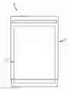
FIG. 1 depicts a household appliance including a frame according to an exemplary embodiment of the invention;
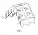
FIG. 2 depicts a force distributor structured to absorb forces that a cabinet of the household appliance receives during shipping and handling;
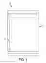
FIG. 3 depicts a front portion of the frame including a cut-out section to which the force distributor is attached according to an exemplary embodiment of the invention;
FIG. 4 depicts a second embodiment of a force distributor of the invention structured to absorb forces that the cabinet receives during shipping and handling;
FIG. 5 depicts a rear portion of the frame including a cut-out section to which the second embodiment of the force distributor is attached;
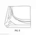
FIG. 6 depicts the force distributor of FIG. 2 formed in an approximate L-shape to attach to corners of the frame; and
FIG. 7 depicts an exemplary method of the invention for absorbing forces that a cabinet of a household appliance receives during shipping and handling.
The drawings are merely schematic representations, not intended to portray specific parameters of the invention. The drawings are intended to depict only typical embodiments of the invention, and therefore should not be considered as limiting the scope of the invention. In the drawings, like numbering represents like elements.
DETAILED DESCRIPTION OF THE INVENTION
FIG. 1 shows an exemplary embodiment of a household appliance of the present invention, such as a dishwasher 10. The dishwasher 10 may comprise a door 11 which is suitable for tiltable opening. The dishwasher may further include a frame 12 to which the door is attached and which provides for structural integrity of the dishwasher 10.
While exemplary embodiments of force distributors are described below, it should be understood that the invention is not limited to these embodiments and it is envisioned that multiple configurations of the force distributors may be used that are formed by injection molding to include up to fifty percent less material and also eliminate the need for attachment screws, for example, by using snap-fit mechanisms as well as press-fit mechanisms to attach the force distributors to a frame of the dishwasher 1.
FIG. 2 depicts an exemplary embodiment of a force distributor 20 structured to absorb forces that the cabinet receives during shipping and handling. The force distributor 20 may be attached to the frame 12 and may include a block portion 21 having cut-out sections 22 throughout that lead to a generally flat planar bottom portion 23. In FIG. 2, the force distributor 20 may include a snap-fit mechanism 24, such as a hook mechanism to attach to the frame 12.
FIG. 3 depicts a front portion of the frame 12 including a cut-out section 31 to which the force distributor 20 is attached. In the embodiment of FIG. 3, the force distributor 20 may be attached at a front corner of the frame 12.
FIG. 4 depicts a second exemplary embodiment of a force distributor 40 structured to absorb forces that the cabinet receives during shipping and handling. Like force distributor 20, force distributor 40 may be attached to the frame 12 and include a block portion 41 having cut-out sections 42 throughout that lead to a generally flat planar bottom portion 43. In FIG. 4, the force distributor 40 may include a press-fit mechanism 44 to attach to the frame 12.
FIG. 5 depicts a portion of the frame 12 including a cut-out section 51 to which the force distributor 40 is attached. In the embodiment of FIG. 5, the force distributor 40 may be attached at a rear corner of the frame 12.
The force distributors 20, 40 may be formed by injection molding from a thermoplastic material known in the art such as at least one of polystyrene, polyethylene, polypropylene, nylon, high impact polystyrene and acrylonitrile butadiene styrene (ABS).
FIG. 6 depicts the force distributor 20 formed in an approximate L-shape to attach to corners of the frame 12. As shown in FIG. 6, the force distributor 20 may include ribs 61 on a side portion thereof to reinforce a stability of the force distributor 20.
FIG. 7 depicts an exemplary method of the invention for absorbing forces that a cabinet of a household appliance receives during shipping and handling. The method includes at step 701, attaching one or more force distributors to a frame of the household appliance, the one or more force distributors including a block portion having cut-out sections throughout that lead to a generally flat planar bottom portion. In an exemplary method, the one or more force distributors may be formed from injection molding.
While only certain features of the invention have been illustrated and described herein, many modifications and changes will occur to those skilled in the art. It is, therefore, to be understood that the appended claims are intended to cover all such modifications and changes as fall within the true spirit of the invention.
Claims
1. A household appliance, comprising:
a cabinet including a frame; and
one or more force distributors structured to absorb forces that the cabinet receives during shipping and handling, the one or more force distributors attaching to the frame and including a block portion having cut-out sections throughout that lead to a generally flat planar bottom portion, wherein the cut-out sections include a surface area of greater than fifty percent of the total surface area of the one or more force distributors.
2. The household appliance according to claim 1, wherein a first of the one or more force distributors include a snap-fit mechanism to attach to the frame.
3. The household appliance according to claim 2, wherein the snap-fit mechanism is a hook mechanism.
4. The household appliance according to claim 2, wherein the frame includes a cut-out section to which the first force distributor is attached.
5. The household appliance according to claim 2, wherein the first force distributor is attached at a front corner of the frame.
6. The household appliance according to claim 1, wherein a second of the one or more force distributors includes a press-fit mechanism to attach to the frame.
7. The household appliance according to claim 6, wherein the second force distributor is disposed at a rear corner of the frame.
8. The household appliance according to claim 6, wherein the frame includes a cut-out section to which the second force distributor is attached.
9. The household appliance according to claim 1, wherein the one or more force distributors is formed from a thermoplastic material
10. The household appliance according to claim 9, wherein the thermoplastic material is at least one of polystyrene, polyethylene, polypropylene, nylon, high impact polystyrene and acrylonitrile butadiene styrene (ABS).
11. The household appliance according to claim 1, wherein the cut-out sections are formed by injection molding.
12. (canceled)
13. The household appliance according to claim 1, wherein the one or more force distributors are formed in an approximate L-shape to attach to corners of the frame
14. The household appliance according to claim 1, wherein the one or more force distributors include ribs on a side portion thereof to reinforce a stability of the one or more force distributors.
15. A method for absorbing forces that a cabinet of a household appliance receives during shipping and handling, the method comprising the step of:
attaching one or more force distributors to a frame of the household appliance, the one or more force distributors including a block portion having cut-out sections throughout that lead to a generally flat planar bottom portion, wherein the cut-out sections are formed during injection molding to include a surface area of greater than fifty percent of the total surface area of the one or more force distributors.
16. The method for absorbing forces that a cabinet of a household appliance receives during shipping and handling according to claim 15, further comprising forming the one or more force distributors from injection molding.
17. (canceled)
18. The method for absorbing forces that a cabinet of a household appliance receives during shipping and handling according to claim 15, wherein a first of the one or more force distributors is snap-fit to attach to the frame.
19. The method for absorbing forces that a cabinet of a household appliance receives during shipping and handling according to claim 15, wherein a second of the one or more force distributors is press-fit to attach to the frame.
20. The method for absorbing forces that a cabinet of a household appliance receives during shipping and handling according to claim 15, wherein during injection molding, the one or more force distributors are molded to include ribs on a side portion thereof to reinforce a stability of the one or more force distributors.
21. The method for absorbing forces that a cabinet of a household appliance receives during shipping and handling according to claim 15, wherein the frame is formed to include a cut-out section to which the one or more force distributors are attached.
Images & Drawings included:


Sources:
- United States Patent and Trademark Office - verify current appl. status at the USPTO↗
Recent applications in this class:
- » 20250171216 2025-05-29
BUFFER PACKAGING STRUCTURE AND PACKING BOX STRUCTURE - » 20250115406 2025-04-10
CORNER PROTECTOR FOR PROTECTING THE TOP CORNERS OF STACKS OF LUMBER AND CARGO - » 20240327093 2024-10-03
ENCLOSURE WITH IMPACT REDUCING FINS CONFIGURED TO PROTECT A SECOND ENCLOSURE INSIDE THE ENCLOSURE - » 20230348165 2023-11-02
Protective Transport Case for Video Monitors - » 20220194677 2022-06-23
SUPPORT BEAM FOR A TRANSPORT CONTAINER - » 20210237959 2021-08-05
CONTAINER WITH REINFORCED BOTTOM - » 20210094746 2021-04-01
Durable Container with Integrated Protection Feature - » 20200339333 2020-10-29
Blank for packaging - » 20200324955 2020-10-15
Container with reinforced bottom - » 20200299049 2020-09-24
Packaging material for prevention of rust and method of manufacturing the same
Recent applications for this Assignee:
- » 20240159451 2024-05-16
Lid assembly for controlling humidity in a refrigerator - » 20240125482 2024-04-18
Adjustable mounting system for a control panel of a home cooking appliance - » 20240110746 2024-04-04
Reducing or eliminating wobble problem in a refrigerator drawer - » 20230367275 2023-11-16
OVEN HAVING AN AUTOMATIC SELF-CLEANING SYSTEM - » 20230280091 2023-09-07
Can dispenser rack for refrigerator door - » 20230266056 2023-08-24
Multi-chambered water tank for confined spaces in a refrigeration appliance - » 20230144224 2023-05-11
Upper plinth or top panel cover for domestic appliance - » 20230094803 2023-03-30
User interface module with adjustable mount for domestic appliance - » 20220268446 2022-08-25
Home cooking appliance having an air channel - » 20220214111 2022-07-07
Household appliance including reflective door