DEVICE FOR PROTECTING OR CONTAINING SUBMERGED SURFACES, MORE PARTICULARLY THE HULLS OF VESSELS
US20130139744A1
2013-06-06
13/814,063
2011-07-28
Abstract:
A device for the containment, protection and/or treatment of a submerged surface such as a ship hull, includes a flexible and impervious or non-impervious shell, including two portions, an emerged portion (1) and a submerged portion (2) having different features.
Assignee:
- NAUTIC INNOVATION 1 🇫🇷 LOCTUDY, France
Interested in similar patents?
Get notified when new applications in this technology area are published.
Classification:
B63B59/045 » CPC main
Hull protection specially adapted for vessels; Cleaning devices specially adapted for vessels; Preventing hull fouling by wrapping the submerged hull or part of the hull with an impermeable sheet
B63B59/04 IPC
Hull protection specially adapted for vessels; Cleaning devices specially adapted for vessels Preventing hull fouling
Description
TECHNICAL FIELD OF THE INVENTION
The invention relates generally to the protection and/or treatment of a submerged surface such as a ship hull.
More particularly, it relates to a device for the containment, protection and/or treatment of a submerged surface such as a ship hull (other non-limiting examples: surfaces in contact with water: finger pier, beacon, offshore platform, dock, barge, swimming pool, pond, floating homes) comprising an impervious or semi-impervious flexible shell made of several portions: a mainly submerged lower portion and a mostly emerged upper portion.
TECHNICAL BACKGROUND
All of the surfaces of objects, structures, ships or buildings submerged in water cover with algae or molluscs. To avoid or minimize this problem, the most frequently used method is antifouling (most often through paint biocide). However, firstly, this technique forces to clean the hull and repaint it every year, thus drydocking the ship. Secondly, continuing contact between the anfoulings and surrounding water causes major direct and indirect pollution in ports and bays.
Many patents were filed relating to the protection of the hull that offer an alternative to this technique; a shell is slipped under the hull (FIGS. 1 and 2) to prevent or minimize the growth of these organisms. These previous patents have widely described the protecting system, with or without pumping residual water between the hull and the shell.
Some literature describes devices in which the residual water between the impervious film and the hull is pumped to allow the hull out of the water, the efficiency of which depends on the device. Other devices keep this residual water trapped, preventing the growth of the aforementioned organisms for lack of movement and light. Other devices add a product destroying living organisms to the residual water. All these devices exhibit the same drawback: providing a material the features of which are suitable for both the emerged and submerged portions and combining all the desired features essential for sustainability in the conditions of use is very difficult.
Still, some materials combine most of the desirable features, but at a very high cost and with an excessive specific gravity. For example, Teflon could be used if not for its price; the cost of production would not allow mass marketing, thus remaining mostly a technical solution.
Another issue occurred during previous development attempts. Marine organisms cling to the outer side of the shell. They grow all the easier as this surface is not coated with antifouling paint biocide. After about ten months, it is therefore covered with a very large amount of algae and molluscs. Thus, the surface should be cleaned; this procedure is not always practical. In addition, some films or webs are fragile; marine organisms have a high adhesion capacity, thus getting more difficult to dislodge over the years (the surface being altered and therefore facilitating their development and adhesion). Mechanical brushing is thus often necessary, leading to a fast degradation of the surfaces. Stronger webs, on the other hand, should be thickened or strengthened with a fabric or fiber, deteriorating flexibility and especially weight features.
Although the cleaning is easier than that of the hull of the ship, which requires drydocking and renewal of antifouling, this procedure remains unpractical. In order to demonstrate the difficulty of reconciling all the features and although
-
- the principle of the previously described device has an undeniable effectiveness,
- the first patent was filed more than 50 years ago,
- there have been few development attempts,
it should be noted that no comparable device has been sustainably marketed.
SUBJECT-MATTER OF THE INVENTION
To overcome the aforementioned drawbacks of the prior art, the present invention provides a device hereinafter called “shell” which consists of at least two discrete portions: an emerged portion (1) and a submerged portion (2), with several variants. This simplifies the manufacture of the device by separating the abovementioned issues. The features of each portion can thus be optimized, allowing for the selection of materials with distinct properties, adapted to the respective media and desired characteristics.
In brief
For the upper emerged portion 1, the main features are: mechanical strength (for example tensile strength above 10N/mm2 or 10 MPa) and ultraviolet light resistance. The small surface area of this portion will allow for more expensive materials (specially formulated and optionally displaying a difference in specific gravity or weight vs. the submerged portion).
For the lower submerged portion 2, the main features are: flexibility, low specific gravity (less than 1), ease of cleaning, hydrophobicity, lightness, resistance to materials and substances with which it is in contact (propeller, rudder, antifouling or even detergent). Indeed, despite their dramatic evolution, some antifouling products remain polluting and aggressive. For special treatment of the hull, it will also be of interest to use the device as a containment device. The material can thus be chosen depending on the treatments.
Other advantageous and non-limiting features of the device according to the invention are as follows:
-
- The upper portion 1 and the lower portion 2 of the shell have at least a difference chosen between the following differences; the respective outer sides of the two portions 1 and 2 are made of different materials, portions 1 and 2 have different thicknesses.
- The upper portion 1 and the lower portion 2 are permanently assembled and affixed to each other.
- The upper portion 1 and the lower portion 2 are temporarily assembled.
- The upper portion 1 and the lower portion 2 of the shell are made of materials of different densities.
- The upper portion 1 of the shell is made, at least on its outer side, of PVC and the lower portion 2 of the shell is mainly made of a polyolefin.
- The upper portion 1 of the shell consists of a plurality of layers of separate materials, complexed or not to each other.
- The upper portion 1 of the shell comprises at least two layers, including a substrate and an outer coating film onto the substrate which has higher UV resistance than the substrate.
- The upper portion 1 of the shell comprises an inner layer on the side of the object to protect or included in a hem and is made of a material of specific gravity lower than 0.9.
- The lower portion 2 of the shell has a specific gravity of less than 1.
- The lower portion 2 of the shell has a weight of less than 0.5 g/m2.
- The lower portion 2 of the shell consists of a plurality of layers of separate materials, complexed or not to each other.
- The lower portion 2 of the shell comprises at least one outer layer that is at least partially separable.
- The lower portion 2 of the shell is made at least on its outer side opposite to the object to protect in a treated material which is formulated to provide anti-adhering properties.
- The upper portion 1 of the shell is provided with means for fastening to the object to protect.
DETAILED DESCRIPTION OF AN EMBODIMENT
The following description, with reference to the appended drawings is given as a non limiting example and will allow for understanding the invention and how it can be embodied for a ship.
Appended drawings:
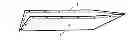
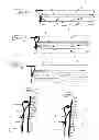
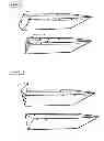
FIGS. 1 and 2 show a view of a containment device, the protective and/or treatment shell according to the invention, arranged on the mostly submerged portion of the hull of a ship.
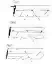
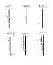
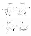
FIGS. 3, 4, 5, and 6 show diagrams of shells of various forms made of two portions, 1 and 2, building up the device, to adapt to different types of ships.
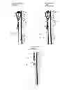
FIGS. 7, 8 and 9 show a type of final assembly of the two portions 1 and 2 building up the device;
FIGS. 10, 11, 12, 13 and 14 show temporary types of assemblies, with portions 1 and 2 separable or partly separable.
FIGS. 15, 16, 17, 18, 19, and 20 show various types of films.
FIGS. 21, 22, 23 show the possibility of adding a foamed plastic to the emerged portion 1.
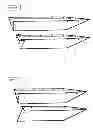
FIGS. 24 to 27 show variants of the closure of the rear portion.
FIGS. 28 to 31 show one possible setting up of the shell.
The entire device consists of
In the main embodiment, the device consists of at least two main portions 1 and 2 having features (physical or chemical) adapted to their respective different media: an emerged portion 1 surrounding the hull of the ship at or from the waterline, and secondly, a submerged portion 2 of a surface area always greater than the preceding, which includes the entirety of the submerged portion to protect 5 (in this example the hull of the ship), both portions 1 and 2 being assembled permanently, by stitching, gluing or welding fasteners, rivets 3 (FIGS. 7-9).
In this embodiment, the upper emerged portion 1 is made of a flexible material whose two main features are mechanical strength, (for example tensile strength above 10N/mm2 or 10 MPa), tear, lengthening and weathering resistance (particularly UV resistance). Flexibility is required as well as water resistance, but these features are less critical, the portion being only very partially in contact with water. Non limiting examples of materials: fabrics, films or PVC webs, nylon, polyurethane or polyurethane webbing, specially formulated PE or PP with additives or anti UV agents, reflective layer, complex combining the mentioned materials, . . .
In this embodiment, the constituent material of the outer side of at least the upper portion is thus selected for imparting to said upper portion a resistance to ultraviolet (UV) radiation that is higher than for the lower portion.
Higher resistance to ultraviolet (UV) radiation refers to the fact that the material comprising at least the outer portion of the upper portion retains a mechanical strength (tensile, break, shear) that is at least 3 times that of the lower portion, when they (emerged upper portion and lower portion) are directly exposed in an identical manner (same intensity, same duration, same wavelength) equaling a mean exposition in southern France for three years.
Other method of UV resistance characterization.
After being exposed for 3 years to the above described conditions, the material comprising at least the outer surface of the upper portion must retain at least 70% of its tensile strength, its tear resistance or its shear strength. Example: this material comprising at least the outer surface of the upper portion and having before exposition a tensile strength of 10N/mm2 (10 MPa) must retain a tensile strength of at least 7N/mm2 (7 MPa) after 3 years of exposition to the above described conditions.
On the other hand, after being exposed for 3 years to the same above described conditions, the material comprising at least the outer surface of the lower portion must retain less than 70% of its tensile strength, its tear resistance or its shear strength.
In this embodiment, the submerged portion 2 is made of a material whose main features are flexibility, resistance to water (hydrophobic), light weight (weight of preferably less than 500 g/m2) and a specific gravity of less than 1. Another advantageous feature is to provide a very low adhesion to marine organisms. This feature could optionally be improved in the case of a durable device because these organisms must be dislodged as easily as possible for ease of cleaning. Example: PE, reinforced or not, can be specifically formulated or surface-treated to improve the desired features.
In this embodiment, the submerged portion 2 may be partially or totally reinforced with woven or non-woven fibers.
In this main embodiment, the complete device is provided with means for attachment 6 (loop, hole, grommet) and fastening 8 (straps, ropes, sandow cords, hooks . . . ) mainly placed on the emerged portion 1 which allow for its placement and holding in place.
In another main embodiment, the emerged portion 1 and the submerged portion 2 are assembled together by a fastening system 4 which is reversible (FIGS. 10 to 14), i.e. fastening by means 4 (grommets, Velcro fasteners, clips, single or double sided adhesives, snaps, zippers) allowing for the simple and fast separation of these two portions. Portions 1 and 2 may therefore be dissociated for an optional replacement, of the lower portion 2 in most cases or of the upper portion 1 (for example in case of deterioration). For example, as an advantageous detail, the lower portion 2 can be manufactured in a less complex or thinner material which will be less expensive as a consequence and allow for more frequent replacements. The attachment means 6 are mainly placed on the upper portion 1 of the shell.
The two main embodiments detailed above allow for variants that can be applied to both embodiments. We therefore define variants for the emerged portion 1 and for the submerged portion 2. These variants may be advantageously blended in one or the other of the two main embodiments of the complete device we call a shell.
Below are detailed variants of the emerged portion 1 for the two main embodiments
Below are given several examples of embodiments of the emerged portion 1 of the device according to the invention:
-
- The emerged portion 1 is composed of a plastic film of PVC (polyvinyl chloride) optionally reinforced with a web.
- The emerged portion 1 is composed of a plastic film that may be selected from the following materials, optionally reinforced (for example with a web): polyurethane, hypalon, neoprene, polyester, polyethylene tetraphthalate, nylon, EPDM, Teflon, and more generally all plastics having an ultraviolet resistance of more than 3 years.
- The emerged portion 1 may according to another manufacturing embodiment be made of a layer of flexible plastic film and a fabric or braided fibers 9, a net or any backing material 9 on at least the surface (exposed to ultraviolet light) opposite to the hull of the ship (FIG. 15).
- The emerged portion 1 may in another embodiment consists of a complexed plastic film (at least 2 layers) (FIG. 16). Example: complex or multilayer, e.g. PVC/PE, PVC on the outer side for UV resistance and PE on the inside optionally allowing for the welding to the other PE building up the submerged portion 2.
- The emerged portion 1 may be made of a specifically formulated PE film (but more complex and expensive) for among other things a superior UV resistance. Special additives can be added to the PE base, e.g. carbon black pigments, UV (ultraviolet) absorbers, flame extinguishing agents (quenchers) or polyfunctional stabilizers, UV (ultraviolet) reflecting materials (e.g. aluminum).
- The emerged portion 1 may also be made of a plastic sheet of low specific gravity (e.g. less than 0.8) providing adequate lift so that this portion 1 floats, for example a foamed material 7 (such as EPDM or PVC) or any foam, in order to facilitate the setting-up and positioning of the device.
The emerged portion 1 may consists of at least one outer film (exposed to ultraviolet light) and mostly opposite to the portion to protect, to be selected from any of the following non-limiting materials: PVC, polyurethane, hypalon, nylon, with an ultraviolet resistance that is superior to the materials making up portion 2, trapping a foamed material 7, see FIGS. 21 and 22 (preferably with closed cells), or covering it at least on its surface (exposed to ultraviolet light) and mainly opposite to the hull, see FIG. 23 (e.g. polyethylene, EPDM or PVC, or any foam).
Below are detailed variants of the submerged portion 2 for the two main embodiments
Below are given several examples of embodiments of the submerged portion 2 of the device according to the invention:
-
- The submerged portion 2 consists of a polyethylene film or shell
- The submerged film 2 consists of a film or shell of a plastic selected from polyolefins
- The submerged portion 2 is impervious to water.
- The submerged portion 2 is permeable, drilled with a plurality of holes of less than 4 mm2, but sufficient to let through or diffuse a fluid.
- The submerged portion 2 may be comprised of at least 2 films of materials having the same composition, i.e. several layers or films forming an indivisible single layer or film, which when assembled in a particular way provide different features due to the multilayer complex. For example, a PE/PE complex where layers are cross-orientated to increase mechanical strength.
- The submerged portion 2 may itself be made of several films of materials 2 and 2b is (FIGS. 13, 17, and 22), of differing compositions or thicknesses or physical features (non limiting example: specific gravity). That is to say, of several indivisible complexed layers (Example: PE/PP complex) or films of the same material with specific distinct properties (e.g. HDPE and LDPE), these films being non-cleavable complexes.
- For the submerged portion 2, in the case of a complex of several layers, the film or at least the inner layer which will be in contact with the hull may advantageously be made of a material 9 (FIG. 18) facilitating the sliding against the hull (non-limiting example: nonwoven polypropylene fiber, FIG. 18) during the setting-up—and will protect the intermediate layer(s) from tear.
- The submerged portion 2 may be made of an anti-adhesive material resistant to the adhesion of aquatic organisms (non-limiting example: silicone film).
- The submerged portion 2 may be rendered non-adhesive for resisting to the adhesion of aquatic organisms at least on the surface opposite to the portion 5 to protect, by introducing anti-adhesive agents or glidants in the base material such as a polyolefin, during the manufacturing process (non-limiting examples: paraffin, stearate, oleamide . . . )
- The submerged portion 2 may be made of a complexed material with at least the outer layer or surface opposite to the surface to protect made of an anti-adhesive material (in the case of a multilayer outer film)
- The submerged portion 2 may be made of a material of which at least the surface opposite the surface to protect will be made anti-adhesive by surface treatment after the film manufacturing. The glidant (non-limiting example: silicone, paraffin) is applied on the surface of the shell by coating, impregnation, gluing or adhesive bonding, or corona process.
- The submerged portion 2 may itself consist of several films of materials the properties of which are identical or not, cleavable or stripable, peelable, films adhering together with the appearance of a single film comprised of several easily separable layers. These complexes are constituted of easily separable films, providing a way to remove and recycle a layer as soon as it is deteriorated or covered with aquatic organisms. These layers can be of various thicknesses e.g. a few microns (non-limiting example: 10 to 60 μm)
- The submerged portion 2 may be made of a plastic material on which an active repelling or biocidal molecule is grafted to the carbon chain during its manufacturing, for example a chlorpyriphos-ethyl/bifenthrine.
- The submerged portion 2 may be made of a plastic material on which is included a repellent or biocidal product on at least the surface opposite to the surface to protect.
- The submerged portion 2 may be a complex wherein at least the outer film opposite to the surface to protect contains a repellent or biocidal product.
In another variant, the submerged portion 2 or 2b is may be completely disposable and recyclable (FIGS. 14 to 21) (or only the last layer in FIGS. 13 and 22) in case of e.g. aging or deterioration. This film may be more fragile, thinner (non-limiting example: 40 μm) and therefore lighter, in order to reduce maintenance time before sailing, by suppressing the cleanup phase of the submerged portion 2.
In another embodiment, the submerged portion 2 has a thickness of less than 500 μm.
In another embodiment, the submerged portion 2 is partially reinforced by a strip of non-woven fibers or another additional film or layer 9 (FIG. 20) in its upper portion on one surface of the submerged portion 2.
In another embodiment, the submerged portion 2 is reinforced in areas suffering from friction or additional strain (propeller, keel . . . ) by a layer of non-woven fibers or another film to increase their resistance.
In another embodiment, the submerged portion 2 may have imprints or embossings or is padded (e.g. geogrids or textiles) on its inner portion to allow for movement of fluids in the spaces created after contact with the hull (FIG. 19).
According to Other Aspects of the Invention for the Entire Device
In one embodiment, the attachment means 6 are mainly placed on the upper portion 1 of the shell.
In another embodiment, the attachment means 6 are exclusively placed on the upper portion 1 of the shell.
In another embodiment, the shell is open on the rear and the lower portion 2 is in line with the upper portion 1 (FIGS. 3 and 4).
In one embodiment, the shell is open on the rear and the lower portion 2 is set back with respect to the upper portion 1 (FIG. 5).
In one embodiment, the shell is open on the rear and the lower portion 2 is set forward with respect to the upper portion 1 (FIG. 6).
In another embodiment, the shell may be closed on the rear by upward folding (FIG. 24).
In one embodiment, the shell is closed by crossing both sides of the shell and/or covering one side with the other on the rear (FIG. 25).
In another embodiment, the rear closing of the shell may be hood-shaped (FIG. 26).
In another embodiment, the shell may be closed on the rear by closing a flap downwards (FIG. 27).
In another embodiment, the submerged portion 2 is impervious and provided with at least one check valve to let the trapped water leave out and to preclude or minimize flow in the opposite direction.
In another embodiment, the submerged portion 2 is impervious and provided with at least one valve or adjustable opening.
In another embodiment, portions 1 and 2 may have backing hems 11 through which ropes or straps can be passed to adjust, place or tighten the entire device against the hull (FIG. 3).
The device is set up and maintained by ropes, sandow cords, carabiners 8.
FIGS. 28 to 31 show an example of setting-up of the entire device.
Claims
1. Device for protecting an object floating or resting on an aquatic floor having at least one submerged surface (5), comprising a flexible shell suitable for wrapping around said submerged surface, wherein said flexible shell comprises a lower portion (2) which when the shell is set up so as to wrap around the submerged surface, is mainly submerged and wraps around the majority of the submerged surface (5) to protect, and an upper portion (1) which, when the shell is set up so as to wrap around the submerged surface, is partly emerged, the upper portion (1) of the shell having a surface area inferior to that of the lower portion (2), in that at least the respective external sides of the upper portion 1 and lower portion 2 of the shell are made of different materials.
2. Device according to claim 1, wherein the upper portion (1) and the lower portion (2) are permanently assembled and affixed to each other.
3. Device according to claim 1, wherein the upper portion (1) and the lower portion (2) are temporarily assembled.
4. Device according to, claim 1, wherein the upper (1) and lower (2) portions of the shell are made of materials of different densities.
5. Device according to claim 1, wherein at least the outer side of the upper portion (1) has features of ultraviolet (UV) radiation resistance superior to those of the lower portion (2).
6. Device according to claim 1, wherein:
the upper portion (1) of the shell is made at least on its outer side of one of the following materials: PVC, polyurethane, hypalon, nylon,
the lower portion (2) of the envelope is mainly made of a polyolethylene film.
7. Device according to claim 1, wherein the upper portion (1) of the shell consists of a plurality of layers of different materials, whether complexed or not to each other.
8. Device according to claim 7, wherein the upper portion (1) of the shell comprises at least two layers, including a substrate and a outer coating film onto the substrate and having higher UV resistance than the substrate.
9. Device according to claim 1, wherein the upper portion (1) of the shell comprises an inner layer placed on the side of the object to protect or included in a hem and is made of a material of specific gravity lower than 0.9.
10. Device according to claim 1, wherein the lower portion of the shell has a specific gravity of less than 1.
11. Device according to claim 1, wherein the lower portion of the shell has a weight of less than 0.5 g/m2.
12. Device according to claim 1, wherein the lower portion of the shell consists of a plurality of layers of different materials, whether complexed or not to each other.
13. Device according to claim 11, wherein the lower portion of the shell comprises at least one outer layer at least partly separable.
14. Device according to claim 1, wherein the lower portion of the shell is made at least on its outer side opposite to the object to protect, in a treated material which is formulated to provide anti-adhering properties.
15. Device according to claim 1, wherein the upper portion of the shell is provided with means for fastening it to the object to protect.
Images & Drawings included:
Sources:
- United States Patent and Trademark Office - verify current appl. status at the USPTO↗
Recent applications in this class:
- » 20240124106 2024-04-18
Boat Hull Protection System and Methods of Using Same - » 20230391428 2023-12-07
AN ANTI-FOULING PROTECTIVE COVER - » 20230242224 2023-08-03
FORMABLE AQUATIC COVERINGS FOR PREVENTING BIOFOULING - » 20210291944 2021-09-23
A WATER VESSEL HULL PROTECTOR AND METHOD OF CONSTRUCTION - » 20210221482 2021-07-22
Inflation-based antifouling - » 20210009242 2021-01-14
Formable aquatic coverings for preventing biofouling - » 20200339234 2020-10-29
Submersible sensor unit - » 20200298943 2020-09-24
SYSTEM AND METHOD FOR PREVENTING FOULING AND/OR CORROSION ON VESSELS AND MARINE OBJECTS - » 20200055578 2020-02-20
VENT FOR SHRINK WRAP WATERCRAFT STORAGE - » 20190367140 2019-12-05
Active Energy Ray Curable Resin Composition for Use Around Water, Anti-Fouling Laminate for Use Around Water, Method for Manufacturing Same, and Product for Use Around Water