Heat exchange element, a heat exchanger comprising the elements, and an equipment for the manufacture of the elements
US20130146226A1
2013-06-13
13/583,025
2010-03-08
✅ Patent granted
US 9,372,033 B2
2016-06-21
WO; PCT/FI2010/050172; 20100308
WO; WO2011/110726; 20110915
M. Alexandra Elve | Paul Alvare
Young & Thompson
2031-08-24
Abstract:
A heat exchange element of flexible plastic film, a heat exchanger including such elements, and apparatus for manufacturing the elements are described. The element includes a pair of opposite film sheets bonded by welds to form an expandable bag with inside and outside heat exchange surfaces, an inlet opening for supplying a pressurized heat exchange fluid to the bag, an outlet opening for discharging the fluid from the bag after heat exchange, and an array of welds defining routes for fluid flow inside the bag. There are spot welds in a first zone of the element, parallel extended welds in a second zone of the element, defining fluid flow channels through the second zone, and oblique welds in a third zone of the element, defining channels for fluid flow towards the outlet opening. The heat exchanger includes a pack of adjacent elements for heat exchange between a pressurized first fluid.
Inventors:
- Leif Ramm-Schmidt 2 🇫🇮 Espoo, Finland
- Arun Ganesaraman 1 🇮🇳 Chennai, India
- Arun Ganesaraman 1 🇮🇳 Tamilnadu, India
Assignee:
- ARVIND ACCEL LIMITED 1 🇮🇳 Ahmedabad, India
Applicant:
Interested in similar patents?
Get notified when new applications in this technology area are published.
Classification:
F28D9/0087 » CPC main
Heat-exchange apparatus having stationary plate-like or laminated conduit assemblies for both heat-exchange media, the media being in contact with different sides of a conduit wall with flexible plates
F28D9/00 IPC
Heat-exchange apparatus having stationary plate-like or laminated conduit assemblies for both heat-exchange media, the media being in contact with different sides of a conduit wall
B29C66/1122 » CPC further
General aspects of processes or apparatus for joining preformed parts; General aspects dealing with the joint area or with the area to be joined; Particular design of joint configurations particular design of the joint cross-sections; Joint cross-sections comprising a single joint-segment, i.e. one of the parts to be joined comprising a single joint-segment in the joint cross-section; Single lapped joints Single lap to lap joints, i.e. overlap joints
B01D1/221 » CPC further
Evaporating by bringing a thin layer of the liquid into contact with a heated surface Composite plate evaporators
B29C66/21 » CPC further
General aspects of processes or apparatus for joining preformed parts; General aspects dealing with the joint area or with the area to be joined; Particular design of joint configurations particular design of the joint lines, e.g. of the weld lines said joint lines being formed by a single dot or dash or by several dots or dashes, i.e. spot joining or spot welding
B29C66/221 » CPC further
General aspects of processes or apparatus for joining preformed parts; General aspects dealing with the joint area or with the area to be joined; Particular design of joint configurations particular design of the joint lines, e.g. of the weld lines said joint lines being in the form of recurring patterns being in the form of a sinusoidal wave
B29C66/232 » CPC further
General aspects of processes or apparatus for joining preformed parts; General aspects dealing with the joint area or with the area to be joined; Particular design of joint configurations particular design of the joint lines, e.g. of the weld lines said joint lines being multiple and parallel or being in the form of tessellations said joint lines being multiple and parallel, i.e. the joint being formed by several parallel joint lines
B29C66/41 » CPC further
General aspects of processes or apparatus for joining preformed parts; General aspects of joining substantially flat articles, e.g. plates, sheets or web-like materials; Making flat seams in tubular or hollow articles; Joining single elements to substantially flat surfaces Joining substantially flat articles ; Making flat seams in tubular or hollow articles
B29C66/81433 » CPC further
General aspects of processes or apparatus for joining preformed parts; General aspects of machine operations or constructions and parts thereof; General aspects of the pressing elements, i.e. the elements applying pressure on the parts to be joined in the area to be joined, e.g. the welding jaws or clamps characterised by the design of the pressing elements, e.g. of the welding jaws or clamps characterised by the surface geometry of the part of the pressing elements, e.g. welding jaws or clamps, coming into contact with the parts to be joined being toothed, i.e. comprising several teeth or pins , or being patterned
B29C66/81435 » CPC further
General aspects of processes or apparatus for joining preformed parts; General aspects of machine operations or constructions and parts thereof; General aspects of the pressing elements, i.e. the elements applying pressure on the parts to be joined in the area to be joined, e.g. the welding jaws or clamps characterised by the design of the pressing elements, e.g. of the welding jaws or clamps characterised by the surface geometry of the part of the pressing elements, e.g. welding jaws or clamps, coming into contact with the parts to be joined being toothed, i.e. comprising several teeth or pins , or being patterned comprising several parallel ridges, e.g. for crimping
B29C66/81465 » CPC further
General aspects of processes or apparatus for joining preformed parts; General aspects of machine operations or constructions and parts thereof; General aspects of the pressing elements, i.e. the elements applying pressure on the parts to be joined in the area to be joined, e.g. the welding jaws or clamps characterised by the design of the pressing elements, e.g. of the welding jaws or clamps characterised by the constructional aspects of the pressing elements, e.g. of the welding jaws or clamps comprising a plurality of single pressing elements, e.g. a plurality of sonotrodes, or comprising a plurality of single counter-pressing elements, e.g. a plurality of anvils, said plurality of said single elements being suitable for making a single joint one placed behind the other in a single row in the feed direction
B29C65/18 » CPC further
Joining of preformed parts ; Apparatus therefor by heating, with or without pressure using heated tools
F28F21/06 IPC
Constructions of heat-exchange apparatus characterised by the selection of particular materials of plastics material
B29C66/83415 » CPC further
General aspects of processes or apparatus for joining preformed parts; General aspects of machine operations or constructions and parts thereof characterised by the movement of the joining or pressing tools moving with the parts to be joined; Roller, cylinder or drum types; Band or belt types; Ball types; Roller, cylinder or drum types the contact angle between said rollers, cylinders or drums and said parts to be joined being a non-zero angle
F28F3/12 » CPC further
Plate-like or laminated elements; Assemblies of plate-like or laminated elements Elements constructed in the shape of a hollow panel, e.g. with channels
B29C66/8242 » CPC further
General aspects of processes or apparatus for joining preformed parts; General aspects of machine operations or constructions and parts thereof; Pressure application arrangements, e.g. transmission or actuating mechanisms for joining tools or clamps; Actuating mechanisms Pneumatic or hydraulic drives
B29L2022/02 » CPC further
Hollow articles Inflatable articles
B29L2031/18 » CPC further
Other particular articles Heat-exchangers or parts thereof
B29L2031/7128 » CPC further
Other particular articles; Containers; Packaging elements or accessories, Packages Bags, sacks, sachets
F28F2255/02 » CPC further
Heat exchanger elements made of materials having special features or resulting from particular manufacturing processes Flexible elements
F28F7/00 IPC
Elements not covered by group , or
F28B9/10 IPC
Auxiliary systems, arrangements, or devices for extracting, cooling, and removing non-condensable gases
F28D5/02 IPC
Heat-exchange apparatus having stationary conduit assemblies for one heat-exchange medium only, the media being in contact with different sides of the conduit wall, using the cooling effect of natural or forced evaporation in which the evaporating medium flows in a continuous film or trickles freely over the conduits
F28F13/00 IPC
Arrangements for modifying heat-transfer, e.g. increasing, decreasing
F28F3/14 IPC
Plate-like or laminated elements; Assemblies of plate-like or laminated elements; Elements constructed in the shape of a hollow panel, e.g. with channels by separating portions of a pair of joined sheets to form channels, e.g. by inflation
B29C65/06 IPC
Joining of preformed parts ; Apparatus therefor by heating, with or without pressure using friction, e.g. spin welding
B29C65/00 IPC
Joining of preformed parts ; Apparatus therefor
B32B37/00 IPC
Methods or apparatus for making layered products; Treatment of the layers or of the layered products
B32B37/00 IPC
Methods or apparatus for laminating, e.g. by curing or by ultrasonic bonding
B32B41/00 IPC
Arrangements for controlling or monitoring lamination processes; Safety arrangements
G05G15/00 IPC
Mechanical devices for initiating a movement automatically due to a specific cause
B01D1/22 IPC
Evaporating by bringing a thin layer of the liquid into contact with a heated surface
B29D7/01 » CPC further
Films or sheets
B29C66/83413 » CPC further
General aspects of processes or apparatus for joining preformed parts; General aspects of machine operations or constructions and parts thereof characterised by the movement of the joining or pressing tools moving with the parts to be joined; Roller, cylinder or drum types; Band or belt types; Ball types; Roller, cylinder or drum types cooperating rollers, cylinders or drums
F28F3/00 IPC
Plate-like or laminated elements; Assemblies of plate-like or laminated elements
F28F21/065 » CPC further
Constructions of heat-exchange apparatus characterised by the selection of particular materials of plastics material the heat-exchange apparatus employing plate-like or laminated conduits
B65C9/40 IPC
Details of labelling machines or apparatus Controls; Safety devices
Description
The invention relates to a heat exchange element of flexible plastic film material, a heat exchanger comprising a plurality of such heat exchange elements, as well as an equipment for the manufacture of the heat exchange elements.
More particularly, the invention comprises a heat exchange element of flexible plastic film material bonded to form an expandable bag with inside and outside heat exchange surfaces, the element comprising an inlet opening for supplying a pressurized heat exchange fluid flow, an outlet opening for discharging the fluid flow after heat exchange, and an array of welds bonding the opposite plastic films to define routes for vertical fluid flow through subsequent heat exchange zones inside the bag. The heat exchanger according to the invention has a pack of such heat exchange elements, with the pressurized heat exchange fluid arranged to be fed inside each of the elements, and another heat exchange fluid flow arranged to be fed to each of the gaps left between the elements. An example of such a heat exchanger is a distiller, which evaporates liquid flowing between the elements and, after pressurizing of the vapor, condenses it back to liquid inside the elements.
In the prior art, WO 90/01977 describes a distillation apparatus consisting of a pack of upright heat exchange elements comprised of pairs of plastic film membranes, which have spot welds between the membranes to define passages for heat exchange fluid flow. Water to be distilled is led from a distributor basin above the elements to the outer surfaces of the adjacent elements, evaporated between the elements, and the vapor is then collected and sucked to a blower, which blows it inside the elements at a higher pressure. The heat exchange between the inside and the outside of the adjacent elements condenses the vapor back to liquid. Each element has a vapor inlet opening extending along a vertical side edge in the upper part of the element, and a liquid outlet opening in the lowermost corner of a sloping bottom of the element. The apparatus is aimed at the production of fresh water from saline sea water.
WO 92/10264 and WO 92/10265 show a modification of the distillation apparatus according to WO 90/01977, in which both the liquid to be evaporated between the bag-like heat exchange elements and the pressurized vapor to be condensed in the inside of the elements are supplied through distributor strips at the top end of the adjacent elements. Another change is that the inside of each element has been divided to parallel vertical, zigzagging fluid flow channels, by means of correspondingly zigzagging weld lines between the pair of film membranes defining the element.
WO 98/33029 shows as another modification a bag-like heat exchange element with sinuous welds defining correspondingly sinuous flow channels for fluid flow inside the element. The welds extend from the top end of each element to a tapered bottom, collecting the fluid condensed within the element to a centrally located discharge opening. The apparatus is meant for the evaporation of industrial waste water with a content of suspended solid matter, separating as a residue, which passes the relatively narrow condensate discharge openings and thus provides for self-cleaning taking place in the evaporator.
DE 25 11 144 describes an evaporator, in which vertical heat exchange elements of plastic material comprise a spot welded vapour distributor zone and a horizontally and vertically channelled heat exchange zone located beside each other. Hot vapour is supplied from a vertical side of the evaporator to the inside of each element, passed through the spot welded vapour distributor zone, and led to the horizontal and vertical channels of the heat exchange zone, to be condensed and discharged as condensed liquid through an outlet opening at the bottom of the element. A solution to be evaporated is supplied from the top of the evaporator to the outer surfaces of the heat exchange elements, to flow downward and evaporate between the expanded horizontal and vertical channels of the heat exchange zone.
In comparison with the spot welds the sinuous or zigzagging welds have the benefit of forming pathways for fluid flow between the elements which are not easily clogged, especially if the elements are arranged so as to have every second element turned to a mirror-image position in regard of the neighbouring elements. In such an arrangement the expanded sinuous flow channels of the neighbouring elements regularly cross each other, and form pathways outside the elements, which crisscross around those sinuous expansions. Spot welds, especially in a face-to face position in neighbouring elements tend to thin down the pathways between the expanded elements and suppress the fluid flow. As fibrous suspensions are evaporated the flow pathways are easily clogged. The sinuous weld configuration can also withstand higher pressure differences than spot welds and provides superior liquid distribution.
A drawback of the sinuous weld configurations of the prior art heat exchangers is that the fluid flow distribution structures at the top of the elements are bulky, due to the double feed channel arrangements supplying the fluid flows to the inside and to the outside of each element, respectively. The thickness of the double feed channel structure then sets a minimum for the expansion of the elements, so as to bring the surfaces of the neighbouring elements into contact with each other. Therefore restricting the expansion in order to increase the number of heat exchange surfaces and thereby the heat exchanging capacity in a given volume is not possible.
The goal of the invention is to provide an improved heat exchange element, in which the above drawbacks have been avoided. In other words, the invention aims at an easy flow of fluids between adjacent heat exchange elements while the elements have a high resistance to wear under high pressure conditions and an improved capacity due to restricted expansion and increased heat exchange surface area. The solution provided by the invention is a heat exchange element, in which there is an array of spot welds in an uppermost first zone of the element adjacent to the inlet opening, an array of parallel extended welds in a second zone of the element below said first zone, said extended welds defining fluid flow channels through the second zone, and an array of oblique welds in a lowermost third zone of the element below said second zone, said oblique welds defining channels for fluid flow towards the outlet opening.
Spot welds in the uppermost first zone of the element permit a free lateral spread of fluid, usually pressurized vapor, which is thereby evenly distributed to the flow channels in the second zone below. The vapor inlet opening can thus be located on a vertical side of the element, separated from the inlet channels which feed a fluid to the outside of the elements. The thickness of the feed channel structure at the top end of the elements is only determined by the latter, resulting in a lesser expansion of individual elements required to bring the element surfaces into contact with each other. Furthermore, by increasing the number of spot welds the expansion in the first zone can be reduced and made to be less than in the second zone, which would improve the fluid flow between the uppermost parts of the adjacent elements.
According to a preferred embodiment of the invention the element comprises an array of parallel sinuous welds defining parallel sinuous fluid flow channels extending vertically through the second zone of the element. However, the invention even covers linear welds in the second zone, useful particularly in a gas-to-gas heat exchanger.
The first and second zones of the heat exchange element may be generally rectangular, whereas the third zone is tapering towards the outlet opening. In the heat exchanger the heat exchange elements are usually standing in an upright position, and the outlet opening is lying at the lowermost end of the element, with the fluid flow channels in the third zone converging towards the outlet opening.
The heat exchanger according to the invention comprises a pack of adjacent heat exchange elements of flexible plastic film material, each element having the form of an expandable bag with inside and outside heat exchange surfaces to enable heat exchange between a pressurized first fluid flowing inside the elements and a second fluid flowing between the adjacent elements, and each element comprising an inlet opening for supplying said first fluid, an outlet opening for discharging the first fluid after heat exchange, and an array of welds bonding the opposite plastic films to define routes for vertical fluid flow through subsequent heat exchange zones inside the bag. The heat exchanger of the invention is characterized in that in each heat exchange element there is an array of spot welds in an uppermost first zone of the element adjacent to the inlet opening, an array of parallel extended welds in a second zone of the element below said first zone, said extended welds defining fluid flow channels through the second zone, and an array of oblique welds in a lowermost third zone of the element below said second zone, said oblique welds defining channels for fluid flow towards the outlet opening.
The equipment for the manufacture of heat exchange elements according to the invention is characterized in that it comprises a path of travel for a web of double plastic sheet material for provision of a plurality of bag-like elements, a succession of three heatable weld rolls along said path, said three rolls having protrusions for forming welds of three specific different configurations, respectively, and being provided with hydraulic or pneumatic means to selectively bringing the rolls into contact with the moving web and out of contact with it, and a backing roll on the opposite side of the web supporting the weld rolls brought into contact with the web.
The invention is now described in more detail by way of examples with reference to the attached drawings, in which
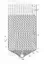
FIG. 1 is a front view of a heat exchange element according to the invention,
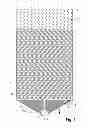
FIG. 2 is a partial front view of two adjacent heat exchange elements according to FIG. 1, partly in section,
FIG. 3 is a front view of the upper left corner of an element according to claim 1, as section IV-IV from FIG. 4, including inlet channels for the heat exchange fluids,
FIG. 4 is a cross-section of part of a heat exchanger comprising a pack of heat exchange elements according to FIG. 1, as section III-III from FIG. 3, and
FIG. 5 is a schematic illustration of an equipment for the manufacture of heat exchange elements according to the invention,
FIG. 1 shows a heat exchange element 1 comprising a pair of sheets of flexible plastic film material bonded to form an expandable bag with inside and outside heat exchange surfaces. The element 1 belongs to a heat exchanger comprising a pack of adjacent elements bound to each other by clamping means. One of the heat exchange fluids is pressurized gas or vapor flowing inside the elements 1 and expanding the elements so as to press the heat exchange film surfaces of adjacent elements into contact with each other. The other heat exchange fluid flows between the elements 1, along the outer heat exchange surfaces thereof.
The heat exchange element 1 according to FIG. 1 comprises an inlet opening 2 for supplying a pressurized heat exchange fluid flow, an outlet opening 3 for discharging the fluid flow after heat exchange, and an array of welds 4, 5, 6 bonding the opposite plastic film sheets to define routes for fluid flow inside the bag. The element is divided into three zones 7, 8, 9 in the direction of travel of the fluid inside the elements, generally downward in an element positioned vertically, the zones having welds of different configuration bonding the film sheets to each other and defining routes for fluid flow inside the element. In the first zone 7 adjacent to the inlet opening 2 there is an array of spot welds 4, permitting spread of the fluid in a lateral direction. The inlet opening 2 is located on a vertical side 10 of the element beside the first zone 7. In the second zone 8 following the first zone 7 there is an array of parallel sinuous welds 5 defining correspondingly sinuous fluid flow channels 11 extending vertically through the second zone. In the third zone 9 following the second zone 8 there is an array of oblique welds 6 defining channels 12 for fluid flow converging towards the lowermost outlet opening 3. In the area of the first and second zones 7, 8 the form of the element 1 is rectangular, having a horizontal top end 13 end and vertical side edges 10, whereas in the third zone 9 the bottom 14 of the element tapers symmetrically towards the axially lowermost outlet opening 3.
FIG. 2 shows parts of two adjacent heat exchange elements 1, 1′ as positioned in a pack of elements constituting a heat exchanger 15 according to the invention. It may be seen that the sinuous flow channels 11 of the neighbouring elements 1, 1′ are in a mutually displaced or mirror-image position, so that the expanded channels regularly cross each other and leave pathways 16 outside the elements, which crisscross around the channels. FIG. 4 showing a pack of elements in cross-section is a further illustration of the mutual position of the expanded channels 11 in neighbouring elements 1, 1′.
As seen in FIGS. 3 and 4 the inlet opening 2 of each heat exchange element 1 is provided with a vertical bar 17 comprising a set of pressurized fluid feed channels 18 leading to the first zone 7 having spot welds 4. Along the top ends 13 of the elements there is a horizontal fluid distributor structure comprising adjacent bars 19, each with a set of feed channels 20, which distribute heat exchange fluid onto the heat exchange surfaces between the elements. The ends of the vertical and horizontal bars 17, 19 are stacked in alternation and bound together by means of a bolt 21 penetrating each of the elements in the pack.
A heat exchanger with a pack of heat exchange elements according to FIG. 1 may be used as a distiller, in which liquid is evaporated between the adjacent elements, the vapour generated from the liquid is raised to a higher pressure and temperature by means of a blower (not shown), and the vapor is then condensed back to liquid inside the elements and discharged from the elements as distillate. Another possible uses are heat exchange from a gas of a higher temperature to a gas of a lower temperature, the gas with the higher pressure flowing within the elements and the gas with the lower pressure flowing between the elements, and evaporation of fibrous or other suspensions to reduce their volume and separate their solid contents as the fluid flows in the gaps and pathways between the compressed elements, the solids being removed therefrom by way of a self-cleaning effect.
An equipment for the manufacture of the heat exchange elements 1 is depicted schematically in FIG. 5. The equipment has a path of travel for a web 22 of double plastic sheet material for provision of a plurality of bag-like elements, a succession of three heatable weld rolls 23, 24, 25 along said path, the three rolls having protrusions for forming welds of three different configurations, respectively, and being provided with hydraulic or pneumatic means (not shown) to selectively bringing the rolls into contact with the moving web and out of contact with it, and a backing roll 26 on the opposite side of the web supporting the weld rolls brought into contact with the web. To produce an element as seen in FIG. 1 the three rolls have protrusions for forming welds of spot, sinuous and converging configuration, respectively. The welded plastic sheet web is taken up to roll 27, and cut to individual elements 1 at a later stage.
Claims
1. Heat exchange element (1) of flexible plastic film material bonded to form an expandable bag with inside and outside heat exchange surfaces, said element comprising an inlet opening (2) for supplying a pressurized heat exchange fluid flow, an outlet opening (3) for discharging the fluid flow after heat exchange, and an array of welds (4-6) bonding the opposite plastic films to define routes for vertical fluid flow through subsequent heat exchange zones inside the bag, characterized in that there is an array of spot welds (4) in an uppermost first zone (7) of the element adjacent to the inlet opening (2), an array of parallel extended welds (5) in a second zone (8) of the element below said first zone, said extended welds defining fluid flow channels (11) through the second zone, and an array of oblique welds (6) in a lowermost third zone (9) of the element below said second zone, said oblique welds defining channels (12) for fluid flow towards the outlet opening (3).
2. Heat exchange element according to claim 1, characterized in that the second zone (8) comprises an array of parallel sinuous welds (5) defining parallel sinuous fluid flow channels (11).
3. Heat exchange element according to claim 1, characterized in that the first and second zones (7, 8) of the heat exchange element (1) are generally rectangular, whereas the third zone (9) is tapering towards the outlet opening (3).
4. Heat exchange element according to claim 3, characterized in that the outlet opening (3) lies axially at the lowermost end of the element (1) set in an upright position, the fluid flow channels (12) in the third zone (9) converging towards the outlet opening.
5. Heat exchange element according to claim 4, characterized in that the upright element has a horizontal top end (13), two vertical sides (10) and a tapering bottom end (14) with the outlet opening (3), the inlet opening (2) lying on a vertical side beside said first zone (7).
6. Heat exchange element according to claim 1, characterized in that the element (1) is worked for condensing pressurized vapor or humidity to liquid, which is discharged from the lowermost outlet opening (3) of the element.
7. Heat exchanger (15) comprising a pack of adjacent heat exchange elements (1) of flexible plastic film material, each element having the form of an expandable bag with inside and outside heat exchange surfaces to enable heat exchange between a pressurized first fluid flowing inside the elements and a second fluid flowing between the adjacent elements (1, 1′), and each element comprising an inlet opening (2) for supplying said first fluid, an outlet opening (3) for discharging the first fluid after heat exchange, and an array of welds (4, 5, 6) bonding the opposite plastic films to define routes for vertical fluid flow through subsequent heat exchange zones inside the bag, characterized in that in each heat exchange element (1) there is an array of spot welds (4) in an uppermost first zone (7) of the element adjacent to the inlet opening (2), an array of parallel extended welds (5) in a second zone (8) of the element below said first zone, said extended welds defining fluid flow channels (11) through the second zone, and an array of oblique welds (6) in a lowermost third zone (9) of the element below said second zone, said oblique welds defining channels (12) for fluid flow towards the outlet opening (3).
8. Heat exchanger according to claim 7, characterized in that the first and second zones (7, 8) of each heat exchange element (1) are generally rectangular, whereas the third zone (9) is tapering towards the outlet opening (3).
9. Heat exchanger according to claim 8, characterized in that the heat exchange elements (1) are in an upright position and the outlet opening (3) is at the lowermost end of each element.
10. Heat exchanger according to claim 9, characterized in that each heat exchange element (1) has a horizontal top end (13), two vertical sides (10) and a tapering bottom end (14) with the outlet opening (3), the inlet opening (2) lying on a vertical side beside said first zone (7).
11. Heat exchanger according to claim 10, characterized in that there is a horizontal fluid distributor structure (19) adjacent to the top ends (13) of the heat exchange elements (1), said structure comprising feed channels (20) distributing fluid onto the heat exchange surfaces between the elements.
12. Heat exchanger according to claim 11, characterized in that the fluid distributor structure comprises horizontal bars (19) containing a set of fluid feed channels (20), the bars being arranged in alternation with the top ends (13) of the flexible heat exchange elements (1).
13. Heat exchanger according to claim 12, characterized in that the inlet opening (2) of each heat exchange element (1) is provided with a vertical bar (17) comprising a set of vapor feed channels (18), said horizontal and vertical bars (19, 17) having their adjacent ends stapled and bound to each other in alternation.
14. Heat exchanger according to claim 9, characterized in that it is worked for condensing pressurized vapor or humidity to liquid, which is discharged from the lowermost outlet openings (3) of the heat exchange elements (1).
15. Heat exchanger according to claim 14, characterized in that it is a distiller evaporating liquid between the adjacent heat exchange elements (1, 1′), pressurizing the vapour generated from said liquid, and condensing the vapor back to liquid inside the heat exchange elements.
16. Equipment for the manufacture of heat exchange elements (1) according to claim 1, characterized in that it comprises a path of travel for a web (22) of double plastic sheet material for provision of a plurality of bag-like elements, a succession of three heatable weld rolls (23-25) along said path, said three rolls having protrusions for forming welds of three different configurations, respectively, and being provided with hydraulic or pneumatic means to selectively bringing the rolls into contact with the moving web and out of contact with it, and a backing roll (26) on the opposite side of the web supporting the weld rolls brought into contact with the web.
17. Equipment according to claim 16, characterized in that the three rolls (23-25) have protrusions for forming welds (4-6) of spot, sinuous and converging configuration, respectively.
18. Heat exchange element according to claim 2, characterized in that the first and second zones (7, 8) of the heat exchange element (1) are generally rectangular, whereas the third zone (9) is tapering towards the outlet opening (3).
Images & Drawings included:


Sources:
- United States Patent and Trademark Office - verify current appl. status at the USPTO↗
Recent applications in this class:
- » 20190101334 2019-04-04
Plate and Frame Heat Exchangers with Variable Chamber Sizes - » 20150136360 2015-05-21
THERMAL INTERFACE PAD AND PRODUCTION METHOD THEREOF, AND HEAT DISSIPATING SYSTEM - » 20050061473 2005-03-24
Flexible heat exchangers