Pulse width modulation controller
US20130147414A1
2013-06-13
13/614,864
2012-09-13
✅ Patent granted
US 9,124,092 B2
2015-09-01
-
-
Bentsu Ro | Thai Dinh
Mintz Levin Cohn Ferris Glovsky and Popeo, P.C. | Peter F. Corless
2033-05-13
Abstract:
Disclosed herein is a Pulse Width Modulation (PWM) controller. The PWM controller includes a plurality of Field Effect Transistors (FETs) and an FET driver. A comparator compares a current flowing through the FETs with an overcurrent reference value, and microcomputer controls a motor and a circuit protection function, and turns off the FET driver when the current flowing through the FETs is greater than the overcurrent reference value as a result of comparison by the comparator.
Inventors:
- Ho Deuk Song 4 🇰🇷 Seoul, South Korea
- Sang Hyun Jang 4 🇰🇷 Yongin, South Korea
- Jong Hoon Chae 1 🇰🇷 Hwaseong, South Korea
- Sang-Hyun Jang 5 🇰🇷 Gyeonggi-do, South Korea
- Jong Hoon Chae 1 🇰🇷 Gyeonggi-do, South Korea
Assignee:
- Kia Motors Corporation 8,327 🇰🇷 Seoul, South Korea
- Hyundai Motor Company 20,646 🇰🇷 Seoul, South Korea
Applicant:
Interested in similar patents?
Get notified when new applications in this technology area are published.
Classification:
H02P7/29 IPC
Arrangements for regulating or controlling the speed or torque of electric DC motors for regulating or controlling an individual dc dynamo-electric motor by varying field or armature current by master control with auxiliary power using discharge tubes or semiconductor devices using semiconductor devices controlling armature supply only using pulse modulation
G05F1/565 IPC
Automatic systems in which deviations of an electric quantity from one or more predetermined values are detected at the output of the system and fed back to a device within the system to restore the detected quantity to its predetermined value or values, i.e. retroactive systems; Regulating voltage or current wherein the variable actually regulated by the final control device is dc using semiconductor devices in series with the load as final control devices sensing a condition of the system or its load in addition to means responsive to deviations in the output of the system, e.g. current, voltage, power factor
H02H7/0833 » CPC further
Emergency protective circuit arrangements specially adapted for specific types of electric machines or apparatus or for sectionalised protection of cable or line systems, and effecting automatic switching in the event of an undesired change from normal working conditions for dynamo-electric motors for electric motors with control arrangements
H02H7/085 » CPC main
Emergency protective circuit arrangements specially adapted for specific types of electric machines or apparatus or for sectionalised protection of cable or line systems, and effecting automatic switching in the event of an undesired change from normal working conditions for dynamo-electric motors against excessive load
H02P27/08 » CPC further
Arrangements or methods for the control of AC motors characterised by the kind of supply voltage using variable-frequency supply voltage, e.g. inverter or converter supply voltage using dc to ac converters or inverters with pulse width modulation
H02P7/00 IPC
Arrangements for regulating or controlling the speed or torque of electric DC motors
H02H7/08 IPC
Emergency protective circuit arrangements specially adapted for specific types of electric machines or apparatus or for sectionalised protection of cable or line systems, and effecting automatic switching in the event of an undesired change from normal working conditions for dynamo-electric motors
Description
CROSS-REFERENCE TO RELATED APPLICATIONS
The present application claims priority to Korean Patent Application No. 10-2011-0131876 filed on Dec. 9, 2011, the entire contents of which is incorporated herein for purposes by this reference.
BACKGROUND
1. Field of the Invention
The present invention relates to a Pulse Width Modulation (PWM) controller, configured to protect power terminals or signal lines against shorts that may occur in a motor controller, without requiring a separate element to do so, thus decreasing the price of the motor controller and improving the reliability of the motor controller.
2. Description of the Related Art
Motor controllers, which are currently used for the blower motor or the like of a vehicle, are of the linear control type and typically perform control using a single large-capacity Field Effect Transistor (FET). Since these motor controllers have a large-capacity FET, they are designed so that even when a short circuit occurs in the power line and the signal line of an FET controller, the FET is not broken down and the internal temperature element thereof, however, is broken down.
Further, since these motor controllers use only a single FET, they have a simplified configuration and are easily controlled. However, the power dissipation increases in these motor controllers. When power dissipation increases, fuel efficiency decreases during operation of, e.g., an air conditioner. Thus, research has been conducted into an object which is able to reduce power dissipation and improve fuel efficiency using a Pulse Width Modulation (PWM) control scheme. When a PWM control scheme is used, however, in a motor controller, the price of the overall controller increases, because a short circuit protection function must be applied using an FET which has a suitable capacity and logic instead of a large capacity FET. FIG. 2 is a graph illustrating the current flowing through a PWM controller and FIG. 3 is a circuit diagram illustrating a conventional PWM controller. Referring to FIG. 2, the current may have a normal state, an overcurrent state and a short state. As can be seen from the graph, the current of the PWM controller has the tendency to increase depending on the duty ratio. As shown in FIG. 3, when both terminals of a motor are short circuited because of worker error or the like, an overcurrent flows therethrough and then a low-side FET L may bum when the low-side FET L is turned on. Therefore, when it is determined by a current sensor that an overcurrent is flowing therethrough, the low-side FET L must be forcibly turned off during the time period in which the low-side FET to L can resist the overcurrent. Typically, this time is several tens of microseconds or less. Therefore, a method of stably implementing such an overcurrent protection circuit at a low cost is required.
The foregoing is intended merely to aid in the better understanding of the background of the present invention, and is not intended to mean that the present invention falls within the purview of the related art that is already known to those skilled in the art.
SUMMARY
Accordingly, the present invention has been made keeping in mind the above problems, and an object of the present invention is to provide a pulse width modulation (PWM) controller, which enables implementation of a function for protecting power terminals or signal lines against short circuits that may occur in a motor controller without requiring a separate element to do so, thus decreasing the price of the motor controller and improving the reliability of the motor controller in the process.
In order to accomplish the above object, the present invention provides a Pulse Width Modulation (PWM) controller that includes a plurality of Field Effect Transistors (FETs) and an FET driver; a comparator configured to compare a current flowing through the FETs with an overcurrent reference value; and a microcomputer configured to perform a function of controlling a motor and a circuit protection function, and to turn off the FET driver when the current flowing through the FETs is greater than the overcurrent reference value as a result of a comparison by the comparator.
Further, the present invention provides another Pulse Width Modulation (PWM) controller, including a plurality of Field Effect Transistors (FETs) and an FET driver; a comparator configured to compare a current flowing through the FETs with an overcurrent reference value; a microcomputer configured to control a motor and a circuit protection function; and a switch configured to cut off a connection between the microcomputer and the FET driver when the current flowing through the FETs is greater than the overcurrent reference value as a result of a comparison by the comparator.
Preferably, the overcurrent reference value for the comparator may be set based on an FET having a largest capacity. The comparator may determine that the current flowing through the FETs is greater than the overcurrent reference value when both terminals of the motor are short circuited. Alternatively, the comparator may determine that the current flowing through the FETs is greater than the overcurrent reference value when a negative terminal of the motor and a bias voltage terminal of a battery are short circuited.
Preferably, the plurality of FETs may include a low-side FET and a high-side FET, and the overcurrent reference value for the comparator may be set based on a capacity of the low-side FET. In this case, the comparator may determine that current flowing through the low-side FET is greater than the overcurrent reference value when both terminals of the motor are short circuited. The comparator may also determine that current flowing through the low-side FET is greater than the overcurrent reference value when a negative terminal of the motor and a bias voltage terminal of a battery are shorted.
The above described PWM controller allows for protection of power terminals or signal lines against short circuiting that may occur in a motor controller without requiring a separate element to do so, thus decreasing the price of the motor controller and improving the reliability of the motor controller.
BRIEF DESCRIPTION OF THE DRAWINGS
The above and other objects, features and advantages of the present invention will be more clearly understood from the following detailed description taken in conjunction with the accompanying drawings, in which:
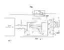
FIG. 1 is a circuit diagram illustrating a PWM controller according to an exemplary embodiment of the present invention;
FIG. 2 is a graph illustrating current flowing through the PWM controller; and
FIG. 3 is a circuit diagram illustrating a conventional PWM controller.
DETAILED DESCRIPTION
Hereinafter, a PWM controller according to embodiments of the present invention will be described in detail with reference to the attached drawings.
It is understood that the tem “vehicle” or “vehicular” or other similar term as used herein is inclusive of motor vehicles in general such as passenger automobiles including sports utility vehicles (SUV), buses, trucks, various commercial vehicles, watercraft including a variety of boats and ships, aircraft, and the like, and includes hybrid vehicles, electric vehicles, combustion, plug-in hybrid electric vehicles, hydrogen-powered vehicles and other alternative fuel vehicles (e.g. fuels derived from resources other than petroleum).
Furthermore, the control logic of the present invention may be embodied as non-transitory computer readable media on a computer readable medium containing executable program instructions executed by a processor, controller or the like. Examples of the computer readable mediums include, but are not limited to, ROM, RAM, compact disc (CD)-ROMs, magnetic tapes, floppy disks, flash drives, smart cards and optical data storage devices. The computer readable recording medium can also be distributed in network coupled computer systems so that the computer readable media is stored and executed in a distributed fashion, e.g., by a telematics server or a Controller Area Network (CAN).
FIG. 1 is a circuit diagram illustrating a PWM controller according to an exemplary embodiment of the present invention. The PWM controller of the present invention includes a plurality of Field Effect Transistors (FETs) and an FET driver 500, a comparator 400, and a microcomputer 200. The comparator 400 compares a current flowing through the FETs with an overcurrent reference value. The microcomputer 200 controls a motor M and a circuit protection function, and turns off the FET driver 500 when the current flowing through the FETs is greater than the overcurrent reference value as a result of the comparison by the comparator 400.
Generally, in the case of a Metal-Oxide-Semiconductor Field-Effect Transistor (MOS FET), a diode component is structurally present in a direction from a source to a drain when the MOS FET is operated at high frequency. Therefore, when a switching element is implemented as a MOS FET, a diode that typically is required to be connected in parallel to the switching element may be omitted, thus simplifying the construction of the circuit. Further, when an FET is turned on, the drain (load) and the source thereof are electrically connected to each other, so that current may flow bidirectionally. However, when the FET is turned off, current cannot flow from the drain to the source. Current can, however, flow through a parasitic diode from the source to the drain.
The present invention can be applied to the MOS FET, and is intended to prevent the disconnection of a circuit from occurring when, as in the circuit shown in the drawing, a short (case A) occurs between both terminals M+ and M− of the motor M and a short (case B) occurs between the negative terminal M− of the motor M and the bias voltage terminal VS of a battery.
Conventionally, a separate high-capacity FET is typically provided and is used to implement a protection circuit. However, in the present invention, the comparator 400 for comparing the current flowing through the FETs with the overcurrent reference value is set instead, and the microcomputer 200 controls the motor M and the circuit protection function. In this case, a pre-FET driver is set to turn off the FET driver 500 when the current flowing through the FETs is greater than the overcurrent reference value as a result of the comparison by the comparator 400, thus performing a protection function.
As shown in FIG. 2, each FET has a tendency for a current to increase as the duty ratio of the FET increases, and the current corresponding to a predetermined level has a threshold level as an overcurrent. Therefore, when such an overcurrent is initially detected and a signal is interrupted using the characteristics of the FET, the circuit may be protected when shorts corresponding to the illustrated case occur.
In detail, as shown in FIG. 1, the plurality of FETs according to the present invention may be composed of a low-side FET L and a high-side FET H, and the motor M may be operated in response to the ON/OFF operations of the low-side FET L. Further, since current flows through a shunt resistor only when the low-side FET L is turned on, the current flows into the comparator 400 at that time. Meanwhile, the high-side FET H is an FET functioning to form a pass through which energy flows into the motor M when the low-side FET L is turned off (that is, during an interval in which power is not applied to the motor M so as to control the speed of the motor M). In some cases, the high-side FET H may be implemented as a diode for the sake of cost reduction, ease of control, etc. Unless this pass is formed, a high reverse voltage may be induced in the motor M and then the low-side FET L may be broken down when the low-side FET L is turned off. Accordingly, the overcurrent reference value for the comparator 400 may be set based on the capacity of the low-side FET L.
When both the terminals M+ and M− of the motor M are short circuited, the comparator 400 determines that current flowing through the low-side FET L is greater than the overcurrent reference value. Alternatively, when the negative terminal M− of the motor M and the bias voltage terminal VS of the battery are short circuited, the comparator 400 also determines that the current flowing through the low-side FET L is greater than the overcurrent reference value.
The above described functions may also be performed by another exemplary embodiment of the present invention. A PWM controller according to another embodiment of the present invention includes a plurality of FETs and an FET driver 500, a comparator 400, a microcomputer 200, and a switch 300. The comparator 400 compares a current flowing through the FETs with an overcurrent reference value. The microcomputer 200 performs a motor control function and a circuit protection function. Finally, the switch 300 cuts off a connection between the microcomputer and the FET driver when the current flowing through the FETs is greater than the overcurrent reference value as a result of the comparison by the comparator.
In this case, the switch 300 is configured to cut off the connection between the microcomputer and the FET driver when the current flowing through the FETs is greater than the overcurrent reference value as a result of the comparison by the comparator, thus protecting the circuit by disconnecting the microcomputer from the FET driver.
Further, the PWM controller of the present invention may set the overcurrent reference value for the comparator 400 based which FET has the largest capacity, thus enabling the protection function to be more stably and conservatively implemented.
Furthermore, the comparator 400 may enable a separate high-capacity FET to be omitted by determining that the current flowing through the FETs is greater than the overcurrent reference value when both terminals M+ and M− of the motor M are short circuited, or by determining that the current flowing through the FETs is greater than the overcurrent reference value when the negative terminal M− of the motor M and the bias voltage terminal VS of the battery are short circuited.
Meanwhile, the PWM controller of the present invention may incidentally implement a protection function even when any one of the following short circuiting events occur:
(1) A PWM/Diagnosis short: a PWM/Diagnosis short occurs when a PWM signal from a main controller is input as a Diagnosis signal to the main controller, so that the main controller can determine that a PWM signal line and a Diagnosis signal line have been short circuited.
(2) A PWM/Vbatt(VS) short: when a PWM signal line and a Vbatt line are short circuited, the input of the PWM controller always has a duty ratio of 0%. In this case, since the duty ratio is always 0%, the PWM controller is not damaged, and it can be sensed that an abnormality has occurred in the motor.
(3) A PWM/GND short: in this case, the input of the PWM controller always has a duty ratio of 100%, the PWM controller is not damaged, and the motor always moves at the highest speed, and thus it can be sensed that an abnormality has occurred in the motor.
(4) A PWM/M+ short: this case is identical to that of the PWM/Vbatt short.
(5) A Diagnosis/Vbatt short: in this case, a Diagnosis signal always has a duty ratio of 0%. When the protection function of the PWM controller, such as protection against overvoltage, overcurrent, low voltage or high temperature, is operated, the main controller cannot receive a Diagnosis signal, and thus the main controller cannot determine whether the PWM controller is defective. However, since the motor is not moving due to the operation of the protection function of the PWM controller, whether an abnormality has occurred may be sensed. As a result, damage does not occur in the PWM controller.
(6) A Diagnosis/GND short: in this case, since a Diagnosis signal always has a duty ratio of 100% (low), the main controller may sense whether an abnormality has occurred, and then stop the PWM controller accordingly.
(7) A Diagnosis/M+ short: this case is identical to that of the Diagnosis/Vbatt short.
(8) A Diagnosis/M− short: in this case, the voltage level of the M− terminal is the inverse of a PWM input signal. When the voltage of the M− terminal is input as a Diagnosis signal to the main controller, the main controller may determine that an abnormality has occurred in the PWM controller. In this case, the PWM controller is not damaged, and it can be determined whether an abnormality has occurred in the motor.
(9) A Vbatt(VS)/GND short: in this case, the PWM controller is not damaged, but a fuse melts due to the short that occurred at the power terminal.
Accordingly, the above described PWM controller(s) having the above-described construction protect power terminals or signal lines against the short circuiting that may occur in a motor controller without requiring a separate element to do so, thus decreasing the price of the motor controller and improving the reliability of the motor controller.
Although the preferred embodiments of the present invention have been disclosed for illustrative purposes, those skilled in the art will appreciate that various modifications, additions and substitutions are possible, without departing from the scope and spirit of the invention as disclosed in the accompanying claims.
Claims
What is claimed is:1. A Pulse Width Modulation (PWM) controller, comprising:
a plurality of Field Effect Transistors (FETs) and an FET driver;
a comparator configured to compare a current flowing through the FETs with an overcurrent reference value; and
a microcomputer configured to control a motor and a circuit protection function, and selectively turn off the FET driver when the current flowing through the FETs is greater than the overcurrent reference value as a result of the comparison by the comparator.
2. The PWM controller according to claim 1, wherein the overcurrent reference value for the comparator is set based on which of FET of the plurality of FETs has a largest capacity.
3. The PWM controller according to claim 1, wherein the comparator is configured to determine that the current flowing through the FETs is greater than the overcurrent reference value when both terminals of the motor are short circuited.
4. The PWM controller according to claim 1, wherein the comparator is configured to determine that the current flowing through the FETs is greater than the overcurrent reference value when a negative terminal of the motor and a bias voltage terminal of a battery are short circuited.
5. The PWM controller according to claim 1, wherein the plurality of FETs comprise a low-side FET and a high-side FET.
6. The PWM controller according to claim 5, wherein the overcurrent reference value for the comparator is set based on a capacity of the low-side FET.
7. The PWM controller according to claim 6, wherein the comparator is configured to determine that current flowing through the low-side FET is greater than the overcurrent reference value when both terminals of the motor are short circuited.
8. The PWM controller according to claim 6, wherein the comparator is configured to determine that current flowing through the low-side FET is greater than the overcurrent reference value when a negative terminal of the motor and a bias voltage terminal of a battery are short circuited.
9. A Pulse Width Modulation (PWM) controller, comprising:
a plurality of Field Effect Transistors (FETs) and an FET driver;
a comparator configured to compare a current flowing through the FETs with an overcurrent reference value;
a microcomputer configured to control a motor and a circuit protection function; and
a switch configured to cut off a connection between the microcomputer and the FET driver when the current flowing through the FETs is greater than the overcurrent reference value as a result of comparison by the comparator.
10. The PWM controller according to claim 9, wherein the overcurrent reference value for the comparator is set based on which of FET of the plurality of FETs has a largest capacity.
11. The PWM controller according to claim 9, wherein the comparator is configured to determine that the current flowing through the FETs greater than the overcurrent reference value when both terminals of the motor are short circuited.
12. The PWM controller according to claim 9, wherein the comparator is configured to determine that the current flowing through the FETs greater than the overcurrent reference value when a negative terminal of the motor and a bias voltage terminal of a battery are short circuited.
13. The PWM controller according to claim 9, wherein the plurality of FETs comprise a low-side FET and a high-side FET.
14. The PWM controller according to claim 13, wherein the overcurrent reference value for the comparator is set based on a capacity of the low-side FET.
15. The PWM controller according to claim 14, wherein the comparator is configured to determine that current flowing through the low-side FET is greater than the overcurrent reference value when both terminals of the motor are short circuited.
16. The PWM controller according to claim 14, wherein the comparator is configured to determine that current flowing through the low-side FET is greater than the overcurrent reference value when a negative terminal of the motor and a bias voltage terminal of a battery are short circuited.
17. A non-transitory computer readable medium containing program instructions executed by a PWM controller, the computer readable medium comprising:
program instructions that compare a current flowing through a plurality of Field Effect Transistors (FETs) with an overcurrent reference value;
program instructions that control a motor and a circuit protection function; and
program instructions that selectively turn off a FET driver when the current flowing through the plurality of FETs is greater than the overcurrent reference value as a result of the comparison.
18. The non-transitory computer readable medium according to claim 17, wherein the overcurrent reference value for the comparator is set based on which of FET of the plurality of FETs has a largest capacity.
19. The non-transitory computer readable medium according to claim 17, further comprising program instructions that determine that the current flowing through the FETs is greater than the overcurrent reference value when both terminals of the motor are short circuited.
20. The non-transitory computer readable medium according to claim 17, further comprising program instructions that determine that the current flowing through the FETs is greater than the overcurrent reference value when a negative terminal of the motor and a bias voltage terminal of a battery are short circuited.
Images & Drawings included:


Sources:
- United States Patent and Trademark Office - verify current appl. status at the USPTO↗
Similar patent applications:
- » 20210036693
Pulse width modulation control circuit and control method of pulse width modulation signal - » 20130009719
PULSE WIDTH MODULATION CONTROLLER AND PULSE WAVEFORM CONTROL METHOD - » 20090296805
Pulse width modulation controller and pulse waveform control method - » 20080180381
PULSE WIDTH MODULATION DIMMING CONTROL METHOD AND DISPLAY APPARATUS HAVING PULSE WIDTH MODULATION DIMMING CONTROL FUNCTION - » 20130258735
Method and control unit for the pulse-width-modulated control of switching elements of a pulse-controlled inverter - » 20050134244
Pulse width modulation controller with double pulse immunity - » 20170317620
Vehicle with controller for performing pulse width modulation control - » 20190356213
Control circuit for outputting pulse width modulation control signal with zero-crossing detection - » 20200014296
Control circuit and control method for outputting pulse width modulation control signal with zero-crossing detection - » 20100141032
Control unit and method for pulse width modulated control
Recent applications in this class:
- » 20240364097 2024-10-31
ELECTRIC WORK MACHINE - » 20230335985 2023-10-19
MOBILE APPLICATION WITH COMBINED BREAKER AND RELAY - » 20220393458 2022-12-08
Protection apparatus for a load resistor, and method for operating such a protection apparatus - » 20220006285 2022-01-06
Coolant fitting promoting turbulent flow - » 20220006284 2022-01-06
Inverter assembly with integrated coolant coupling port - » 20220006283 2022-01-06
Coolant connector having a chamfered lip and fir tree axially aligned with at least one o-ring - » 20210218242 2021-07-15
System, method, and apparatus for multi-port power converter and inverter assembly - » 20210184455 2021-06-17
System, method, and apparatus for power distribution in an electric mobile application using a combined breaker and relay - » 20210111552 2021-04-15
SYSTEM, METHOD, AND APPARATUS FOR POWER DISTRIBUTION IN AN ELECTRIC MOBILE APPLICATION USING A COMBINED BREAKER AND RELAY - » 20210083470 2021-03-18
System, method, and apparatus for power distribution in an electric mobile application using a combined breaker and relay
Recent applications for this Assignee:
- » 20250293967 2025-09-18
VEHICLE CONTROL APPARATUS AND METHOD THEREOF - » 20250293557 2025-09-18
MOTOR WITH A COOLING STRUCTURE - » 20250293373 2025-09-18
BATTERY ASSEMBLY - » 20250293361 2025-09-18
FUEL CELL POWER GENERATION MODULE - » 20250293308 2025-09-18
ELECTRODE ASSEMBLY AND ALL-SOLID STATE BATTERY INCLUDING THE SAME - » 20250292638 2025-09-18
SYSTEM AND METHOD FOR MONITORING POWER OF A VEHICLE - » 20250292590 2025-09-18
METHOD AND APPARATUS FOR CONTEXT-RECOGNITION OBJECT ACTION PREDICTION AND PATH PLANNING FOR AUTONOMOUS VEHICLES BASED ON PEDESTRIAN MOTION PREDICTION - » 20250290600 2025-09-18
PRESSURE VESSEL - » 20250289441 2025-09-18
METHOD AND APPARATUS FOR CALIBRATING ORIENTATION ANGLE OF VEHICLE SENSOR - » 20250289422 2025-09-18
SYSTEM AND METHOD FOR GENERATING EMERGENCY COLLISION AVOIDANCE STRATEGY FOR A VEHICLE