Joining method of composite parts having a thermoset matrix, and wind turbine blade manufactured using this said method
US20130189112A1
2013-07-25
13/520,972
2011-01-07
✅ Patent granted
US 10,179,359 B2
2019-01-15
WO; PCT/DK2011/050005; 20110107
WO; WO2011/085730; 20110721
Audrey K Bradley | Anthony Ayala Delgado
Wood Herron & Evans LLP
2034-01-30
Abstract:
A method of fabricating a composite joint from a first cured composite component (13) and a second cured composite component (14), the first and second cured composite components (13, 14) comprising fibre elements embedded in a thermoset resin matrix; the method comprising the steps of providing an adhesive (15) on at least one of the first and/or second composite components (13, 14); forming a joint region between the first and second composite component by bringing the first and second composite component into contact with each other with the adhesive (15) therebetween; applying a force to the joint region (16, 17); and heating the first composite component in the joint region to a temperature above the glass transition temperature of the thermoset resin matrix of the first composite component.
Inventors:
- Andrew Hedges 4 🇬🇧 London, United Kingdom
- Kim Sylvester Nielsen 1 🇩🇰 Longborg, Denmark
- Andrew Hedges 5 🇬🇧 Southampton, United Kingdom
- Kim Sylvester Nielsen 1 🇩🇰 Tarm, Denmark
Assignee:
- Vestas Wind Systems A/S 1,341 🇩🇰 Aarhus N, Denmark
- VESTAS WIND SYSTEMS A/S 73 🇩🇰 Aarhus, Denmark
Applicant:
Interested in similar patents?
Get notified when new applications in this technology area are published.
Classification:
F03D3/06 IPC
Wind motors with rotation axis substantially perpendicular to the air flow entering the rotor Rotors
F03D3/062 » CPC further
Wind motors with rotation axis substantially perpendicular to the air flow entering the rotor ; Rotors Construction
B21D53/78 » CPC main
Making other particular articles propeller blades; turbine blades
B29C65/00 IPC
Joining of preformed parts ; Apparatus therefor
B29C66/1122 » CPC further
General aspects of processes or apparatus for joining preformed parts; General aspects dealing with the joint area or with the area to be joined; Particular design of joint configurations particular design of the joint cross-sections; Joint cross-sections comprising a single joint-segment, i.e. one of the parts to be joined comprising a single joint-segment in the joint cross-section; Single lapped joints Single lap to lap joints, i.e. overlap joints
B29C66/71 » CPC further
General aspects of processes or apparatus for joining preformed parts characterised by the composition, physical properties or the structure of the material of the parts to be joined; Joining with non-plastics material characterised by the composition of the plastics material of the parts to be joined
B29C66/4326 » CPC further
General aspects of processes or apparatus for joining preformed parts; General aspects of joining substantially flat articles, e.g. plates, sheets or web-like materials; Making flat seams in tubular or hollow articles; Joining single elements to substantially flat surfaces; Joining substantially flat articles ; Making flat seams in tubular or hollow articles; Joining a relatively small portion of the surface of said articles for making tubular articles or closed loops, e.g. by joining several sheets ; for making hollow articles or hollow preforms for making hollow articles or hollow-preforms, e.g. half-shells
B29C66/54 » CPC further
General aspects of processes or apparatus for joining preformed parts; General aspects of joining tubular articles; General aspects of joining long products, i.e. bars or profiled elements; General aspects of joining single elements to tubular articles, hollow articles or bars; General aspects of joining several hollow-preforms to form hollow or tubular articles; Joining tubular articles, profiled elements or bars; Joining single elements to tubular articles, hollow articles or bars; Joining several hollow-preforms to form hollow or tubular articles Joining several hollow-preforms, e.g. half-shells, to form hollow articles, e.g. for making balls, containers; Joining several hollow-preforms, e.g. half-cylinders, to form tubular articles
B29C66/721 » CPC further
General aspects of processes or apparatus for joining preformed parts characterised by the composition, physical properties or the structure of the material of the parts to be joined; Joining with non-plastics material characterised by the structure of the material of the parts to be joined Fibre-reinforced materials
B29C66/73118 » CPC further
General aspects of processes or apparatus for joining preformed parts characterised by the composition, physical properties or the structure of the material of the parts to be joined; Joining with non-plastics material characterised by the intensive physical properties of the material of the parts to be joined, by the optical properties of the material of the parts to be joined, by the extensive physical properties of the parts to be joined, by the state of the material of the parts to be joined or by the material of the parts to be joined being a thermoplastic or a thermoset characterised by the intensive physical properties of the material of the parts to be joined; Thermal properties; Tg, i.e. glass transition temperature of different glass transition temperature, i.e. the glass transition temperature of one of the parts to be joined being different from the glass transition temperature of the other part
B29C66/73756 » CPC further
General aspects of processes or apparatus for joining preformed parts characterised by the composition, physical properties or the structure of the material of the parts to be joined; Joining with non-plastics material characterised by the intensive physical properties of the material of the parts to be joined, by the optical properties of the material of the parts to be joined, by the extensive physical properties of the parts to be joined, by the state of the material of the parts to be joined or by the material of the parts to be joined being a thermoplastic or a thermoset characterised by the state of the material of the parts to be joined uncured, partially cured or fully cured the to-be-joined area of at least one of the parts to be joined being fully cured, i.e. fully cross-linked, fully vulcanized the to-be-joined areas of both parts to be joined being fully cured
B29C66/73941 » CPC further
General aspects of processes or apparatus for joining preformed parts characterised by the composition, physical properties or the structure of the material of the parts to be joined; Joining with non-plastics material characterised by the intensive physical properties of the material of the parts to be joined, by the optical properties of the material of the parts to be joined, by the extensive physical properties of the parts to be joined, by the state of the material of the parts to be joined or by the material of the parts to be joined being a thermoplastic or a thermoset characterised by the material of the parts to be joined being a thermoplastic or a thermoset characterised by the material of at least one of the parts being a thermoset characterised by the materials of both parts being thermosets
B29C66/91411 » CPC further
General aspects of processes or apparatus for joining preformed parts; Measuring or controlling the joining process by measuring or controlling the temperature, the heat or the thermal flux by controlling or regulating the temperature, the heat or the thermal flux by controlling or regulating the temperature of the parts to be joined, e.g. the joining process taking the temperature of the parts to be joined into account
F03D1/0675 » CPC further
Wind motors with rotation axis substantially parallel to the air flow entering the rotor ; Rotors characterised by their construction, i.e. structural design details of the blades
B29C66/7212 » CPC further
General aspects of processes or apparatus for joining preformed parts characterised by the composition, physical properties or the structure of the material of the parts to be joined; Joining with non-plastics material characterised by the structure of the material of the parts to be joined; Fibre-reinforced materials characterised by the composition of the fibres
B29C66/919 » CPC further
General aspects of processes or apparatus for joining preformed parts; Measuring or controlling the joining process by measuring or controlling the temperature, the heat or the thermal flux characterised by specific temperature, heat or thermal flux values or ranges
B29C66/91413 » CPC further
General aspects of processes or apparatus for joining preformed parts; Measuring or controlling the joining process by measuring or controlling the temperature, the heat or the thermal flux by controlling or regulating the temperature, the heat or the thermal flux by controlling or regulating the temperature of the parts to be joined, e.g. the joining process taking the temperature of the parts to be joined into account the parts to be joined having different temperatures
B29K2101/10 » CPC further
Use of unspecified macromolecular compounds as moulding material Thermosetting resins
B29K2105/06 » CPC further
Condition, form or state of moulded material or of the material to be shaped containing reinforcements, fillers or inserts
B29K2105/24 » CPC further
Condition, form or state of moulded material or of the material to be shaped crosslinked or vulcanised
B29L2031/082 » CPC further
Other particular articles; Blades for rotors, stators, fans, turbines or the like, e.g. screw propellers Blades, e.g. for helicopters
B29L2031/085 » CPC further
Other particular articles; Blades for rotors, stators, fans, turbines or the like, e.g. screw propellers; Blades, e.g. for helicopters Wind turbine blades
Y10T29/49336 » CPC further
Metal working; Method of mechanical manufacture; Impeller making Blade making
F01D5/14 IPC
Blades; Blade-carrying members ; Heating, heat-insulating, cooling or antivibration means on the blades or the members; Blades Form or construction
B29C65/48 » CPC further
Joining of preformed parts ; Apparatus therefor using adhesives, i.e. using supplementary joining material; solvent bonding
F03D1/06 IPC
Wind motors with rotation axis substantially parallel to the air flow entering the rotor Rotors
B29C66/73754 » CPC further
General aspects of processes or apparatus for joining preformed parts characterised by the composition, physical properties or the structure of the material of the parts to be joined; Joining with non-plastics material characterised by the intensive physical properties of the material of the parts to be joined, by the optical properties of the material of the parts to be joined, by the extensive physical properties of the parts to be joined, by the state of the material of the parts to be joined or by the material of the parts to be joined being a thermoplastic or a thermoset characterised by the state of the material of the parts to be joined uncured, partially cured or fully cured the to-be-joined area of at least one of the parts to be joined being partially cured, i.e. partially cross-linked, partially vulcanized the to-be-joined areas of both parts to be joined being partially cured
B29C65/10 » CPC further
Joining of preformed parts ; Apparatus therefor by heating, with or without pressure using hot gases (e.g. combustion gases) or flames coming in contact with at least one of the parts to be joined
Description
The present invention relates to a method of joining two composite components together. In particular, the present invention relates to joining two composite components together such that stress concentrations are minimised or avoided in the joint region.
When large composite components, such as those components used in the manufacture of wind turbine blades are assembled, there is often the problem that stress concentrations can be created in the joint region. For example, in a wind turbine blade, the structural spar section may be up to 50 m in length and have a width of up to 2 metres. Such a spar may be formed in a box configuration from four components, two spar caps separated by two shear webs. The individual composite components are pre-made, that is they are cured composite components and therefore stiff.
Due to the large size of the composite components involved, each individual composite component can be difficult and expensive to mould accurately enough for future accurate assembly. For instance, in a manufacturing plant having a production line, many moulds may be used to fabricate the same composite component. However, there may be variations between the different moulds such that when the composite components are to be assembled they are not all identical. This can result in a less accurate fit at a joint, with variations in three spatial dimensions.
It is known in the prior art to overcome the above issues by filling up the gaps between the composite components to be joined by using an adhesive as a filler. However, this process results in an unpredictable adhesive usage which may result in the joint having a reduced strength.
It is also known in the prior art to assemble the composite components together and apply a clamping force so that the components are forced together. The clamping force removes any gaps that may exist between the two components and thus results in uniform adhesive usage. However, this approach creates a preload at the joint as each composite component will tend to try to deform to its original shape. These preloads result in residual stresses which may structurally weaken the joint.
It is an aim of the present invention to create a composite joint which does not create residual stresses and which can have a uniform and pre-determined adhesive usage.
According to the present invention there is provided a method of fabricating a composite joint from a first cured composite component and a second cured composite component, the first and second cured composite components comprising fibre elements embedded in a thermoset resin matrix; the method comprising the steps of:
providing an adhesive on at least one of the first and/or second composite components;
forming a joint region between the first and second composite components by bringing the first and second composite component into contact with each other with the adhesive therebetween;
applying a force to the joint region; and
heating the first composite component in the joint region to a temperature above the glass transition temperature of the thermoset resin matrix of the first composite component.
The step of heating the first composite component to a temperature above the glass transition temperature of the thermoset resin matrix of the first composite component reduces the stiffness of the first composite component. Accordingly, when the two composite components are brought together under a force, the first composite component may deform slightly to account for any variations in fit between the two composite components. As the heating of the first composite component takes place above the glass transition temperature, any stress concentrations are minimised or avoided.
Furthermore, as the two composite components will now be joined together with no variations in fit, a predetermined amount of adhesive can be used for the joint. This is important in keeping a consistent level of quality and lack of variation between many fabricated joints.
A thermoset resin matrix is formed from network-forming polymers. When the resin is cured, which may be under heat and vacuum, the resin undergoes an increase in viscosity and the polymer chains cross link and set, such that the resin can no longer flow. This change is not reversible. After curing the composite part, the thermoset resin has a characteristic glass transition temperature. If the composite component is heated to above this temperature, the component will soften. The component will not melt on further heating, it will instead deteriorate if the applied temperatures are too high. The glass transition temperature may be established by use of the dynamic mechanical thermal analysis (DMTA) method.
In use, the temperature applied may be up to 70 degrees centigrade higher than the glass transition temperature of the thermoset matrix. However, the applied temperature should be lower than the temperature where thermal degradation of the composite occurs.
The step of applying a force to the joint region encompasses any means by which the two composite components can be brought together. In a particular example, this may be a clamp.
The method may further comprise the step of heating the second composite component in the joint region to a temperature above the glass transition temperature of the thermoset resin matrix of the second composite component. By heating both composite components to above the glass transition temperature allows both composite components to deform slightly so that any variations in fit between the two components are minimised.
A spar for a wind turbine blade may be provided with the spar comprising a composite joint fabricated according to the method described above.
A wind turbine blade comprising the spar may be provided.
A wind turbine may be provided having at least one wind turbine blade as described above. Such a wind turbine may be a horizontal axis three bladed turbine of the type known as the “Danish design”.
The invention will now be described by way of example only, with reference to the following Figures in which:
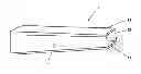
FIG. 1 is a perspective view of a spar for a wind turbine blade.
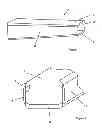
FIG. 2 is a cross sectional view of a spar for a wind turbine blade.
FIG. 3 is a schematic view of a joint according to an example of the present invention.
FIG. 1 shows a spar 10 for a wind turbine blade (not shown). Although the invention is applicable to the joining of any two cured composite parts, this example is described with reference to a wind turbine blade component. The spar 10 is a structural member that extends along the length of a wind turbine blade from a root end of the blade to a tip end of the blade. In use, an aerodynamic shell is fixed to the spar to create the wind turbine blade.
The spar 10 comprises two spar caps 11 and two shear webs 12 arranged in a box shape. The spar caps 11 are fixed to the aerodynamic shells (not shown) and the shear webs 12 maintain the distance between the two spar caps.
The spar caps 11 and the shear webs 12 are pre-manufactured in a mould prior to being assembled into the spar 10. In this example, the spar caps 11 are formed from carbon fibre embedded in a thermoset resin matrix and the shear webs 12 are formed from glass fibre embedded in a thermoset resin matrix. The spar caps 11 and the shear webs 12 are fabricated in a mould and then cured so that they are solid components prior to being assembled into the spar 10. The fabrication of the spar caps 11 and the shear webs 12 can be done by any well known composite manufacturing method known in the art, i.e. using prepreg technology or resin infusion.
As shown in FIG. 2, the shear webs 12 are fixed to the spar caps 11 in a joint region “J” which extends along the length of the spar. Owing to the large size of the spar caps 11 and the shear webs 12, which may be up to 50 m in length, there may be variations in the fits of the components when they are assembled as described above, which may create stress concentrations in the joint region “J”.
FIG. 3 shows a schematic view of a joint region according to the invention. In this example, a first cured composite component 13 is being joined to a second cured composite component 14. Due to the manufacture of the composite components 13, 14, there are variations in fit between the two parts as can be seen in an exaggerated form in FIG. 3.
The first and second component 13, 14 are arranged next to each other in the joint region and a predetermined amount of adhesive 15 is placed between them. The adhesive may be, for example, epoxy or polyurethane. The joint is formed by applying heat and pressure at the joint region as indicated by the arrows 16 and 17.
By heating the composite component to above the glass transition temperature (Tg) of the thermoset matrix allows the stiffness of the composite component to reduce. This results in a reduced force required to fit the two composite components together. When the composite component is heated to above the glass transition temperature of the thermoset matrix, the polymer chains of the thermoset resin are allowed to move, which relaxes the preloads caused by the pressure required to force the composite components 13, 15 together. This results in a reduced likelihood of a stress concentration and allows a predetermined amount of adhesive to be used.
In this embodiment, the first composite component 13 is a cured spar cap formed from carbon fibre embedded in a matrix of epoxy resin which has a Tg of 130 degrees centigrade, and the second composite component 14 is a cured shear web formed from glass fibre embedded in a matrix of epoxy resin which has a Tg of 60 degrees centigrade.
In a first example, the second cured composite component 14 is heated to above the glass transition temperature of the thermoset resin of the second composite component 14. Heat is applied as indicated at 17 at a temperature of 70 degrees centigrade. The heat may be applied from a hot air blower or a heat mat. The application of heat reduces the stiffness of the second composite component 14 which results in a reduced force required to fit the two composite components together as described above.
In a second example, both composite components 13, 14 are heated to above the glass transition temperature of the thermoset resin of each composite component. Heat is applied as indicated at 16 at a temperature of 140 degrees centigrade and heat is applied as indicated at 17 at a temperature of 70 degrees centigrade. In this example, the stiffness of both composite components will be reduced and the clamps, which force the components 13, 14 together may determine the final shape of the joint.
In a third example, heat is applied only as indicated at 16 at a temperature of 140 degrees and the heat will transfer from the first composite component 13 to the second composite component 14. As the applied heat is at a temperature higher than the Tg of both thermoset resins of each composite component, the stiffness of both composite components will be reduced.
Claims
1. A method of fabricating a composite joint from a first cured composite component and a second cured composite component, the first and second cured composite components comprising fibre elements embedded in a thermoset resin matrix; the method comprising:
providing an adhesive on at least one of the first and second composite components;
forming a joint region between the first and second composite components by bringing the first and second composite component into contact with each other with the adhesive therebetween;
applying a force to the joint region; and
heating the first composite component in the joint region to a temperature above the glass transition temperature of the thermoset resin matrix of the first composite component.
2. A method of fabricating a composite joint in accordance with claim 1, further comprising heating the second composite component in the joint region to a temperature above the glass transition temperature of the thermoset resin matrix of the second composite component.
3. A spar for a wind turbine blade, the spar comprising a composite joint fabricated according to the method of claim 1.
4. A wind turbine blade comprising a spar according to claim 3.
5. A wind turbine having at least one wind turbine blade according to claim 4.
Images & Drawings included:

Sources:
- United States Patent and Trademark Office - verify current appl. status at the USPTO↗
Recent applications in this class:
- » 20200368805 2020-11-26
Assembly and method of forming gas turbine engine components - » 20200001347 2020-01-02
Bond fixture for composite splice fairing assembly - » 20190143396 2019-05-16
CORE FOR HIGH-TEMPERATURE SHAPING OF A METAL PART AND MANUFACTURING PROCESS - » 20180043418 2018-02-15
Bond fixture composite splice fairing assembly - » 20160199902 2016-07-14
Method for the high-temperature shaping of a metal blade reinforcement - » 20140208819 2014-07-31
Device for shaping a metal sheet by die stamping - » 20140101939 2014-04-17
Method of fabricating integrally bladed rotor and stator vane assembly - » 20130333213 2013-12-19
Method of using laser shock impacts to produce raised elements on a wall surface capable of being swept by a fluid in order to control the intensity of turbulence in a transition zone - » 20110274555 2011-11-10
Production method of leading edge reinforcement of fan blade - » 20110274551 2011-11-10
Production method of leading edge reinforcement of fan blade
Recent applications for this Assignee:
- » 20250250967 2025-08-07
MODULAR NACELLE OF A WIND TURBINE HAVING A LIQUID SPILLAGE CONTAINMENT SYSTEM AND RELATED METHOD - » 20250223946 2025-07-10
TRANSMISSION FOR A WIND TURBINE - » 20250205976 2025-06-26
WIND TURBINE BLADE - » 20250205976 2025-06-26
WIND TURBINE BLADE - » 20250198385 2025-06-19
TRANSITION PIECE FOR A HYBRID WIND TURBINE TOWER AND METHOD FOR ASSEMBLING SAME - » 20250188908 2025-06-12
METHOD AND A KIT FOR INSTALLING AT LEAST ONE DAMPER UNIT IN A TOWER SECTION OF A WIND TURBINE - » 20250188903 2025-06-12
METHOD FOR REDUCING GEAR INDUCED NOISE FROM A WIND TURBINE - » 20250179988 2025-06-05
A NACELLE FOR A WIND TURBINE - » 20250163887 2025-05-22
METHOD OF CONTROLLING TONAL NOISE FROM A WIND TURBINE - » 20250137440 2025-05-01
Method of servicing a wind turbine rotor blade