Implant
US20130337409A1
2013-12-19
13/916,175
2013-06-12
✅ Patent granted
US 9,597,167 B2
2017-03-21
-
-
Chris L Rodriguez | Hao D Mai
Buchanan Ingersoll & Rooney PC
2033-06-12
Abstract:
The present disclopsure relates to an implant, such as a dental implant, having a base member and a thread arranged at an outer end of the base member. The dental implant can be easily inserted and good footing of the implant in the bone can be achieved. Annular ridges and/or recesses can be formed in a section of the base member having no thread.
Assignee:
- Lakeview Innovation Ltd. 14 🇨🇭 Buochs, Switzerland
Applicant:
Interested in similar patents?
Get notified when new applications in this technology area are published.
Classification:
A61C8/0025 » CPC main
Means to be fixed to the jaw-bone for consolidating natural teeth or for fixing dental prostheses thereon; Dental implants; Implanting tools characterised by the shape; Self-screwing with multiple threads
A61C8/00 IPC
Means to be fixed to the jaw-bone for consolidating natural teeth or for fixing dental prostheses thereon; Dental implants; Implanting tools
A61C8/0018 » CPC further
Means to be fixed to the jaw-bone for consolidating natural teeth or for fixing dental prostheses thereon; Dental implants; Implanting tools characterised by the shape
A61C8/0037 » CPC further
Means to be fixed to the jaw-bone for consolidating natural teeth or for fixing dental prostheses thereon; Dental implants; Implanting tools characterised by the shape Details of the shape
A61C8/0012 » CPC further
Means to be fixed to the jaw-bone for consolidating natural teeth or for fixing dental prostheses thereon; Dental implants; Implanting tools characterised by the material or composition, e.g. ceramics, surface layer, metal alloy
A61C8/0022 » CPC further
Means to be fixed to the jaw-bone for consolidating natural teeth or for fixing dental prostheses thereon; Dental implants; Implanting tools characterised by the shape Self-screwing
Description
The present invention relates to an implant, in particular to a dental implant, having a base member and a thread arranged at an outer end of the base member, where in the region of the base member having no thread, annular ridges and/or recesses are formed.
The use of implants for repairing damage to bones, joints or teeth has long been known. For example, implantable screws or implantable connectors are used to stabilize broken bones or for artificial joints. Even with total loss of one or more teeth, it is now common practice to recommend a dental implant. In this, a base member of the implant is anchored in the jaw, the superstructure, for example a bridge or a crown, can then be fitted onto the base member using different aids.
For example WO 2007/090529 A1 describes a implant intended to grow into a bone. The implant comprises an implant member, an implant post and a superstructure. In order to properly anchor the implant member in the jaw bone, the implant member is provided with a thread which extends across the entire length of the implant member. After the implant member has grown into the jaw bone, the implant post is attached to the implant member, the superstructure is fitted onto the implant post.
A disadvantage of this implant is that the implant is attached in the bone with the screw thread extending the full length of the implant member. For this purpose, boring a hole and cutting a thread in the bone is required. Precise insertion is therefore difficult. In particular, screwing-in is in practice tedious and challenging when space is limited.
Implants are also known that are fixed in the jaw using a press fit. Such a press fit, however, is not particularly advantageous due to the pressure on the bone and the lack of precision.
DE 197 18 175 A1 shows a further dental implant comprising a base member implantable in the jaw bone. This implant is based on the object of providing stable anchorage of the base member with small damage to the bone tissue of the patient. For this purpose, it is provided that the base member at its inner end, i.e. the end first inserted in the jaw bone, comprises a first section, to which a second section connects in which the outer diameter increases in the direction towards the outer end of the implant base member. This second section is followed by a third section which is provided with a self-tapping external thread. The outer diameter of the first section is smaller than the outer diameter of the second and third sections. This implant is also provided with a relatively long threaded section. The stability of the implant is reduced by the threads and the notch effect. Here as well, screwing-in is tedious and challenging.
A dental implant is already known from U.S. Pat. No. 5,915,967 comprising a thread at one end and is provided with annular ridges and grooves in the region on which no thread is formed. Similar implants are known from EP 2 283 793 A1, US 2010/036502 A1, US 2005/147943 A1 and US 2011/070 557 A2.
It is therefore the object of the present invention to provide an implant, which avoids the disadvantages known from prior art implants, and in particular, enables quick and accurate insertion of the implant with low pressure to the bone. Furthermore, the implant is to be designed such that the risk of loosening and thereby the loss of the implant inserted in the bone is minimized.
For this purpose, the invention proposes that the length of the region of the base member, on which the thread is disposed, correspond to about one tenth of the total length of the base member, that the thread be formed with multiple entries and that the length of the individual threads be less than the perimeter of the base member and preferably is about one quarter of the perimeter of the base member.
Due to the short thread, tapping and screwing-in the thread into the bore across the entire length of the implant is avoided. As described above, in particularly the screw-in process is tedious an difficult when space is limited. With the implant according to the invention, the base member is only inserted into an opening or bore in the bone and locked by a short twist. This is particularly simple if the thread is designed as a tapping or grove thread. This reduces the number of work steps, the implant can be inserted very precisely into the bore hole. The implant is more stable due to the lacking thread turns and therefore also the lacking notch effect. It is prevented due to the annular ridges and/or recesses that the implant comes loose and can crew itself out of the bore from the bone. The annular ridges and recesses do not need to extend completely around the perimeter of the implant, but can also have interruptions. It is important that the pitch of the annular line, on which the ridges or recesses are arranged, for one complete turn of the base member equals to zero. The annular ridges and recesses are therefore not spiral-shaped or helical, respectively, so that undesired unscrewing of the implant from the opening in the bone is prevented. It has been found that this length is sufficient for the threaded section in order to fix the implant after insertion into the bone. The pressure on the bone is kept very low. A short twist-tightening is sufficient to place and affix the implant as desired. This enables good footing of the implant in the bone despite the short length of the thread. The implant is then locked in the bone by a short turn, preferably, by one half or one quarter of the perimeter of the base member.
According to a preferred embodiment of the invention, it can be provided that the annular ridges and/or recesses are closed. This further reduces the probability of the implant moving out of the bone.
It can also be provided that the section of the base member having no thread is formed as a sliding seat. The term sliding seat is presently to be understood in that the base member in the threadless section comprises no elements projecting beyond the surface of the base member. The ridges therefore have the same maximum height as the remaining surface of the base member. This enables easy insertion of the implant in the portion of the sliding seat, the implant is simply inserted into the bore in the bone. There is no pressure to the bone as would be the case, for example, with a press fit. For fixing the implant in the bone, it is sufficient to insert the implant into the bore and then to give it a short turn in the bore, so that the thread engages with the bore. This allows for very a precise fit of the implant. Preferably, the base member is cylindrically formed in the portion of the sliding seat.
It can be provided in yet another embodiment that the annular ridges and/or recesses are arranged at least at the end of the base member facing away from the thread. This is therefore the end which is inserted first into the bone. In the case of a dental implant this is therefore the lower end which is arranged in the jaw bone. Firm anchorage of the dental implant in the root zone is thereby enabled.
It can further also be provided that the annular recesses are adjacent to each other so that they form the ridges. Material forming the ridges therefore remains on the surface of the base member of the implant between the annular recesses. The annular recesses simultaneously form undercuts onto which bone material grows and thereby affixes the implant in the bone.
An advantageous embodiment can provide that the recesses are formed as annular groves and/or as concave indentations. The annular grooves result in a uniform anchorage of the base member in the jaw bone across the entire perimeter. The concave indentations, which, for example, can be formed like the surface of a golf ball also provide good uniform footing of the implant in the bone when the bone has grown to the implant. Preferably the recesses are evenly spaced.
It can be advantageously provided that the concave indentations are located on annular lines. In this case, the concave recesses being located on two adjacent annular lines respectively form annular ridges between themselves which guarantee good footing of the implant.
It can also be provided that the concave recesses on two annular lines located adjacent to each other are arranged offset to one another. Thereby, dense arrangement of concave recesses is achieved and good footing of the implant in the bones is enabled.
Yet another embodiment provides that the section of the base member on which the thread is arranged is shorter than the section of the base member on which no thread is arranged. This enables low pressure to the bone, while good footing of the implant in the bone is nevertheless achieved.
It can furthermore also be provided that the inner end of the base member is rounded. This is the end that is disposed into the bore in the bone. This enables good distribution of forces, the implant can be easily inserted into the bore, particularly when the base member is tapered to its inner end.
In a further embodiment it can be provided that the implant is made of ceramic, in particular zirconium oxide or aluminum oxide or a combination of these two oxide ceramics. As a result, a firm tooth-colored implant is provided.
It can be provided in yet another advantageous embodiment that the surface of the base member comprises micro-roughness. This micro-roughness improves bone growth onto the implant.
The invention is further illustrated in more detail using the figures.
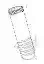
FIG. 1 shows a first embodiment of a dental implant,
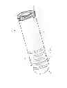
FIG. 2 shows a second embodiment of a dental implant and
FIG. 3 shows a third embodiment of a dental implant.
FIG. 1 shows a first embodiment of the implant as a dental implant 1. However, an embodiment as an implantable screw or as an implantable connection element is conceivable. The dental implant 1 comprises a base member 2 which is formed substantially cylindrically. At its outer end, i.e., at the end which when the dental implant is inserted faces towards the oral cavity, a thread 3 is disposed on the base member 2. The opposite end of the base member 2 is rounded, i.e. the inner end which is disposed in the jaw bone when the base member 2 is inserted. In FIG. 1, the inner end 4 is hemispherical. Between the inner end 4 and the thread 3, annular ridges 5 and annular recesses 6 are formed on the surface of the base member 2. The recesses 6 have the shape of grooves extending circularly around the perimeter of the base member 2. The grooves 6 are arranged adjacent to each other so that material remaining on the surface of the base member 2 between the grooves 6 forms the ridges 5. The grooves 6 and therefore also the ridges 5 are arranged near the inner end 4 and extend across approximately one third to one half of the base member 2. The remaining portion of the base member 2 from the grooves 6 to the thread 3 has a smooth surface. In this manner, the entire base member 2 has no elements which project beyond the surface of the base member 2 except in the portion in which the thread 3 is arranged. Thereby the section of the base member 2 on which no thread is arranged is formed as a sliding seat. The dental implant 1 can then be easily inserted into a cylindrical bore in the jaw bone without any stress or pressure being exerted on the surrounding tissue.
The thread 3 is preferably designed as a tapping or groove thread. The thread 3, as described above, is arranged at the outer end 7 of the implant base member 2. The thread 3 extends over a maximum of one tenth of the total length of the base member 2. The thread 3 is designed with multiple entries, and therefore comprises two or more threads turns. This enables secure and precise footing of the dental implant 1 in the jaw even with the short length of the thread 3. Due to undercuts in the implant base member 2 formed by the grooves 6, growth of the jaw bone to the dental implant 1 is facilitated. It can also be provided that the surface of the implant 1 comprises microroughnesses which again lead to improved growth of the jaw bone onto the implant. Due to the short length of the thread 3, the dental implant can be locked in the jaw bone by a short turn, preferably a turn by one half or one quarter of the perimeter of the dental implant 1.
Preferably the implant is fabricated from ceramic, in particular from zirconium oxide. The implant can be formed in one piece or in two pieces. In the one-piece design, the attachment of the superstructure, i.e. a crown or a bridge, is performed directly onto the dental implant being inserted in the jaw bone. In a two-piece design, an abutment is fastened to the base member, the superstructure is fixed to the abutment. FIG. 1 is illustrated as a two-piece design. At the outer end 7 of the base member 2, a bore 8 is provided in which an abutment can be attached.
FIG. 2 shows another embodiment of a dental implant 1′ according to the invention. This dental implant is structured as being substantially identical to the dental implant of FIG. 1. The differences are indicated below. The dental implant 1′ also comprises a base member 2′. The thread 3′ is disposed at the outer end 7′ of the base member 2′. This thread 3′ as well is formed with multiple entries. The length of the section of the base member 2′ on which the thread 3′ is disposed here as well corresponds to a maximum one tenth of the total length of the implant base member 2′.
The inner end 4′ of the base member 2′ is again rounded, preferably hemispherically. Starting from the inner end 4′ of the base member 2′, recesses are formed in the surface of the base member 2′. These recesses have the shape of circular grooves 6′ extending around the perimeter of the base member 2′ and forming closed rings. It could also be possible that the grooves are interrupted and extend diagonally on the surface of the base member 2′ as long as the pitch of a groove for a complete turn around the perimeter of the base member 2′ equals to zero. This means that the grooves 6′ are not spiral-shaped or helical and unscrewing of the implant after insertion into the jaw bone is thereby prevented. Here as well, the grooves 6′ are disposed adjacent to each other so that ridges 5′ remain on the surface of the base member 2′ between two grooves 6′. The grooves 6′ therefore form undercuts in the base member 2′ into which the jaw bone can grow. In order to further facilitate growth of the jaw bone onto the implant 1′, additional concave indentations 9′ are formed on the surface of the base member 2′. These concave indentations 9 are arranged on both the ridges 5′ as well as in the portion of the base member 2′, in which neither grooves 6′ nor any thread 3′ is disposed. Preferably, these concave indentations 9 have the shape like the surface of a golf ball (dimple). Like the dental implant 1 shown in FIG. 1, the dental implant 1′ can comprise micro-roughnesses on the surface to further facilitate growth of the jaw bone. In addition, the portion of the base member 2′, on which no thread is arranged, is formed as a sliding seat. This means that this portion comprises no elements extending beyond the actual surface of the base member 2′, so that the base member 2′ can be easily inserted into a bore in the jaw bone without applying much pressure onto the bone. A bore 8 for receiving an abutment is again fitted at the outer end 7′ of the dental implant 1. The concave indentations 9 of the dental implant 1′ in FIG. 2 are substantially circular in shape.
FIG. 3 shows yet another embodiment of a dental implant 1″. In the following, the differences to the previously described two dental implants are depicted below. The dental implant 1″ again comprises a base member 2″. A thread 3″ is disposed at the outer end 4″ of the base member 2″. The thread 3″ is formed with multiple entries and comprises four thread turns. Each of the thread turns extends across approximately one quarter of the perimeter of the dental implant 1″. The thread 3″ is again preferably a groove thread or a self-tapping thread. The implant 1″ can then be easily inserted into a bore in the jawbone and be precisely affixed by a quarter turn.
Concave indentations 9′ are formed on the surface of the base member 2″. The concave indentations 9′ start just below the thread 3″ and extend almost to the inner end 4″ of the base member 2″. The concave indentations 9′ are approximately elliptical and at the transition to the surface of the base member 2″ comprise rounded edges. This facilitates insertion of the implant 1″ into a bore in the jawbone and the growth of the jaw bone. The concave indentations 9′ are arranged on circular lines, where the circular lines extend around the perimeter of the base member 2″ and each span a plane extending perpendicular to the longitudinal axis of the implant 1″ and thereby also to the longitudinal axis of the base member 2″. The concave indentations 9′ on two adjacent circular lines are arranged offset from one another, so that a dense array of concave indentations 9′ is obtained on the surface of the base member 2″. The adjacent indentations 9′ are spaced from each other, so that a circular ridge 5″ running all around is formed between the grooves 9′ on adjacent circular lines. These ridges 5″, like in the two previous embodiments, result in the implant not being able to unscrew itself from the jaw bone, as may occur with screw implants.
The base member 2″ of the dental implant 1″' is again formed substantially cylindrical. In the lower fifth of the dental implant, the diameter of the base member 2″ decreases, so that the base member 2″ tapers out conically downwards, i.e. towards the inner end 4″. This facilitates insertion of the dental implant 1″ into a bore in the jaw bone.
The dental implant 1″ can in addition to the concave indentations 9′ also have micro-roughnesses on the surface of the base member 2″ in order to facilitate growth of the jaw bone.
Claims
1-11. (canceled)
12. Dental implant comprising:
a base member; and
a thread arranged at an outer end of said base member at which when the dental implant is inserted will face towards an oral cavity, wherein in a region of said base member having no thread, annular ridges and/or recesses are formed, wherein a length of a section of said base member on which the thread is disposed corresponds to approximately one tenth of an entire length of said base member, said thread being formed with multiple entries, and wherein a length of an individual thread turn is less than a perimeter of said base member.
13. Implant according to claim 12, wherein said annular ridges and/or recesses are closed.
14. Implant according to claim 12, wherein a section of said base member having no thread is formed as a sliding seat.
15. Implant according to claim 12, wherein said annular ridges and/or recesses are disposed on an end of said base member facing away from said thread.
16. Implant according to claim 12, wherein said annular recesses are located adjacent to each other such that they form ridges.
17. Implant according to claim 12, wherein said recesses are formed as annular grooves and/or concave indentations.
18. Implant according to claim 17, comprising said concave indentations located on annular lines.
19. Implant according to claim 18, wherein said concave indentations are arranged offset to each other on two adjacent annular lines.
20. Implant according to claim 12, wherein an inner end of said base member is rounded at an end which is to be disposed in a jaw bone when said base member is inserted.
21. Implant according to claim 12, made from ceramic, including zirconium oxide or aluminum oxide or a combination of both zirconium and aluminum oxide ceramics.
22. Implant according to claim 12, wherein a surface of said base member comprises: microroughnesses.
23. Implant according to claim 12, wherein a length of an individual thread turn is about one quarter of a perimeter of said base member.
24. Implant according to claim 13, wherein a section of said base member having no thread is formed as a sliding seat.
25. Implant according to claim 24, wherein said annular ridges and/or recesses are disposed on an end of said base member facing away from said thread.
26. Implant according to claim 25, wherein an inner end of said base member is rounded at an end which is to be disposed in a jaw bone when said base member is inserted.
27. Implant according to claim 26, made from ceramic, including zirconium oxide or aluminum oxide or a combination of both zirconium and aluminum oxide ceramics.
28. Implant according to claim 27, wherein a surface of said base member comprises: microroughnesses.
Images & Drawings included:


Sources:
- United States Patent and Trademark Office - verify current appl. status at the USPTO↗
Similar patent applications:
- » 20220087784
Dental implant, component for dental applications, implant system for dental applications, method for forming a protective layer on the surface of an implantable or implant component, implantable or implant component having a protective layer, and use of a protective layer - » 20220192794
DENTAL IMPLANT, COMPONENT FOR DENTAL APPLICATIONS, IMPLANT SYSTEM FOR DENTAL APPLICATIONS, METHOD FOR FORMING A PROTECTIVE LAYER ON THE SURFACE OF AN IMPLANTABLE OR IMPLANT COMPONENT, IMPLANTABLE OR IMPLANT COMPONENT HAVING A PROTECTIVE LAYER, AND USE OF A PROTECTIVE LAYER - » 20250134632
DENTAL IMPLANT, COMPONENT FOR DENTAL APPLICATIONS, IMPLANT SYSTEM FOR DENTAL APPLICATIONS, METHOD FOR FORMING A PROTECTIVE LAYER ON THE SURFACE OF AN IMPLANTABLE OR IMPLANT COMPONENT, IMPLANTABLE OR IMPLANT COMPONENT HAVING A PROTECTIVE LAYER, AND USE OF A PROTECTIVE LAYER - » 20120053675
MEDICAL IMPLANT, PARTICULARLY VALVE IMPLANT, FOR IMPLANTATION IN AN ANIMAL AND/OR HUMAN BODY AND METHOD, PARTICULARLY PRODUCTION METHOD, FOR PRODUCING AN IMPLANTATION APPARATUS FOR THE MEDICAL IMPLANT - » 20060105295
Implant that can be implanted in osseous tissue, method for producing said implant and corresponding implant - » 20110151400
Dental bone implant, methods for implanting the dental bone implant and methods and systems for manufacturing dental bone implants - » 20100021865
Method for manufacturing implant abutments for dental implants, and an implant abutment for a dental implant - » 20080082101
Implant, implant system, and use of an implant and implant system - » 20050026112
Bone implant method of implanting, and kit for use in making implants, particularly useful with respect to dental implants - » 20070082321
Method for manufacturing implant abutments for dental implants, and an implant abutment for a dental implant
Recent applications in this class:
- » 20250205021 2025-06-26
DENTAL IMPLANTS WITH VARYING DIAMETERS AND ALTERNATING CONCAVE/CONVEX THREAD TYPES - » 20250143846 2025-05-08
DENTAL IMPLANTS, DENTAL ASSEMBLIES, AND METHODS OF IMPLANTING AND REPAIRING DENTAL ASSEMBLIES - » 20250082442 2025-03-13
DENTAL IMPLANT - » 20240285377 2024-08-29
Implant and preparation method thereof - » 20230372067 2023-11-23
DENTAL IMPLANT FOR PRESERVING BONE AND IMPROVING OSSEOINTEGRATION - » 20230248478 2023-08-10
DENTAL IMPLANT ABUTMENT HAVING OCCLUSAL FORCE BUFFERING FUNCTION - » 20230157793 2023-05-25
DENTAL IMPLANT - » 20230144247 2023-05-11
DENTAL IMPLANT - » 20230059997 2023-02-23
DENTAL IMPLANT WITH IMPROVED STABILIZATION THREAD FORM AND CUTTING ELEMENTS - » 20220370175 2022-11-24
Dental implant able to enhance stability
Recent applications for this Assignee:
- » 20200030062 2020-01-30
IMPLANT SYSTEM - » 20190072130 2019-03-07
Active radial magnetic bearing with yoke winding - » 20190068016 2019-02-28
MULTIPOLE ROTOR WITH LOAF-SHAPED OR PIECE-OF-CAKE-LIKE PERMANENT MAGNETS - » 20180209529 2018-07-26
Compact multi-stage gear with a planetary gear and a strain wave gear adjacent to said multi-stage gear - » 20180119783 2018-05-03
Two-stage telescopic spindle drive - » 20180062464 2018-03-01
Electronically commutated electric motor with two rotor cores - » 20170151691 2017-06-01
Speciality ceramic components - » 20170149313 2017-05-25
Two-pole brush-commutated DC electric motor - » 20170110919 2017-04-20
Torque-optimized rotor and small electric motor with a rotor of this type - » 20170063190 2017-03-02
Plastic-overmolded stator system with improved heat dissipation having exposed return paths and injected crossbars