Collection of oil floating on a water surface by contact with a cold surface
US20130340970A1
2013-12-26
13/528,182
2012-06-20
✅ Patent granted
US 9,410,651 B2
2016-08-09
-
-
Robert James Popovics
2032-06-20
Abstract:
A crude oil removal device that is attached to a tethered umbilical line which feeds coolant thru the coolant coils. The refrigerated device creates an atmosphere to which crude oil will attach itself to, either floating or submerged for easy removal. The unit consists of two housings that contain the cooling coils which is sealed with rubber to maintain an air tight seal. The unit does not collect water while collecting the crude oil and can be used in virtually any weather condition.
Inventors:
- Daniel P. Lytton 1 🇺🇸 Cleveland, OH, United States
- Raymond J. Keller 1 🇺🇸 Macedonia, OH, United States
Applicant:
Interested in similar patents?
Get notified when new applications in this technology area are published.
Classification:
F16L53/70 » CPC further
Heating of pipes or pipe systems; Cooling of pipes or pipe systems Cooling of pipes or pipe systems
Y02A20/204 » CPC further
Water conservation; Efficient water supply; Efficient water use; Controlling water pollution; Waste water treatment Keeping clear the surface of open water from oil spills
F16L9/18 » CPC further
Rigid pipes Double-walled pipes; Multi-channel pipes or pipe assemblies
F24H9/00 IPC
Details
F16L9/006 » CPC further
Rigid pipes specially profiled
E02B15/10 » CPC main
Cleaning or keeping clear the surface of open water; Apparatus therefor; Devices for cleaning or keeping clear the surface of open water from oil or like floating materials by separating or removing these materials Devices for removing the material from the surface
B01D37/00 IPC
Processes of filtration
F16L53/00 » CPC main
Heating of pipes or pipe systems; Cooling of pipes or pipe systems
F16L9/00 IPC
Rigid pipes
F16L9/00 IPC
Pipes
Description
BACKGROUND
This invention relates in general to a floating, submergible, floating and/or submergible unit that will be used to collect and remove crude oil from the surface of water as well as below the surface in any weather condition.
When an oil spill occurs, it becomes a bane to the environment as well as wildlife and clean up can be extremely costly. An inordinate amount of time and resources are necessary for reclaim.
This invention will collect and remove crude oil with little to no water and without the need for dispersants in a timely and safe manner.
SUMMARY
The present invention relates to a refrigerated crude oil recovery system that is attached to a primary device and anchoring system with a tethered umbilical line that transfers coolant to and thru coils which cools an exterior and interior housing therefore creating an environment to which crude oil attaches. Submersible either in a raftable or cylindrical unit, the invention is an embodiment of one another; both are comprised of an exterior and interior housing that are sealed together with rubberlike gaskets creating a non-permeable, sealed, air-tight section containing stabilized, cooling coils that transfers coolant thru the housings.
BRIEF DESCRIPTION OF THE DRAWINGS
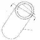
FIG. 1 (A) is a complete View of the present invention. (Cylindrical Unit) Leading to FIG. 2 (AA)
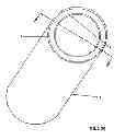
FIG. 2 (AA) is a Sectional View.
FIG. 3 is a Sectional View
FIG. 4 is a Isometric View
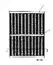
FIG. 5 (A) is a Top view of the present invention. (Raftable Unit) Leading to FIG. 6 (AA)
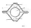
FIG. 6 (AA) is a Sectional View
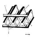
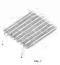
FIG. 7 is a Isometric View
FIG. 8 is a Sectional View
DETAILED DESCRIPTION
Referring now to FIGS. 1-8, the Crude Max Recovery System of the present invention is shown in both embodiments, the Cylindrical and Raftable. In FIG. 1(A) a complete view of the Cylinder shows an exterior-housing comprising of an inner-housing 1 and an outer-housing 2 which are coupled together creating an interior space between the inner housing 1 and the outer housing 2, while incorporating rubber or like product 3 to seal or cap the unit.
In FIG. 2(AA) shown is a sectional view of the Cylinder. Shown in this embodiment is the inner housing 1 and the outer housing 2 where plastic 4 or other like product is used as a stabilizing brace (referred to hereinafter “Stabilizing Braces”) attached to the inner housing 1 and outer housing 2 to secure in place cooling coils 3 to abstain from damage and or movement. The Stabilizing Braces are spaced accordingly to maintain rigidity while also permitting an optimal cooling effect. The cooling coil 3 spirals the circumference and length of the inner housing 1 and the outer housing 2 maintaining an even cooling atmosphere. Similarly, FIG. 3 shows in one position the inner housing 1 and the outer housing 2 joined together enveloping the Stabilizing Braces 4, and the cooling coil 3 when sealed. Noting the second embodiment shows the inner housing 1 and the outer housing 2 and cooling coil 3 prior to connecting and sealing the unit.
Referring now to the current invention FIG. 4 an isometric transpicuous view of the entire cylindrical unit showing the inner housing 1 and outer housing 2 creating an exterior-housing encapsulating the cooling coils 3 whilst sealing the housing ends with rubber 5 or similar product. Furthermore, again referring to FIG. 4, showing the coolingcoils 3 spaced at even intervals therefore maintaining an even and consistent cooling environment.
Referring to FIG. 5(A) A top view of the current invention shows the top housing 2 of the raftable embodiment with reinforcement bars 7 to aid in maintaining rigidity. Setting up the view of FIG. 6 (AA). In FIG. 6(AA) shown is a sectional view.
Shown in FIG. 6 (AA) is the exterior-housing 2 encapsulating collection tubes 6 and cooling coils 3. Also shown is a reinforcement bar 7 to maintain rigidity of the outer housing 2.
Continuing to FIG. 7 of the current invention is an isometric transpicuous view of the raftable embodiment, the outer housings 2 encapsulating the collection tubes 6 and the cooling coils 3 sealed together as a unit with reinforcement bars 7.
FIG. 8 of the current invention is a sectional view showing two outer housings 2, connected and sealed using rubber 5 or other like product, encapsulating the cooling coils 3 and the collection tube 6. Stabalizing Braces 5 are used to maintain the stability of the cooling coil 3 as well as the collection tube 6 whilst sealing the entire unit.
Although the principles, alternate embodiments, and operation of the present invention have been described in detail herein, the crude max recovery system is not to be construed as being limited to the particular illustrative forms disclosed. It will thus become apparent to those skilled in the art that various modifications of the embodiments herein can be made without departing from the spirit or scope of the invention by the following claims.
Claims
1. A Crude Oil Collection Device which will collect crude oil from a body of water on or below the surface comprising;
An inner and outer housing using either a ferrous or non ferrous metal coupled together and sealed with a rubber like substance creating a non permeable water tight atmosphere that holds and stabilizes the coolant coils encapsulated within the exterior and interior housing collectively allowing the transference of coolant to the housings maintaining a temperature that is considerably colder then the body of water in which it floats and or submerges in and creates a temperature difference conducive to attracting crude oil to attach to the exterior and interior housing.
2. Citing the above claim the crude oil collection device wherein a tethered line is adapted for attachment and affixed with a cable to the housing also at the same time feeding and returning coolant and controlling the position of the unit.