Method for determining when a Li-ion cell comprising a negative electrode made of an alloy is fully charged, associated cell and battery
US20140004398A1
2014-01-02
14/004,956
2012-03-16
✅ Patent granted
US 9,246,198 B2
2016-01-26
WO; PCT/EP2012/054632; 20120316
WO; WO2012/126817; 20120927
Gregg Cantelmo
Pearne & Gordon LLP
2032-06-11
Abstract:
The invention relates to a method for determining the end-of-charging condition of a lithium-ion accumulator with a negative electrode formed with at least one alloy, according to which a surface pressure with a determined force from the external portion of the accumulator (A) against an element (2, 2′, 3) is detected, the surface pressure being generated by the thickness increase due to ion insertion at the negative electrode and thereby defining the end-of-charging condition.
Assignee:
- Commissariat A L'Energie Atomique Et Aux Energies Alternatives 4,902 🇫🇷 Paris, France
Applicant:
Interested in similar patents?
Get notified when new applications in this technology area are published.
Classification:
H01M10/48 » CPC main
Secondary cells; Manufacture thereof; Methods or arrangements for servicing or maintenance of secondary cells or secondary half-cells Accumulators combined with arrangements for measuring, testing or indicating the condition of cells, e.g. the level or density of the electrolyte
H01M4/485 IPC
Electrodes; Electrodes composed of, or comprising, active material; Selection of substances as active materials, active masses, active liquids of inorganic oxides or hydroxides of mixed oxides or hydroxides for inserting or intercalating light metals, e.g. LiTiO or LiTiOxFy
H01M10/482 » CPC further
Secondary cells; Manufacture thereof; Methods or arrangements for servicing or maintenance of secondary cells or secondary half-cells; Accumulators combined with arrangements for measuring, testing or indicating the condition of cells, e.g. the level or density of the electrolyte for several batteries or cells simultaneously or sequentially
H01M10/058 » CPC further
Secondary cells; Manufacture thereof; Accumulators with non-aqueous electrolyte Construction or manufacture
H01M10/0525 » CPC further
Secondary cells; Manufacture thereof; Accumulators with non-aqueous electrolyte; Li-accumulators Rocking-chair batteries, i.e. batteries with lithium insertion or intercalation in both electrodes; Lithium-ion batteries
H01M4/134 » CPC further
Electrodes; Electrodes composed of, or comprising, active material; Electrodes for accumulators with non-aqueous electrolyte, e.g. for lithium-accumulators; Processes of manufacture thereof Electrodes based on metals, Si or alloys
H01M4/505 IPC
Electrodes; Electrodes composed of, or comprising, active material; Selection of substances as active materials, active masses, active liquids of inorganic oxides or hydroxides of manganese of mixed oxides or hydroxides containing manganese for inserting or intercalating light metals, e.g. LiMnO or LiMnOxFy
H01M4/52 IPC
Electrodes; Electrodes composed of, or comprising, active material; Selection of substances as active materials, active masses, active liquids of inorganic oxides or hydroxides of nickel, cobalt or iron
H01M4/525 IPC
Electrodes; Electrodes composed of, or comprising, active material; Selection of substances as active materials, active masses, active liquids of inorganic oxides or hydroxides of nickel, cobalt or iron of mixed oxides or hydroxides containing iron, cobalt or nickel for inserting or intercalating light metals, e.g. LiNiO, LiCoO or LiCoOxFy
H01M4/58 IPC
Electrodes; Electrodes composed of, or comprising, active material; Selection of substances as active materials, active masses, active liquids of inorganic compounds other than oxides or hydroxides, e.g. sulfides, selenides, tellurides, halogenides or LiCoF; of polyanionic structures, e.g. phosphates, silicates or borates
H01M4/587 IPC
Electrodes; Electrodes composed of, or comprising, active material; Selection of substances as active materials, active masses, active liquids of inorganic compounds other than oxides or hydroxides, e.g. sulfides, selenides, tellurides, halogenides or LiCoF; of polyanionic structures, e.g. phosphates, silicates or borates; Carbonaceous material, e.g. graphite-intercalation compounds or CFx for inserting or intercalating light metals
H01M4/131 » CPC further
Electrodes; Electrodes composed of, or comprising, active material; Electrodes for accumulators with non-aqueous electrolyte, e.g. for lithium-accumulators; Processes of manufacture thereof Electrodes based on mixed oxides or hydroxides, or on mixtures of oxides or hydroxides, e.g. LiCoOx
Description
TECHNICAL FIELD
The invention relates to a method for determining the end-of-charging condition of a lithium-ion accumulator with a negative electrode formed with at least one alloy.
The invention is directed to providing a simple and reliable indicator for the end-of-charging condition of this type of lithium-ion (abbreviated as Li-ion) accumulator.
The invention also relates to a device comprising a lithium-ion accumulator of this type as well as to an assembly of several accumulators of this type currently called a battery pack, for applying the method.
PRIOR ART
A negative electrode of a lithium-ion accumulator may be formed with a single alloy, or with a mixture of alloys, or with a mixture of alloy(s) and of other material(s) for lithium insertion (graphite, in the synthetic or natural form, Li4Ti5O12, TiO2 . . . ). This negative electrode may also contain electron conducting additives as well as polymeric additives which give it suitable mechanical properties and electrochemical performances for the lithium-ion battery application or for its application method.
During its electrochemical alloying with the lithium ion Li+, the negative electrode formed with at least one alloy is subject to a significant increase in its crystallographic lattice parameter. This significant increase in the crystallographic lattice parameter of the alloy cannot be absorbed by the intrinsic porosity of the negative electrode. In other words, during successive charging cycles, the negative electrode is also subject to increases in dimensions, mainly in its thickness. Gradually, given that the whole of the constituents of a Li-ion battery, i.e. separator, electrode, collectors, and packaging, have low elasticity, the significant increase in the crystallographic lattice parameter of the alloy induces stress on the packaging or deformation of the latter depending on its stiffness.
The expansion of the alloy, during charging of a Li-ion accumulator with a negative electrode formed with at least one alloy, may be harmful to the actual accumulator, to the packaging which contains it, to the assembly of several Li-ion accumulators (Li-ion battery pack) or to the system integrating the Li-ion battery or the Li-ion battery pack if the deformation of the packaging, the pressure inside the latter or the pressure exerted by the latter on any other part is not under control.
Usually, the conventional method for obtaining an indicator of the end-of-charging condition for a lithium-ion accumulator is to track the charging condition from its voltage and/or the current. More or less complex methods exist and notably take into account the ohmic resistance and/or its temperature. Mention may be made here of patent application US 2010/0121591. These methods do not practically control the pressure or the exerted deformation mentioned above.
Continuous measurement of the physical displacement of the polymeric flexible packaging of the Li-ion accumulator or the pressure increase of the latter against an element, is known from patent U.S. Pat. No. 5,438,249, this change in the displacement or pressure increase being generated by the increase in thickness due to ion insertion at the negative electrode. Two embodiments are provided:
-
- the one of FIG. 5 according to which a polymeric stack of Li-ion accumulators 40 is laid out between two stiff plates 41, 43 held together by a spring and between which a linear displacement gauge 45 is connected allowing continuous detection of the displacement,
- the one of FIG. 6 according to which a stack of the same type 50 and a flexible pocket 51 permanently bearing against the stack 50 are laid out in a stiff housing 53; the flexible pocket 50 is filled with a liquid and is extended with a tube 55 which extends on the outside of the stiff housing 53. The pressure increase generates a rise of the liquid level in the tube 55, which allows continuous detection.
The detectors used 45, 50, 55 necessarily have to be very accurate since the thickness increases are very small, of the order of a few micrometers. Further, these detectors are not simple to apply. Finally, the detection of the thickness increase is only global, i.e. it can only be accomplished for the assembly of the stack 40 or 50 and not individually for each accumulator 30 forming said stack.
The object of the invention is then to propose a solution which is simple to apply and reliable, allowing determination of the end-of-charging condition of an Li-ion accumulator with a negative electrode formed with at least one alloy, in order to avoid any deterioration of the accumulator, of its packaging, of an Li-ion battery pack with several accumulators of this type, or of a complete Li-ion system notably comprising an Li-ion battery pack and integrated electronic components.
DISCUSSION OF THE INVENTION
To do this, the object of the invention is a method for determining the end-of-charging condition of a lithium-ion accumulator with a negative electrode formed with at least one alloy, according to which a surface pressure with a determined force of the external portion of the accumulator against an element is detected, the surface pressure being generated by the thickness increase due to ion insertion at the negative electrode and thus defining the end-of-charging condition.
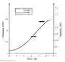
The inventors first of all showed that the thickness of a negative electrode formed with at least one alloy of a lithium-ion accumulator monotonously changed over time like the capacity of the accumulator over time during charging with a constant current completed by a step with an imposed potential, as this is apparent from FIG. 1. They drew the conclusion therefrom that the charging of such an accumulator may be stopped as soon as the volume expansion, mainly along the thickness of the negative electrode alloy had reached a threshold. Thus, they had the idea of detecting this threshold of thickness increase of the negative electrode by the volume expansion of the alloy(s) by producing surface pressure with another element operating as a mechanical abutment. Thus, according to the invention by proposing a mechanical abutment for the accumulator, the thickness of which increases during the charging, an end-of-charging condition is defined which is simple to apply and reliable. Further, the method according to the invention may be used as an addition to already existing methods for tracking the charging condition, which continuously measure the latter. Here, by means of the invention, it is ensured that no damage is induced on an accumulator or its environment during a charging step.
Advantageously, a determined force of the surface pressure, at least equal to 50 N, is detected.
Still advantageously, the thickness increase generating the surface pressure is at least equal to 0.1 mm.
The invention also relates to a device for applying the method described earlier, comprising:
-
- at least one lithium-ion accumulator, comprising at least one electrochemical cell consisting of at least one negative electrode with lithium insertion, formed with at least one alloy and a cathode on either side of an electrolyte, and a packaging laid out for containing the electrochemical cell(s) with a seal,
- a stiff casing under the pressure exerted by at least one accumulator, generated by the thickness increase due to the ion insertion at the negative electrode,
- at least one means for mechanically attaching the accumulator, during the thickness increase due to the ion insertion at the negative electrode, allowing the accumulator to be held in place in the stiff casing,
- at least one force sensor attached to the external portion of the packaging or on one of the inner faces of the stiff casing, said force sensor being capable of assuming two conditions, one being a so-called discharge condition, in which it is at a distance or bearing on a surface under a respectively determined force of the stiff casing or of the external portion of the packaging, and the other condition, a so-called end-of-charging condition, in which it is bearing upon a surface respectively against the stiff casing or against the external portion of the packaging with the determined force.
It is specified here that during the charging of the accumulator(s), the battery charger is connected to the electric network and therefore the low electric consumption of the force sensor has only very little influence on the charge, strictly speaking, of the accumulator(s) (battery).
It is also specified that:
-
- for an accumulator with a geometry of the prismatic type, the mechanical holding means is(are) laid out in a plane normal to the main deformation of the accumulator,
- for an accumulator with a geometry of the cylindrical type, the mechanical holding means is(are) laid out in a plane normal to the axis of revolution of the cylinder.
When it is desired to make a so-called battery pack assembly, the device may comprise:
-
- a stack of a plurality of separate lithium-ion accumulators between lateral mechanical supports for holding the accumulator(s) in place within the stack, the accumulator of the bottom being held in place by the mechanical attachment means and the accumulator of the top being separate from the stiff casing by at least one empty space or directly in contact on a force sensor,
- a plurality of force sensors, including at least one force sensor attached to the external portion of the stack of the accumulator of the top of the stack or inside the stiff casing, and at least one force sensor attached to the external portion of the packaging of each accumulator within the stack, each force sensor within the stack being also able to be in a discharge condition, in which it is at a distance or bearing upon a surface under a determined force from the external portion of another accumulator and an end-of-charging condition, in which it is bearing upon a surface against the external portion of the packaging of another accumulator with the determined force.
The invention also relates to a device for applying the method described earlier, comprising:
-
- at least one lithium-ion accumulator, comprising at least one electrochemical cell consisting of at least one negative electrode with lithium insertion, formed with at least one alloy and a positive electrode separated by a separator impregnated with electrolyte, and a packaging laid out for containing the electrochemical cell(s) with a seal,
- a stiff casing under the pressure exerted by at least one accumulator, generated by the thickness increase due to ion insertion at the negative electrode,
- at least one means for mechanically attaching the accumulator during the thickness increase due to ion insertion at the negative electrode, allowing the accumulator to be held in place in the stiff casing,
- a contactor, the mobile portion of which is attached to the external portion of the packaging of the accumulator and the fixed portion is attached inside the stiff casing, the mobile portion of the contactor being able to move between a position, a so-called discharge position, in which it is at a distance from the fixed portion of the contactor, a so-called end-of-charging position, in which it bears upon a surface against the fixed portion of the contactor with a determined force.
When it is desired to produce a battery pack assembly, the device may comprise:
-
- a stack of a plurality of lithium-ion accumulators separated from each other by lateral mechanical supports for holding the accumulator(s) in place within the stack, the accumulator of the bottom being held in place by the mechanical attachment means and the accumulator of the top being separated from the stiff casing (3) by at least one empty space,
- a plurality of contactors, including at least one contactor with its mobile portion attached to the external portion of the packaging of the accumulator of the top and/or of the bottom of the stack and with its fixed portion attached inside the stiff casing, and at least one contactor with a mobile portion attached to the external portion of the packaging of each accumulator within the stack, each mobile contactor portion within the stack being also able to move between a discharge position, in which it is at a distance from another mobile contactor position attached to the external portion of another accumulator, and an end-of-charging position, in which it bears upon a surface against the other mobile contactor portion attached to the external portion of the packaging of another accumulator with the determined force.
It is specified here that in a battery pack according to the invention, the end of charging is reached as soon as one of the contactors closes or one of the force sensors has reached its pressure force determined beforehand, preferably of at least 50 N.
It is also specified that in a battery pack according to the invention, suitable means are provided for achieving active balancing among all the accumulators of the battery pack so that they all remain in the same charging state during a charging step.
Finally it is specified that when all the accumulators of the stack individually have on either side an empty space, in other words when they are somewhat floating, provision is made for all the lateral mechanical holding means, such as wedges, substantially having the same height among each other.
Thus it is possible by means simple to apply and for which reliability is proven (contactor or force sensor), to detect a threshold deformation value of a negative electrode formed with at least one alloy which should not be exceeded in order to avoid any risk of damage.
The mechanical attachment means between the accumulator and the stiff casing may advantageously be an adhesive. Thus, the mechanical attachment means of the accumulator, the closest to the bottom of the stiff casing may be an adhesive for attaching said accumulator to the latter.
Each negative electrode may be formed with a single alloy (Si, Sn, Al, Sb . . . ), with a mixture of alloy(s) or a mixture of alloy(s) and of other lithium insertion material(s), such as graphite, Li4Ti5O12, TiO2.
Each positive electrode may be formed with a lamellar oxide, such as LiMO2, with M═Co, Ni, Mn, Al, Mg or a mixture thereof, or with a spinel oxide of general formula LiM2O4, such as manganese spinel LiMn2O4 or high voltage spinel LiMn1.5Ni0.5O4, or in material(s) based on phosphate, such as LiMPO4 with M═Co, Ni, Fe, Mn, Mg, B or a mixture thereof, or with over-stoichiometric lamellar oxides of formula Li( 1+x)MOy with M═Ni, Co, Mn, or a mixture thereof wherein 0.5<x<2 et 2<y<3.
Each electrolyte ensuring ion conduction between electrodes may be liquid, such as based on carbonates or in the form of a gelled polymer conducting lithium ions or an ionic liquid. Any other stable compound at the contemplated potentials (0 to 5 Volts vs. Li+/Li) and allowing dissolution of a lithium salt, such as usually LiPF6, may also be contemplated.
Each separator ensuring the electric insulation between electrodes consists of a membrane which is porous to the electrolyte which impregnates it, said membrane being based on polymer. Any other electrically insulating and ion conducting constituent for lithium ions may also be contemplated.
SHORT DESCRIPTION OF THE DRAWINGS
Other features and advantages will become better apparent upon reading the detailed description made hereafter as an illustration and not as a limitation with reference to the following figures wherein:
FIG. 1 shows the time-dependent change in the capacity and in the thickness of a lithium-ion accumulator with a negative electrode formed with at least one alloy versus time during charging with a constant current completed with a constant potential step,
FIG. 2 is a schematic sectional view of a device according to a first embodiment of the invention with a single lithium-ion accumulator with a negative electrode formed with at least one alloy,
FIG. 3 is a schematic sectional view of a device according to a first embodiment of the invention with a stack of three lithium-ion accumulators with a negative electrode formed with at least one alloy,
FIG. 4 is a schematic sectional view of a device according to a second embodiment of the invention with a single lithium-ion accumulator with a negative electrode formed with at least one alloy,
FIG. 5 is a schematic sectional view of a device according to a second embodiment of the invention with a stack of three lithium-ion accumulators with a negative electrode formed with at least one alloy,
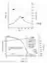
FIG. 6 shows the time-dependent change in the deformation depending on the thickness of a lithium-ion accumulator with a negative electrode formed with at least one alloy versus a charging/discharging cycle over time,
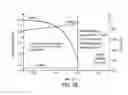
FIG. 7A shows the time-dependent change in the stress, in the potential and in the current of a lithium-ion accumulator with a negative electrode formed with at least one alloy, the stress being measured by a force sensor between the accumulator and a nearby fixed element and the charging being stopped as according to the state of the art by detecting a current threshold,
FIG. 7B shows the time-dependent change in the stress, the potential and in the current of a lithium-ion accumulator with a negative electrode formed with at least one alloy, the stress being measured by a force sensor between the accumulator and a nearby fixed element and the charging being stopped as according to the invention by detecting a force threshold with the senor.
DETAILED DISCUSSION OF PARTICULAR EMBODIMENTS
The description of FIG. 1 has already been made in the preamble and will therefore not be further described here.
An exemplary lithium-ion accumulator with a negative electrode formed with at least one alloy according to the invention is now described.
The negative electrode is formed with:
-
- silicon in the form of nanometric or micrometric particles in a proportion comprised between 10 and 98% of the mass, forming an alloy with lithium,
- electron conductors in a proportion comprised between 1 and 20% of the mass,
- binders in a proportion comprised between 1 and 30% of the mass. This porous negative electrode, the porosity of which is comprised between 15 and 50% of the volume, is deposited on a current collector in copper.
The positive electrode is formed with:
-
- a lithium oxide of the LiNixMnyCozO2 type in a proportion comprised between 80 and 98% of the mass,
- electron conductors in a proportion comprised between 1 and 10% of the mass,
- binders in a proportion comprised between 1 and 10% of the mass. This porous positive electrode, the porosity of which is comprised between 15 and 50% of the volume, is deposited on a current collector in aluminum.
Both of these electrodes (negative electrode and positive electrode) are wound on a prismatic mandrel separated by a separator based on porous polyethylene, with a porosity comprised between 20 and 60% of the volume and with a small thickness typically from 5 to 50 μm.
The wound thickness of the electrochemical core, including both electrodes and the separator is 4.5 mm, including:
-
- about 3 mm of positive electrode and of aluminum collector,
- about 1 mm of negative electrode and of copper collector,
- about 0.5 mm of separator.
The electrochemical core is packaged with a flexible bag, forming a flexible packaging, which is heat-sealed at the moment of the activation with an electrolyte which is a mixture of carbonate containing a lithium salt, such as for example a mixture of ethylene carbonate and of dimethyl carbonate in a proportion of 1:1 with LiPF6 at a concentration of 1 mol/L.
Thus, a Li-ion accumulator with a negative electrode formed with at least one alloy according to the invention has a thickness of about 4.7 mm, when it is activated.
During charging/discharging cycles, the Li-ion accumulator according to the invention is subject to changes in its thickness because of the low stiffness of the packaging. These thickness changes in the Li-ion accumulator according to the invention were measured from a strain gauge attached on the external portion of the flexible packaging: the measurements are shown in FIG. 6. Thus it may be seen that the thickness may be increased up to about 5.7 mm on the first cycle, which represents an increase by about 21% relatively to the thickness of the activated accumulator.
It is specified that in this FIG. 6, the cycling rate conditions are indicated as equal to C/20, which corresponds to 20 hours required for carrying out charging or discharging.
Thus, in order to determine the end-of-charging condition, it is possible to integrate a contactor or a force sensor into a stiff casing of a single accumulator or of a stack of accumulators in order to avoid that too significant stress appears on the stiff casing.
FIGS. 2 and 4 show the integration respectively of a contactor 2 or of a force sensor 2′ into a device 1,1′ according to the invention comprising a single lithium-ion accumulator A as defined in the example above. More exactly, the accumulator A is held in place in the stiff casing 3 by adhesive bonding on its face facing the stiff casing and where the deformation, due to the ion insertion at the negative electrode, is a main deformation. The mobile portion 20 of the contactor 2 is attached on the external portion of the flexible packaging of the accumulator A. The fixed portion 21 of the contactor 2 is attached on the internal wall of the stiff casing facing the mobile portion 20. The force sensor 2′ is, as for it, attached on the internal wall of the stiff casing 3.
FIGS. 3 and 5 show the integration of respectively a contactor 2 or a force sensor 2′ into a device 10,10′ according to the invention comprising a stack of three lithium-ion accumulators A1, A2, A3 as defined in the example above. The layout of the accumulators is achieved like for FIGS. 2 and 4, except that lateral mechanical supports 4, laid out in the plane normal to the main deformation, hold in place the accumulator A2 inserted in the stack. The attachment of the contactors 2 and force sensors 2′ is also achieved like for FIGS. 2 and 4, except that two mobile portions 20 of contactors or two force sensors 2′ are attached on either side of the external portion of the packaging of the accumulator A2 of the center of the stack.
Thus, a force threshold of the contactors 2 or force sensors 2′ is defined with respect to considerations based on the acceptable deformation of the stiff casing 3 for use, which here is 200 N. The charging voltage threshold, which is based on electrochemical considerations, is defined to be 4.2 V for charging with a current of less than 10 mA. Both of these end-of-charging indicators are actually complementary as shown in FIGS. 7A and 7B, wherein charging is stopped respectively by the indicator of the end of potential charging like according to the state of the art and/or by the stress end-of-charging indicator 2,2′ according to the invention.
In these FIGS. 7A and 7B, the terminology C/n corresponds to the number n of hours required for carrying out a cycle C. The abbreviation CV means that the voltage is set to a specific value while allowing the current to decrease for finishing the charging.
It is specified that within the scope of the invention, the adjustment of a contactor or a force sensor is definitive and does not vary according to the number of charging/discharging cycles of the accumulator(s). An end-of-charging condition is thereby defined as soon as the maximum deformation is reached.
Claims
1-11. (canceled)
12. A method for determining the end-of-charging condition of a lithium-ion accumulator with a negative electrode formed with at least one alloy, according to which surface pressures with determined forces between the external surfaces of the facing accumulators, said surface pressures being generated by the thickness increase of at least one accumulator, due to ion insertion at its negative electrode and thereby defining the end-of-charging condition.
13. The method according to claim 12, according to which a determined force of a surface pressure at least equal to 50 N is detected.
14. The method according to claim 12, according to which the thickness increase generating the surface pressure is at least equal to 0.1 mm.
15. A device for applying a method according to claim 12, comprising:
a stack of a plurality of lithium-ion accumulators, each accumulator comprising at least one electrochemical cell consisting of at least one negative electrode with lithium insertion, formed with at least one alloy, a positive electrode and a separator impregnated with electrolyte and a packaging laid out for containing each electrochemical cell with a seal;
a stiff casing under the pressure exerted by said at least one accumulator, generated by the increase of its thickness due to ion insertion at its negative electrode;
the accumulator in the accumulator stack being held in place in the stiff casing with lateral mechanical supports, laid out in a plane normal to the main deformation;
at least two mobile portions of contactors or two force sensors attached on either side of the external portion of the packaging of the accumulator, each sensor within the stack being also capable of being in a discharge condition, in which it is at a distance or bearing upon a surface under a determined force from the external portion of another accumulator and an end-of-charging condition, in which it bears upon a surface against the external portion of the packaging of another accumulator with the determined force.
16. The device according to claim 15, comprising at least one sensor attached to the external portion of the packaging of the accumulator of the top or to the inside of the stiff casing.
17. The device according to claim 15, comprising:
the accumulator of the bottom held in place by mechanical attachment means and the accumulator of the top separated from the stiff casing by at least one empty space;
at least one contactor with its mobile portion attached to the external portion of the packaging of the accumulator of the top of the stack and its fixed portion attached to the inside of the stiff casing.
18. The device according to claim 17, according to which the means for mechanically attaching the accumulator the closest to the bottom of the stiff casing is an adhesive.
19. The device according to claim 15, wherein each negative electrode is formed with a single alloy or with a mixture of alloy(s) and of other lithium insertion material(s) such as graphite Li4Ti5O12, TiO2.
20. The device according to claim 15, wherein each positive electrode is formed with a lamellar oxide, such as LiMO2, with M═Co, Ni, Mn, Al, Mg or a mixture thereof, or a spinel oxide of general formula LiM2O4, such as manganese spinel LiMn2O4 or high voltage spinel LiMn1.5Ni0.5O4, or in material(s) based on phosphate, such as LiMPO4 with M═Co, Ni, Fe, Mn, Mg, B or a mixture thereof, or over-stoichiometric lamellar oxides of formula Li(1+x)MOy with M═Ni, Co, Mn, or a mixture thereof wherein 0.5<x<2 and 2<y<3.
21. The device according to claim 15, wherein each electrolyte ensuring iron conduction between the electrodes is in liquid, for example based on carbonates or in the form of a gelled polymer conducting lithium ions or of a ionic liquid.
22. The device according to claim 15, wherein each separator ensuring electric insulation between electrodes consists of a membrane porous to the electrolyte which impregnates it, said membrane being based on polymer.
Images & Drawings included:


Sources:
- United States Patent and Trademark Office - verify current appl. status at the USPTO↗
Recent applications in this class:
- » 20250293326 2025-09-18
METHOD AND SYSTEM FOR DETECTING BATTERY DEFECT IN FORMATION PROCESS - » 20250266518 2025-08-21
CELL CONFIGURED FOR PENETRATION TEST - » 20250239669 2025-07-24
SYSTEMS AND METHODS FOR GENERATING ROLL MAP AND MANUFACTURING BATTERY USING ROLL MAP - » 20250238111 2025-07-24
SYSTEMS AND METHODS FOR GENERATING ROLL MAP AND MANUFACTURING BATTERY USING ROLL MAP - » 20250233218 2025-07-17
Pouch-Shaped Battery Cell and Battery Module Including the Same - » 20250226466 2025-07-10
PRESSURE-MONITORING FOR ELECTROCHEMICAL CELLS AND RELATED DEVICES AND SYSTEMS - » 20250210739 2025-06-26
BATTERY HOUSING STRUCTURE - » 20250201951 2025-06-19
POWER STORAGE APPARATUS - » 20250192255 2025-06-12
BATTERY SYSTEM - » 20250192254 2025-06-12
BATTERY MANAGEMENT SYSTEM, BATTERY PACK, ELECTRIC VEHICLE, AND BATTERY MANAGEMENT METHOD
Recent applications for this Assignee:
- » 20250294920 2025-09-18
METHOD FOR FORMING A LAYER WITH THE BASIS OF A DIELECTRIC MATERIAL ON A LAYER WITH THE BASIS OF AN ETCHED III-V MATERIAL - » 20250294269 2025-09-18
DEPTH PIXEL WITH SWITCHABLE INTEGRATION CAPABILITY - » 20250289195 2025-09-18
PROCESS FOR PRODUCING, AT THE END OF A STRUCTURE, A MICRO-OR NANO-COMPONENT MADE OF VITREOUS MATERIAL PRODUCED BY MULTI-PHOTON PHOTOPOLYMERIZATION - » 20250287705 2025-09-11
LIGHTWEIGHT, IMPACT-RESISTANT PHOTOVOLTAIC MODULE - » 20250285310 2025-09-11
METHOD FOR MAPPING A SPATIAL DISTRIBUTION OF A CHARACTERISTIC - » 20250279402 2025-09-04
OPTOELECTRONIC DEVICE INCLUDING A LIGHT-EMITTING DIODE STACKED ON A PHOTODETECTOR - » 20250270669 2025-08-28
METHOD FOR IRRIGATING A POROUS SUBSTRATE USING A FOAM, AND THE USES THEREOF - » 20250270148 2025-08-28
METHOD AND SYSTEM FOR TREATING ANIMAL PRODUCTS - » 20250266322 2025-08-21
SUBSTRATE COMPRISING VIAS AND ASSOCIATED MANUFACTURING METHODS - » 20250263865 2025-08-21
PROCESS FOR PRODUCING A CRYSTALLINE LAYER