Methods for balancing a disk drive
US20140063654A1
2014-03-06
13/596,452
2012-08-28
✅ Patent granted
US 8,683,677 B2
2014-04-01
-
-
Paul D Kim
Braden Katterheinrich
2032-08-28
Abstract:
In certain embodiments, a hard disk drive includes at least one disk secured to a motor hub with a disk clamp. The disk clamp is positioned radially off-center with respect to the hub to balance a static drive imbalance.
In certain embodiments, a method includes radially offsetting a disk clamp to offset a static drive balance.
Inventors:
- Darius Alisantoso 4 🇸🇬 Singapore, Singapore
- Terence Cheekwong Cheng 2 🇸🇬 Singapore, Singapore
- S Selvaruban 3 🇸🇬 Singapore, Singapore
- Sok Li Goh 4 🇸🇬 Singapore, Singapore
Assignee:
- SEAGATE TECHNOLOGY LLC 3,207 🇺🇸 Cupertino, CA, United States
- Seagate Technology 24 🇺🇸 Cupertino, CA, United States
Applicant:
Interested in similar patents?
Get notified when new applications in this technology area are published.
Classification:
G11B19/2027 » CPC further
Driving, starting, stopping record carriers not specifically of filamentary or web form, or of supports therefor; Control thereof; Control of operating function ; Driving both disc and head; Driving; Starting; Stopping; Control thereof; Turntables, hubs and motors for disk drives; Mounting of motors in the drive Turntables or rotors incorporating balancing means; Means for detecting imbalance
G11B7/094 » CPC further
Recording or reproducing by optical means, e.g. recording using a thermal beam of optical radiation , reproducing using an optical beam at lower power ; Record carriers therefor; Disposition or mounting of heads or light sources relatively to record carriers with provision for moving the light beam or focus plane for the purpose of maintaining alignment of the light beam relative to the record carrier during transducing operation, e.g. to compensate for surface irregularities of the latter or for track following Methods and circuits for servo offset compensation
Y10T29/49004 » CPC further
Metal working; Method of mechanical manufacture; Electrical device making including measuring or testing of device or component part
Y10T29/49025 » CPC further
Metal working; Method of mechanical manufacture; Electrical device making; Electromagnet, transformer or inductor; Magnetic recording reproducing transducer [e.g., tape head, core, etc.] Making disc drive
Y10T29/49032 » CPC further
Metal working; Method of mechanical manufacture; Electrical device making; Electromagnet, transformer or inductor; Magnetic recording reproducing transducer [e.g., tape head, core, etc.] Fabricating head structure or component thereof
Y10T29/53174 » CPC further
Metal working; Means to assemble or disassemble; Means to assemble electrical device Means to fasten electrical component to wiring board, base, or substrate
G11B17/02 IPC
Guiding record carriers not specifically of filamentary or web form, or of supports therefor Details
G11B7/0945 » CPC further
Recording or reproducing by optical means, e.g. recording using a thermal beam of optical radiation , reproducing using an optical beam at lower power ; Record carriers therefor; Disposition or mounting of heads or light sources relatively to record carriers with provision for moving the light beam or focus plane for the purpose of maintaining alignment of the light beam relative to the record carrier during transducing operation, e.g. to compensate for surface irregularities of the latter or for track following Methods for initialising servos, start-up sequences
G01R17/08 » CPC further
Measuring arrangements involving comparison with a reference value, e.g. bridge; Arrangements in which the value to be measured is automatically compared with a reference value; Automatic balancing arrangements in which a force or torque representing the measured value is balanced by a force or torque representing the reference value
G01R3/00 » CPC main
Apparatus or processes specially adapted for the manufacture of measuring instruments
G01R17/02 » CPC further
Measuring arrangements involving comparison with a reference value, e.g. bridge Arrangements in which the value to be measured is automatically compared with a reference value
G11B5/127 IPC
Recording by magnetisation or demagnetisation of a record carrier; Reproducing by magnetic means; Record carriers therefor Structure or manufacture of heads, e.g. inductive
H04R31/00 IPC
Apparatus or processes specially adapted for the manufacture of transducers or diaphragms therefor
G11B7/09 IPC
Recording or reproducing by optical means, e.g. recording using a thermal beam of optical radiation , reproducing using an optical beam at lower power ; Record carriers therefor; Disposition or mounting of heads or light sources relatively to record carriers with provision for moving the light beam or focus plane for the purpose of maintaining alignment of the light beam relative to the record carrier during transducing operation, e.g. to compensate for surface irregularities of the latter or for track following
Description
SUMMARY
Certain embodiments of the present disclosure are generally directed to methods and devices for balancing a disk drive.
In certain embodiments, a hard disk drive includes at least one disk secured to a motor hub with a disk clamp. The disk clamp is positioned radially off-center with respect to the hub to balance a static drive imbalance.
In certain embodiments, a method includes radially offsetting a disk clamp to offset a static drive balance.
BRIEF DESCRIPTION OF THE DRAWINGS
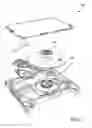
FIG. 1 provides an exploded, perspective view of a hard disk drive, in accordance with certain embodiments of the present disclosure.
FIG. 2 provides a top view of a disk and motor, in accordance with certain embodiments of the present disclosure.
FIG. 3 provides a block diagram, in accordance with certain embodiments of the present disclosure.
FIG. 4 provides a block diagram, in accordance with certain embodiments of the present disclosure.
DETAILED DESCRIPTION
The present disclosure relates to devices, systems, and methods for offsetting or balancing a static drive imbalance. A hard disk drive's static imbalance can be caused by several imbalances. One such imbalance is a disk imbalance where a disk is not concentric with a motor hub, and as a result, causes an imbalance. Another imbalance that contributes to a drive's overall static imbalance is a clamp imbalance—resulting when a disk clamp is not concentric with a motor hub. Motor imbalances also can contribute to a drive's static imbalance. A motor imbalance is generated when a motor's center of rotation does not match a motor's center of gravity.
The aforementioned imbalances contribute to a drive's static imbalance and can affect drive performance. For example, imbalances can generate eccentric loads, which can cause misalignment errors when reading data from and writing data to a disk in a hard disk drive. Imbalances may also generate vibration and noise. Static imbalance can vary from drive to drive and can be unpredictable. Certain embodiments of the present disclosure are accordingly directed to systems, devices, and methods for offsetting a hard disk drive's static imbalance.
FIG. 1 provides an exploded perspective view of a hard disk drive 100 having a disk 102, motor 104, and disk clamp 106. Only one disk is shown, but hard drives can employ a number of disks. The disk 102 is secured to the motor 104 by the disk clamp 106 so that, during operation, the disk 102 rotates with the motor 104. The disk clamp 106 can be secured to the motor 104 by fasteners such as screws. For example, the motor 104 and disk clamp 106 in FIG. 1 are each shown as having three areas for receiving fasteners.
FIG. 2 shows a top view of a disk 200 and a motor hub 202. As shown, the disk 200 is biased against the motor hub 202. Specifically, a portion of an inner diameter 204 of the disk 200 sits against the motor hub 202 causing the disk 200 to be eccentric to the motor hub 202. This eccentricity contributes to a static imbalance of a disk drive.
In FIG. 2, examples of imbalances are represented by arrows (F1 and F2) where a length of each arrow's tail is a magnitude of an imbalance and each arrow's direction is a direction of an imbalance. An overall static drive imbalance is represented by a resultant arrow (FR). These arrows are just examples and it should be recognized that magnitudes and directions of static imbalances can vary from drive to drive. Typically, the magnitude and direction of the magnitude is unknown until a disk or disks are secured to a motor hub. The resultant (FR) represents a vector summation of various drive imbalances. For example, if a drive has multiple disks, the resultant would represent a vector summation that includes imbalances resulting from each disk's eccentricity. Below is a discussion of how the imbalances are calculated and used to balance a drive.
FIG. 3 shows a block diagram 300 of static imbalances, including a disk imbalance 302, motor imbalance 304, and a clamp imbalance 306. Other imbalances and multiple imbalances of those specifically discussed can contribute to a drive's static imbalance, but for simplicity's sake, only three imbalances are discussed. Each imbalance has a magnitude and a direction. For example, the disk imbalance 302 has a magnitude—measured, for example, in units of mass*distance—that is a function of a mass of the disk and an eccentricity of the disk with relation to a motor hub. The direction of the imbalance can be measured, for example, with respect to a section of the disk, such as a known line or mark on the disk. The motor imbalance 304 can include a magnitude that is measured in units of mass*distance and a direction of the imbalance, which can vary from motor to motor. A magnitude of the clamp imbalance 306 is a function of a mass of the disk clamp and an eccentricity of the disk clamp with relation to the motor hub. As will be discussed below, the direction of the clamp imbalance 306 can be aligned opposite of a direction of a resultant of the disk imbalance 302 and the motor imbalance 304 as part of the balancing process.
FIG. 4 shows a block diagram 400 including steps for offsetting a hard disk drive's static imbalance. Step 402 includes measuring an initial static imbalance of a hard disk drive. The initial static imbalance can be due to disk imbalances, motor imbalances, and disk clamp imbalances, or a combination of some or all of them, among others. The initial static imbalance can be in the form of a vector summation, resulting in a known magnitude and direction of the initial static imbalance.
Step 404 includes calculating a magnitude and direction for offsetting the disk clamp to balance the measured static drive imbalance. The direction of the offset can be 180° from the direction of the initial static imbalance. An offset distance can be calculated by dividing the magnitude of the initial static imbalance by a mass of the clamp. Step 406 includes loosening the disk clamp, which can include untightening fasteners.
Step 408 includes adjusting the disk clamp to offset the static drive imbalance. This can be accomplished by utilizing an end effector of a robotic arm, among other methods. As a result of the adjustment, the disk clamp may intentionally be positioned off-center or eccentric with relation to a motor hub. Although the disk clamp may be positioned off-center, the positioning is done to offset imbalances caused by other factors. Step 410 includes confirming the adjusted disk clamp position, which can be performed by a vision machine among other measurement methods. If the disk clamp is positioned correctly, then the disk clamp can be tightened (step 412). If not, certain steps can be repeated until the disk clamp is in the desired position.
The steps described above permit a drive's static imbalance to be offset by adjusting a disk clamp's position. So, although the disk clamp may be eccentric with respect to the motor hub, it is done intentionally to offset static imbalances caused by other factors, such as disk and motor imbalances.
It is to be understood that even though numerous characteristics and advantages of various embodiments of the present invention have been set forth in the foregoing description, together with details of the structure and function of various embodiments of the invention, this detailed description is illustrative only, and changes may be made in detail, especially in matters of structure and arrangements of parts within the principles of the present invention to the full extent indicated by the broad general meaning of the terms in which the appended claims are expressed.
Claims
1-5. (canceled)
6. A method comprising:
measuring an initial static drive imbalance that includes a magnitude and direction of a disk imbalance and a motor imbalance; and
radially offsetting a disk clamp with respect to a motor hub to offset the measured static drive imbalance.
7. (canceled)
8. The method of claim 6, wherein the disk clamp is radially offset in a direction opposite the direction of the measured initial static drive imbalance.
9. The method of claim 6, further comprising:
after the radially offsetting step, measuring a static drive imbalance a second time.
10. The method of claim 9, further comprising:
if the disk clamp is not in a desired radially offset position, radially offsetting the disk clamp a second time.
11. The method of claim 9, further comprising:
tightening fasteners to secure the disk clamp to a motor.
12. (canceled)
13. The method of claim 6, wherein the disk imbalance and motor imbalance are offset by a disk clamp imbalance.
14-17. (canceled)
18. A method comprising:
measuring a motor imbalance and disk imbalance;
calculating a resultant of the measured motor and disk imbalances; and
offsetting a disk clamp in an opposite direction of the calculated resultant to offset the motor and disk imbalances.
19. The method of claim 18, further comprising:
biasing a disk against a motor hub.
20. The method of claim 19, further comprising:
securing the disk clamp to a motor.
21. The method of claim 18, wherein the disk clamp is offset by a distance calculated by dividing a magnitude of the resultant static drive imbalance by a mass of the disk clamp.
Images & Drawings included:


Sources:
- United States Patent and Trademark Office - verify current appl. status at the USPTO↗
Similar patent applications:
- » 10955800
Apparatuses and methods for improving disk pack balancing in disk drives including methods for centering disk clamps - » 10704560
Hard disk balancing apparatus and method for hard disk drive - » 20070025016
Disk spacer, hard disk drive with the disk spacer, and disk balancing method using the disk spacer - » 20090003150
Method for calibrating focus balance of optical disk drive - » 20050047002
Method balancing a disk pack in a hard disk drive - » 20090003149
Apparatus and method for calibrating focus balance in an optical disk drive - » 12126849
Method to balance spindles in a plurality of disk drives - » 20070263321
System and method for integrated spindle balance and contamination control for disk drives - » 20080253246
Method for controlling ball auto-balance system of optical disk drive - » 10657587
Method and apparatus for mechanically balancing the disk pack of a hard disk drive
Recent applications in this class:
- » 20250277817 2025-09-04
METHOD FOR PROBE PIN RETRIEVAL - » 20250237675 2025-07-24
JIG AND METHOD FOR GRINDING PROBE PINS OF PROBE CARD - » 20250180605 2025-06-05
PROBE PASSING METHOD AND PROBE - » 20250155474 2025-05-15
METHOD FOR MANUFACTURING CURRENT SENSOR - » 20250138052 2025-05-01
APPARATUS AND TOOL FOR A MEASUREMENT COIL - » 20250085311 2025-03-13
COMPOSITE PROBE, METHOD FOR ATTACHING PROBE, AND METHOD FOR MANUFACTURING PROBE CARD - » 20250076342 2025-03-06
Apparatus, System and Method for Repairing a Test Contact Arrangement - » 20240402219 2024-12-05
PROBE CARD CLEANING ELEMENT WEAR DETECTION SYSTEM - » 20240272201 2024-08-15
METHOD OF MANUFACTURING CONTACT PROBE AND CONTACT PROBE - » 20240118317 2024-04-11
LASER WRITING APPARATUS AND METHOD FOR PROGRAMMING MAGNETORESISTIVE DEVICES
Recent applications for this Assignee:
- » 20210279188 2021-09-09
Client input/output (I/O) access rate variation compensation - » 20210133025 2021-05-06
Random selection of code words for read voltage calibration - » 20210109814 2021-04-15
Delta information volumes to enable chained replication of data by uploading snapshots of data to cloud - » 20210065745 2021-03-04
Multi-session concurrent testing for multi-actuator drive - » 20200410102 2020-12-31
Randomizing firmware loaded to a processor memory - » 20200409598 2020-12-31
Data storage system with recently freed page reference state - » 20200264944 2020-08-20
Detection and mitigation for solid-state storage device read failures due to weak erase - » 20200241959 2020-07-30
Customized parameterization of read parameters after a decoding failure for solid state storage devices - » 20200219534 2020-07-09
Adding a cap-layer to improve magnetic recording media - » 20200208269 2020-07-02
Carbon overcoat surface treatment