LASER ABLATION ADHESION PROMOTION
US20140071595A1
2014-03-13
13/607,513
2012-09-07
Abstract:
A method for bonding two substrates can use a laser to ablate a bonding surface of at least one of the two substrates. In one embodiment, the laser can be used to produce a predetermined average surface roughness in a bonding surface region of one of the substrates. In another embodiment, the substrate can comprise a resin filled polymer. Ablating the surface of the bonding surface can increase the bond strength in the ablation region.
Inventors:
- Rimple Bhatia 8 🇺🇸 Woodside, CA, United States
- Michael K. Pilliod 13 🇺🇸 San Francisco, CA, United States
- James R. Krogdahl 16 🇺🇸 Cupertino, CA, United States
- Erik G. DE JONG 110 🇺🇸 San Francisco, CA, United States
- Chuan Keat LOW 2 🇨🇳 Shenzhen, China
Assignee:
- APPLE INC. 31,439 🇺🇸 Cupertino, CA, United States
Interested in similar patents?
Get notified when new applications in this technology area are published.
Classification:
C09J5/02 » CPC main
Adhesive processes in general; Adhesive processes not provided for elsewhere, e.g. relating to primers involving pretreatment of the surfaces to be joined
B32B7/12 » CPC further
Layered products characterised by the relation between layers; Layered products characterised by the relative orientation of features between layers, or by the relative values of a measurable parameter between layers, i.e. products comprising layers having different physical, chemical or physicochemical properties; Layered products characterised by the interconnection of layers; Interconnection of layers using interposed adhesives or interposed materials with bonding properties
B32B27/08 » CPC further
Layered products comprising synthetic resin as the main or only constituent of a layer, next to another layer of a of synthetic resin
B32B27/20 » CPC further
Layered products comprising synthetic resin characterised by the use of special additives using fillers, pigments, thixotroping agents
B29C65/4825 » CPC further
Joining of preformed parts ; Apparatus therefor using adhesives, i.e. using supplementary joining material; solvent bonding characterised by the type of adhesives; Non-reactive adhesives, e.g. physically hardening adhesives Pressure sensitive adhesives
B29C65/4835 » CPC further
Joining of preformed parts ; Apparatus therefor using adhesives, i.e. using supplementary joining material; solvent bonding characterised by the type of adhesives; Reactive adhesives, e.g. chemically curing adhesives Heat curing adhesives
B29C65/4845 » CPC further
Joining of preformed parts ; Apparatus therefor using adhesives, i.e. using supplementary joining material; solvent bonding characterised by the type of adhesives; Reactive adhesives, e.g. chemically curing adhesives Radiation curing adhesives, e.g. UV light curing adhesives
B29C66/024 » CPC further
General aspects of processes or apparatus for joining preformed parts; General aspects dealing with the joint area or with the area to be joined; Preparation of the material, in the area to be joined, prior to joining or welding Thermal pre-treatments
B29C66/1122 » CPC further
General aspects of processes or apparatus for joining preformed parts; General aspects dealing with the joint area or with the area to be joined; Particular design of joint configurations particular design of the joint cross-sections; Joint cross-sections comprising a single joint-segment, i.e. one of the parts to be joined comprising a single joint-segment in the joint cross-section; Single lapped joints Single lap to lap joints, i.e. overlap joints
B29C66/1222 » CPC further
General aspects of processes or apparatus for joining preformed parts; General aspects dealing with the joint area or with the area to be joined; Particular design of joint configurations particular design of the joint cross-sections; Joint cross-sections combining only two joint-segments; Tongue and groove joints; Tenon and mortise joints; Stepped joint cross-sections; Joint cross-sections combining only two joint-segments, i.e. one of the parts to be joined comprising only two joint-segments in the joint cross-section comprising at least a lapped joint-segment
B29C66/1224 » CPC further
General aspects of processes or apparatus for joining preformed parts; General aspects dealing with the joint area or with the area to be joined; Particular design of joint configurations particular design of the joint cross-sections; Joint cross-sections combining only two joint-segments; Tongue and groove joints; Tenon and mortise joints; Stepped joint cross-sections; Joint cross-sections combining only two joint-segments, i.e. one of the parts to be joined comprising only two joint-segments in the joint cross-section comprising at least a butt joint-segment
B29C66/30322 » CPC further
General aspects of processes or apparatus for joining preformed parts; General aspects dealing with the joint area or with the area to be joined; Particular design of joint configurations the joint involving an anchoring effect making use of protusions or cavities belonging to at least one of the parts to be joined making use of protusions belonging to at least one of the parts to be joined in the form of rugosity
B29C66/3034 » CPC further
General aspects of processes or apparatus for joining preformed parts; General aspects dealing with the joint area or with the area to be joined; Particular design of joint configurations the joint involving an anchoring effect making use of additional elements, e.g. meshes
B29C66/45 » CPC further
General aspects of processes or apparatus for joining preformed parts; General aspects of joining substantially flat articles, e.g. plates, sheets or web-like materials; Making flat seams in tubular or hollow articles; Joining single elements to substantially flat surfaces; Joining substantially flat articles ; Making flat seams in tubular or hollow articles Joining of substantially the whole surface of the articles
B29C66/53461 » CPC further
General aspects of processes or apparatus for joining preformed parts; General aspects of joining tubular articles; General aspects of joining long products, i.e. bars or profiled elements; General aspects of joining single elements to tubular articles, hollow articles or bars; General aspects of joining several hollow-preforms to form hollow or tubular articles; Joining tubular articles, profiled elements or bars; Joining single elements to tubular articles, hollow articles or bars; Joining several hollow-preforms to form hollow or tubular articles; Joining single elements to tubular articles, hollow articles or bars; Joining single elements to open ends of tubular or hollow articles or to the ends of bars said single elements being substantially flat joining substantially flat covers and/or substantially flat bottoms to open ends of container bodies
B29C66/721 » CPC further
General aspects of processes or apparatus for joining preformed parts characterised by the composition, physical properties or the structure of the material of the parts to be joined; Joining with non-plastics material characterised by the structure of the material of the parts to be joined Fibre-reinforced materials
B29C66/72143 » CPC further
General aspects of processes or apparatus for joining preformed parts characterised by the composition, physical properties or the structure of the material of the parts to be joined; Joining with non-plastics material characterised by the structure of the material of the parts to be joined; Fibre-reinforced materials characterised by the length of the fibres Fibres of discontinuous lengths
B29C66/73161 » CPC further
General aspects of processes or apparatus for joining preformed parts characterised by the composition, physical properties or the structure of the material of the parts to be joined; Joining with non-plastics material characterised by the intensive physical properties of the material of the parts to be joined, by the optical properties of the material of the parts to be joined, by the extensive physical properties of the parts to be joined, by the state of the material of the parts to be joined or by the material of the parts to be joined being a thermoplastic or a thermoset characterised by the intensive physical properties of the material of the parts to be joined; Surface properties Roughness or rugosity
B29C2791/009 » CPC further
Shaping characteristics in general; Shaping under special conditions Using laser
B29L2031/3481 » CPC further
Other particular articles; Electrical apparatus, e.g. sparking plugs or parts thereof Housings or casings incorporating or embedding electric or electronic elements
B32B2307/538 » CPC further
Properties of the layers or laminate having particular mechanical properties Roughness
B32B2457/00 » CPC further
Electrical equipment
Y10T428/24851 » CPC further
Stock material or miscellaneous articles; Structurally defined web or sheet [e.g., overall dimension, etc.]; Discontinuous or differential coating, impregnation or bond [e.g., artwork, printing, retouched photograph, etc.] Intermediate layer is discontinuous or differential
B32B37/06 IPC
Methods or apparatus for laminating, e.g. by curing or by ultrasonic bonding characterised by the heating method
B32B37/12 IPC
Methods or apparatus for laminating, e.g. by curing or by ultrasonic bonding characterised by using adhesives
B32B3/10 IPC
Layered products comprising a layer with external or internal discontinuities or unevennesses, or a layer of non-planar form ; Layered products having particular features of form characterised by a discontinuous layer, i.e. formed of separate pieces of material
H05K5/03 IPC
Casings, cabinets or drawers for electric apparatus; Details Covers
H05K5/03 IPC
Casings, cabinets or drawers for electric apparatus; Details Covers
Description
FIELD OF THE DESCRIBED EMBODIMENTS
The described embodiments relate generally to bonding substrates together and more particularly to forming a bond between two substrates using laser ablation on one or more bond surfaces disposed on the substrates.
BACKGROUND
The bond strength of a bond between a first substrate and a second substrate bonded through an adhesive can be affected by many factors. First of all the affinity of the first substrate and the second substrate to a selected adhesive can affect the wetting of the bond area and thereby affect the resulting bond strength. Another factor can be the mechanical properties of the selected adhesive, such as an ultimate bond strength and sensitivity to strain rate. A third factor for bond strength can be in regards to mechanical properties of the bond interface area. For example, an ultimate strength of the substrate material and sensitivity to strain rate of substrate material in the bond area can be an important factor for bond strength.
In some cases, a product design may not have enough degrees of freedom to allow the designer enough choices to formulate a relatively strong bond between substrates. For example, a selected substrate may have a poor bonding characteristics with a particular adhesive. However, the may be no design flexibility in the choice of substrate material and, furthermore, the choices for an adhesive may be limited because required operating conditions, required tack or other adhesive working characteristics.
Therefore, what is desired is a way to bond substrates together that can produce relatively strong bonds while maintaining substrate choices.
SUMMARY OF THE DESCRIBED EMBODIMENTS
This paper describes various embodiments that relate to bonding a first substrate to a second substrate including laser ablating at least one substrate.
One method for bonding a first substrate to a second substrate can include the steps of laser ablating a first bond surface of the first substrate, where the first bond surface is less than the entire first substrate, disposing an adhesive onto a first bond surface on the second substrate, where the first bond surface on the second substrate corresponds to the first bond surface on the first substrate, and bonding the second substrate to the first substrate by placing the adhesive in direct contact with the first bond surface of the first substrate.
In another embodiment, another method for bonding a first substrate to a second substrate can include the steps of laser ablating a first bond surface of the first substrate, where the first bond surface is less than the entire first substrate, of laser ablating a first bond surface of the second substrate, where the first bond surface is less than the entire second substrate, disposing an adhesive onto a first bond surface on the second substrate, where the first bond surface on the second substrate corresponds to the first bond surface on the first substrate, and positioning the adhesive to be in direct contact with the first bond surface of the first substrate.
In yet another embodiment, a housing can include a rear cover including at least one opening, where the rear cover is configured to contain electrical components for the portable electronic device and including a laser ablated bonding surface, a front cover, configured to be clear and fit into the at least one opening of the rear cover and configured to have a bonding surface matching the bonding surface of the rear cover, a display unit placed within the rear cover and positioned behind that front cover, and an adhesive applied on the first bonding surface of the rear cover.
A bonded assembly can include a first substrate with a laser ablated bonding surface less than the entire first substrate, a second substrate with a first bonding surface corresponding to the shape of the bonding surface of the laser ablated bonding surface and an adhesive layer disposed between the first bonding surface of the first substrate and the first bonding surface of the second substrate.
Other aspects and advantages of the invention will become apparent from the following detailed description taken in conjunction with the accompanying drawings which illustrate, by way of example, the principles of the described embodiments.
BRIEF DESCRIPTION OF THE DRAWINGS
The described embodiments and the advantages thereof may best be understood by reference to the following description taken in conjunction with the accompanying drawings. These drawings in no way limit any changes in form and detail that may be made to the described embodiments by one skilled in the art without departing from the spirit and scope of the described embodiments.
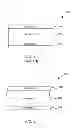
FIG. 1 is a cross section of a prior art bond formed between a first substrate and a second substrate.
FIG. 2 is a cross section illustration of a bond between a first substrate, a second substrate using laser ablation in accordance with one embodiment described in the specification.
FIG. 3 is a cross section illustration of another bond between a first substrate, the second substrate using laser ablation in accordance with one embodiment described in the specification.
FIG. 4 is a cross section illustration of yet another bond 400 between the first substrate, a second substrate using laser ablation in accordance with one embodiment described in the specification.
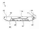
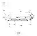
FIG. 5 is a cross sectional view of housing for a portable electronic device that can include a bond that can be formed with laser ablation.
FIG. 6 is flow chart of method steps for bonding a first and a second substrate together using laser ablation to pretreat the substrates.
DETAILED DESCRIPTION OF SELECTED EMBODIMENTS
Representative applications of methods and apparatus according to the present application are described in this section. These examples are being provided solely to add context and aid in the understanding of the described embodiments. It will thus be apparent to one skilled in the art that the described embodiments may be practiced without some or all of these specific details. In other instances, well known process steps have not been described in detail in order to avoid unnecessarily obscuring the described embodiments. Other applications are possible, such that the following examples should not be taken as limiting.
In the following detailed description, references are made to the accompanying drawings, which form a part of the description and in which are shown, by way of illustration, specific embodiments in accordance with the described embodiments. Although these embodiments are described in sufficient detail to enable one skilled in the art to practice the described embodiments, it is understood that these examples are not limiting; such that other embodiments may be used, and changes may be made without departing from the spirit and scope of the described embodiments.
Often a bond between a first substrate and a second substrate can have a limited bond strength. The bond strength can be limited because of substrate choice and because of adhesive bonding characteristics between a selected adhesive and the first and/or the second substrate. For example an affinity between the adhesive and the first surface can be relatively poor reducing a resulting bond strength between the first and the second substrates. In some designs, there may be little flexibility in adhesive choice because of operating conditions or assembly limitations, for example.
In one embodiment a bond surface on the first substrate can be ablated by a laser. The ablation can increase the average surface roughness to a predetermined amount. In another embodiment, the first substrate can be formed from a filled polymer resin. Laser ablation of a filled polymer resin can remove a smooth skin on the first substrate that can be a result of a molding (such as injection molding) operation and can expose at least a portion of the filler material included in the filled resin polymer. In another embodiment, a bond surface on the first and the second substrates can be laser ablated prior to an application of an adhesive to bond the first substrate to the second substrate.
FIG. 1 is a cross section of a prior art bond 100 formed between a first substrate 102 and a second substrate 106 with an adhesive 104. The first and the second substrates 102, 106 can be formed from any appropriate material. For example, the substrates 102, 106 can be polymers such as filled and un-filled resins, metallic substrates such as aluminum, titanium, metal alloys, formed metal such as formed sheet metal, or other materials such as wood or glass. Adhesives 104 can be disposed between the first substrate 102 and the second substrate 106 to bond the substrates together. Adhesives 104 can be pressure sensitive, thermo or UV curing or any other technically feasible adhesive. In some designs, however adhesive choices may be limited due to manufacturing (limitations on the line) or operating constraints (such as operating temperature extremes or required operating humidity). As a result, a bond may be limited in strength especially when the selected adhesive 104 can have a relatively poor bond strength with either the first substrate 102 or the second substrate 106 or, in some cases, poor bond strength with both substrates.
FIG. 2 is a cross section illustration of a bond 200 between a first substrate 202, a second substrate 206 and an adhesive 204 in accordance with one embodiment described in the specification. The first substrate 202 and the second substrate 206 can be substrates as described above in FIG. 1. Bond areas on first substrate 202 and second substrate 206 can be treated with laser ablation to enhance the strength of a bond near the area of the laser ablation. The bond area can be an area on a first surface of the first substrate that is configured to receive the adhesive 204. Similarly, the bond area on the second substrate can be an area on a first surface of the second substrate that is configured to receive the adhesive 204.
Laser ablation can increase a surface roughness on the bond areas of the first and second substrates, and thereby increase bond strength in the bond areas. In one embodiment, laser ablation can increase an average surface roughness of the bond area to a predetermined amount. In one embodiment, first substrate can be molded from composite material such as a filled polymer resin. Oftentimes, molded composite parts can include a relatively smooth outer layer relatively rich in resin material, especially when compared to the bulk of the molded part. Laser ablation can increase the average roughness of the outer layers of molded composite parts.
Laser ablation of the bond areas of the first and the second substrates can provide more adhesive choices to the designer. The bond performance, in this example, is no longer limited to the bond strength between the adhesive 104 and the first substrate 102. Laser ablation of the first substrate can alter surface roughness, surface chemistry and surface composition and thereby affect the material in contact with adhesive 204. Thus, in some embodiments, bond strength can be increased substantially by laser ablation.
FIG. 3 is a cross section illustration of a bond 300 between a first substrate 302, the second substrate 206 formed with an adhesive 304 in accordance with one embodiment described in the specification. In this embodiment, the second substrate 206 can be as described in FIG. 2. In one embodiment, the first substrate 302 can be a composite such as a filled polymer resin. Filler material 303 is schematically shown with first substrate 302. In this example, the first substrate 302 is laser ablated in a bond area that will receive the adhesive 304. As described above, laser ablation can increase the average roughness of the first substrate 302. In this example, since first substrate 302 is a composite, laser ablation can expose filler material of the composite substrate. In yet another embodiment, the adhesive 204 can have a higher affinity for the filler material 303 than the first substrate 302; thus, exposing the filler material can increase bond strength. Adhesive 304 can be selected to bond first ablated substrate 302 to second ablated substrate 206.
FIG. 4 is a cross section illustration of a bond 400 between the first substrate 302, a second substrate 406 formed with an adhesive 404 in accordance with one embodiment described in the specification. The first substrate 302 can be as described above in FIG. 3. In this embodiment, the second substrate 406 can also be a composite, similar to the first substrate 302. Both bond surfaces of the first substrate 302 and the second substrate 406 can be laser ablated to enhance bond strength. In one embodiment, bond surfaces can be less than the entire first or second substrate 302, 406 respectively. Filler material 403 is shown schematically within second substrate 406. Adhesive 404 can be applied to either substrate (first substrate 302 or second substrate 406) in the laser ablated areas to bond the substrates together.
FIG. 5 is a cross sectional view of housing 500 for a portable electronic device that can include a bond that can be formed with laser ablation. The housing 500 can include a front cover 502 and a rear cover 504. The housing 500 can contain components related to the portable electronic device such as a display 520, a processor 524 and a battery 522. In one embodiment, front cover 502 can be substantially transparent and allow at least a portion of the display 520 to be seen through front cover 502. The processor 524 can be configured to control the display 520 and display images on the display 520 for the user. The battery 522 can provide power for the processor 524 and the display 520.
The rear cover 504 can include at least one opening 510 that can receive the processor 524, the battery 522 and the display 520. In one embodiment, the rear cover 504 can include a mounting feature 530 that can be integral to rear cover 504, or can be formed of a material different from the rear cover 504 and secured in place with any technically feasible means such glue, epoxy, welding or the like. The front cover 502 can be configured to substantially fit within at least one opening 510 in the front cover 502. At least one bond area is shown within area 506. In one embodiment, mounting feature 530 can be laser ablated prior to the application of an adhesive 532 to the mounting feature 530. Front cover 502 can be affixed to the adhesive 532. In one embodiment, bond areas on the front cover 502 can be laser ablated prior to the application of adhesive 532.
FIG. 6 is flow chart 600 of method steps for bonding a first and a second substrate together using laser ablation to pretreat the substrates. Persons skilled in the art will understand that any system configured to perform the method steps in any order is within the scope of this description. The method begins in step 602, where a first bond surface of the first substrate can be laser ablated. In one embodiment, the laser ablation can be limited to a bond area less than an entire area of the first substrate. The method can proceed to step 604, when a bond area of the second substrate is laser ablated. Step 604 can be an optional step (as shown with dashed lines). In other words, each substrate need not be laser ablated, especially when laser ablating only one substrate can provide a bond of sufficient strength. In step 606, an adhesive is applied to the bond area. In one embodiment, the adhesive is only applied to the bond area of one substrate (that is, either the first substrate or the second substrate, but not both). In step 608, the first substrate is bonded to the second substrate through the adhesive and the method ends. In one embodiment, the applied adhesive is placed in contact with the bond surfaces on both the first and the second substrates.
The various aspects, embodiments, implementations or features of the described embodiments can be used separately or in any combination. Various aspects of the described embodiments can be implemented by software, hardware or a combination of hardware and software. The described embodiments can also be embodied as computer readable code on a computer readable medium for controlling manufacturing operations or as computer readable code on a computer readable medium for controlling a manufacturing line. The computer readable medium is any data storage device that can store data which can thereafter be read by a computer system. Examples of the computer readable medium include read-only memory, random-access memory, CD-ROMs, HDDs, DVDs, magnetic tape, and optical data storage devices. The computer readable medium can also be distributed over network-coupled computer systems so that the computer readable code is stored and executed in a distributed fashion.
The foregoing description, for purposes of explanation, used specific nomenclature to provide a thorough understanding of the described embodiments. However, it will be apparent to one skilled in the art that the specific details are not required in order to practice the described embodiments. Thus, the foregoing descriptions of specific embodiments are presented for purposes of illustration and description. They are not intended to be exhaustive or to limit the described embodiments to the precise forms disclosed. It will be apparent to one of ordinary skill in the art that many modifications and variations are possible in view of the above teachings.
Claims
What is claimed is:1. A method for bonding a first substrate to a second substrate, with an adhesive comprising:
preparing a first bond surface on the first substrate, the first bond surface less than the entire first substrate, by laser ablating the first bond surface;
disposing an adhesive on a first bond surface of the second substrate, wherein the first bond surface of the second substrate substantially corresponds to the first bond surface on the first substrate; and
bonding the second substrate to the first substrate by placing the adhesive disposed on the first bond surface of the second substrate in direct contact with the first bond surface of the first substrate.
2. The method of claim 1, wherein the average roughness of the first bond surface of the first substrate is increased to a predetermined average amount.
3. The method of claim 1, wherein the first substrate is a filled polymer resin.
4. The method of claim 3, wherein the laser ablation exposes filler material from the filled polymer resin.
5. The method of claim 4, wherein the second substrate is a substantially clear.
6. A method for bonding a first substrate to a second substrate, with an adhesive comprising:
preparing a first bond surface on the first substrate, the first bond surface less than the entire first substrate, by laser ablating the first bond surface on the first substrate;
preparing a first bond surface on the second substrate, the first bond surface less than the entire second substrate, by laser ablating the first bond surface on the second substrate;
disposing an adhesive on a first bond surface of the second substrate, wherein the first bond surface of the second substrate substantially corresponds to the first bond surface of the first substrate; and,
positioning the adhesive to be in direct contact with the first bond surface of the first substrate.
7. The method of claim 6, wherein at least one of the first substrate or the second substrate the first substrate comprises a filled polymer resin and wherein the laser ablation removes a smooth resin finish and exposes at least a portion of the filler material
8. A housing for a portable electronic device comprising:
a rear cover including at least one opening and a laser ablated first bonding surface proximate to the at least one opening, wherein the rear cover is configured to contain electrical components for the portable electronic device;
a front cover configured to be substantially clear and sized to substantially fit into the at least one opening of the rear cover and configured to include a first bonding surface substantially matching the shape of the first bonding surface of the rear cover;
a display unit disposed within the rear cover, wherein the display unit is positioned behind the front cover so that at least a portion of the display is visible through the front cover; and,
an adhesive applied on the first bonding surface of the rear cover, wherein the adhesive is placed in direct contact with the first bonding surface of the front cover.
9. The housing of claim 8, wherein the first bonding surface of the rear cover comprises a filled resin polymer.
10. The housing of claim 9, wherein the laser ablating removes at least a portion of the surface of the filled resin polymer.
11. The housing of claim 10, wherein the laser ablating exposes filler material included in the filled resin polymer.
12. The housing of claim 8, wherein the laser ablating increases an average roughness of the first bonding surface of the rear cover to a predetermined amount.
13. The housing of claim 8, wherein the first bonding surface of the front cover is laser ablated prior to the application of the adhesive.
14. A bonded assembly comprising:
a first substrate with a laser ablated first bonding surface, wherein the first bonding surface is less than the entire first substrate;
a second substrate with a first bonding surface corresponding to the shape of the first bonding surface of the first substrate; and
an adhesive layer disposed between the first bonding surface of the first substrate and first bonding surface of the second substrate.
15. The bonded assembly of claim 14, wherein the laser ablation increases the average surface roughness of the first bonding surface of the first substrate to a predetermined amount.
16. The bonded assembly of claim 15, wherein the first bonding surface comprises a filled polymer resin.
17. The bonded assembly of claim 16, wherein the laser ablation exposes at least a portion of the filler material in the filled polymer resin.
18. The bonded assembly of claim 14, wherein the first bonding surface of the second substrate is laser ablated prior to bonding with the first substrate.
19. The bonded assembly of claim 18, wherein the second substrate comprises a resin filled polymer.
20. The bonded assembly of claim 19, wherein the laser ablating exposes filler material on at least one of the first or the second substrates.
Images & Drawings included:


Sources:
- United States Patent and Trademark Office - verify current appl. status at the USPTO↗
Recent applications in this class:
- » 20250051613 2025-02-13
PLASMA MODIFICATION OF ADHESIVE AND SUBSTRATE SURFACES FOR USE IN ADHESIVE JOINT APPLICATIONS - » 20250026963 2025-01-23
TEMPORARY SHEET BONDING METHOD AND APPARATUS - » 20240360339 2024-10-31
METHOD FOR FORMING A BOND BETWEEN TWO SUBSTRATES OF A DEVICE; DEVICE OBTAINABLE BY THE METHOD; A MICROFLUIDIC DEVICE; AND USE OF THE DEVICE - » 20240294805 2024-09-05
LIQUID MOISTURE CURABLE POLYURETHANE WITH IMPROVED ADHESION TO ALUMINUM - » 20240294804 2024-09-05
METHOD OF BONDING SUBSTRATES - » 20240150617 2024-05-09
METHOD FOR BONDING TWO HYDROPHILIC SURFACES - » 20240067847 2024-02-29
System for curing a patch - » 20240052204 2024-02-15
ADHESIVE BONDING METHOD FOR AUTOMATED PROCESSES - » 20230407136 2023-12-21
Adjustable hybrid PSA/structural adhesive bonds by patterned surface-initiated cure - » 20230399544 2023-12-14
VULCANIZED RUBBER SURFACE TREATMENT AGENT, METHOD OF PRODUCING ADHESIVE STRUCTURE, ADHESIVE STRUCTURE, AND TIRE
Recent applications for this Assignee:
- » 20250175945 2025-05-29
PAGING ALERT DESIGN FOR NON-TERRESTRIAL NETWORKS (NTNS) - » 20250175727 2025-05-29
IN-EAR HEADPHONE - » 20250175664 2025-05-29
User Interfaces For Video Editing Application On Touch Screen Device - » 20250173989 2025-05-29
Intelligently Placing Labels - » 20250173980 2025-05-29
Synchronized, Interactive Augmented Reality Displays for Multifunction Devices - » 20250168760 2025-05-22
USER EQUIPMENT INVOLVED DISTRIBUTED NON-ACCESS STRATUM - » 20250168655 2025-05-22
CONTROL MESSAGING FOR MULTI-BEAM COMMUNICATIONS - » 20250168566 2025-05-22
LOCATING WIRELESS DEVICES - » 20250168272 2025-05-22
RANGING BETWEEN MOBILE DEVICES - » 20250168095 2025-05-22
UNIFORM COMMUNICATION PROTOCOLS FOR COMMUNICATION BETWEEN CONTROLLERS AND ACCESSORIES