Vehicle starting apparatus
US20140076259A1
2014-03-20
14/115,411
2011-09-07
✅ Patent granted
US 9,394,873 B2
2016-07-19
WO; PCT/JP2011/070343; 20110907
WO; WO2013/035168; 20130314
Stephen K Cronin | Xiao Mo
Sughrue Mion, PLLC
2032-06-29
Abstract:
There is provided a vehicle starting apparatus that reduces vibration of an engine caused when the engine starts so that vibration of the vehicle can be decreased. A vehicle starting apparatus according to the present invention is provided with an engine starting apparatus that starts an engine mounted in a vehicle, wherein before the engine is ignited, the engine starting apparatus makes a cranking rotation speed of the engine lower than a rotation speed corresponding to the resonance frequency of the engine, and after the engine has been ignited, the engine starting apparatus increases the rotation speed of the engine up to a rotation speed that is the same as or higher than said rotation speed corresponding to the resonance frequency.
Assignee:
- MITSUBISHI ELECTRIC CORPORATION 16,560 🇯🇵 TOKYO, Japan
- MITSUBISHI ELECTRIC CORPORATION 3,549 🇯🇵 Chiyoda-ku, Tokyo, Japan
Applicant:
Interested in similar patents?
Get notified when new applications in this technology area are published.
Classification:
F02N15/00 » CPC main
Other power-operated starting apparatus; Component parts, details, or accessories, not provided for in, or of interest apart from groups -
F02D2250/28 » CPC further
Engine control related to specific problems or objectives Control for reducing torsional vibrations, e.g. at acceleration
F02N11/0848 » CPC further
Starting of engines by means of electric motors; Circuits or control means specially adapted for starting of engines with means for detecting successful engine start, e.g. to stop starter actuation
F02N2011/0885 » CPC further
Starting of engines by means of electric motors; Circuits or control means specially adapted for starting of engines; Components of the circuit not provided for by previous groups Capacitors, e.g. for additional power supply
F02N11/087 » CPC further
Starting of engines by means of electric motors; Circuits or control means specially adapted for starting of engines Details of the switching means in starting circuits, e.g. relays or electronic switches
F02N11/04 » CPC further
Starting of engines by means of electric motors the motors being associated with current generators
F02N11/08 IPC
Starting of engines by means of electric motors Circuits or control means specially adapted for starting of engines
F02N2011/0896 » CPC further
Starting of engines by means of electric motors; Circuits or control means specially adapted for starting of engines; Components of the circuit not provided for by previous groups Inverters for electric machines, e.g. starter-generators
F02N2200/041 » CPC further
Parameters used for control of starting apparatus said parameters being related to the starter motor Starter speed
F02N2200/042 » CPC further
Parameters used for control of starting apparatus said parameters being related to the starter motor Starter torque
F02N2200/044 » CPC further
Parameters used for control of starting apparatus said parameters being related to the starter motor Starter current
F02N2300/102 » CPC further
Control related aspects of engine starting characterised by the control output, i.e. means or parameters used as a control output or target Control of the starter motor speed; Control of the engine speed during cranking
F02N11/10 » CPC further
Starting of engines by means of electric motors Safety devices
F02N15/08 » CPC further
Other power-operated starting apparatus; Component parts, details, or accessories, not provided for in, or of interest apart from groups - ; Gearing between starting-engines and started engines; Engagement or disengagement thereof the gearing being of friction type
Description
TECHNICAL FIELD
The present invention relates to a vehicle starting apparatus that starts an engine mounted in a vehicle.
BACKGROUND ART
In recent years, in order to raise gasoline mileage and conformity to the environment standard, there has been developed a vehicle starting apparatus that is equipped with a power-generation motor and performs a so-called idling stop in which the engine is stopped when the vehicle stops and the engine is restarted by use of the power-generation motor when the vehicle starts. Because the vehicle power-generation motor utilized in such control as described above needs to be small-size, low-cost, and high-torque; therefore, in many cases, a coil-magnetic-field power-generation motor is utilized therefor.
In an idling stop system utilizing such a coil-magnetic-field power-generation motor, in order to start the engine as early as possible when the engine starts, ignition may be implemented, as disclosed in Patent Document 1, by applying maximal torque control to the starting apparatus so as to crank the engine.
PRIOR ART REFERENCE
Patent Document
[Patent Document 1] Japanese Patent Application Laid-Open No. 2003-113763
DISCLOSURE OF THE INVENTION
Problems to be Solved by the Invention
However, in a conventional apparatus disclosed in Patent Document 1, because when the engine is being cranked, the cranking rotation speed falls within the resonance frequency range, vibration of the engine is enlarged and hence vibration of the vehicle is increased; thus, discomfort may be given to the driver or the fellow passengers.
The present invention has been implemented in order to solve the foregoing problem in a control apparatus for a vehicle starting apparatus; the objective thereof is to provide a vehicle starting apparatus that reduces vibration of an engine caused when the engine starts so that vibration of the vehicle can be decreased.
Means for Solving the Problems
A vehicle starting apparatus according to the present invention is provided with an engine starting apparatus that starts an engine mounted in a vehicle, wherein before the engine is ignited, the engine starting apparatus makes a cranking rotation speed of the engine lower than a rotation speed corresponding to the resonance frequency of the engine, and after the engine has been ignited, the engine starting apparatus increases the rotation speed of the engine up to a rotation speed that is the same as or higher than said rotation speed corresponding to the resonance frequency.
Advantage of the Invention
A vehicle starting apparatus according to the present invention can reduce vibration of an engine caused when the engine starts so that vibration of the vehicle can be decreased.
BRIEF DESCRIPTION OF THE DRAWINGS
FIG. 1 is an explanatory diagram for a vehicle system equipped with a vehicle starting apparatus according to Embodiment 1 of the present invention;
FIG. 2 is an explanatory diagram representing the details of a vehicle starting apparatus according to Embodiment 1 of the present invention;
FIG. 3 is a flowchart for explaining the operation of a vehicle starting apparatus according to Embodiment 1 of the present invention; and
FIG. 4 is a flowchart for explaining the operation of a vehicle starting apparatus according to Embodiment 2 of the present invention.
BEST MODE FOR CARRYING OUT THE INVENTION
Embodiment 1
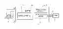
Hereinafter, a vehicle starting apparatus according to Embodiment 1 of the present invention will be explained with reference to the drawings. FIG. 1 is an explanatory diagram for a vehicle system equipped with a vehicle starting apparatus according to Embodiment 1 of the present invention. In FIG. 1, an engine starting apparatus 1 is configured with an inverter 11 and a rotating electric machine 12. The engine starting apparatus 1 is provided with a control apparatus 111 that controls the inverter 11.
The rotating electric machine 12 is coupled with an engine 3 through the intermediary of a driving power transfer unit 4 such as a belt. When the engine 3 is started, the engine starting apparatus 1 is supplied with electric power by a power source apparatus 2, which is a battery or a capacitor, and makes the rotating electric machine 12 operate as a motor so that the engine 3 is rotated by the intermediary of the driving power transfer unit 4. A command of operation mode is instructed through a controller, a key switch, or the like of an external idling stop system, which is unillustrated in FIG. 1; the engine starting apparatus 1 is operated in a drive mode according to the command.
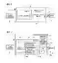
FIG. 2 is an explanatory diagram representing the details of a vehicle starting apparatus according to Embodiment 1 of the present invention. In FIG. 2, described above, the engine starting apparatus 1 is configured with the inverter 11 and the rotating electric machine 12 and operates as a power-generation motor, as described later. The rotating electric machine 12 is formed of a coil-magnetic-field power-generation motor and is provided with an armature winding 122 provided in the stator thereof and a magnetic-field winding 121 provided in the rotor thereof. A rotation sensor 123 that detects the rotation speed of the rotor is provided in the power-generation motor 12.
The inverter 11 includes a magnetic-field electric power conversion unit 112 provided with an electric-power conversion device that controls the electric power of the magnetic-field winding 121, an armature electric power conversion unit 113 provided with an electric-power conversion device that controls the electric power of the armature winding 122, the control apparatus 111 that issues on/off commands for the respective electric-power conversion devices of the magnetic-field electric power conversion unit 112 and the armature electric power conversion unit 113, and a current sensor 114 for detecting a magnetic-field current.
The magnetic-field electric power conversion unit 112 operates in response to the on/off command for the electric-power conversion device from the control apparatus 111 and controls, through PWM control, the magnetic-field current that flows in the magnetic-field winding 121. In general, the magnetic-field electric power conversion unit 112 is formed of a half bridge circuit configured with MOS-type field-effect transistors (MOSFETs), which function as electric-power conversion devices.
In general, the armature electric power conversion unit 113 is formed of three-phase bridge circuit configured with MOSFETs, which function as electric-power conversion devices. When the engine starts, the armature electric power conversion unit 113 operates, as an inverter, in response to the on/off command for the electric-power conversion device from the control apparatus 111, converts DC power of the power source apparatus 2 into three-phase AC power so as to make an armature current flow in the armature coil 122 of the rotating electric machine 12, so that the rotating electric machine 12 operates as a motor. In some cases, the engine starting apparatus 1 makes the rotating electric machine 12 operate as an electric power generator. In this case, in response to the on/off command for the electric-power conversion device from the control apparatus 111, the armature electric power conversion unit 113 operates as a converter so as to convert three-phase AC power generated across the armature winding 122 into DC power and to supply the DC power to the power source apparatus 2 and other electric loads.
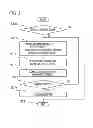
Next, there will be explained the operation of the vehicle starting apparatus, according to the present invention, that is configured as described above. FIG. 3 is a flowchart for explaining the operation of a vehicle starting apparatus according to Embodiment 1 of the present invention. In FIG. 3, at first, in the step S301, it is determined whether or not a driving command has been issued from the controller, the key switch, or the like of the idling stop system. In the case where the driving command has been issued (YES), the step S301 is followed by the step S311. In the case where the driving command has not been issued (NO), no driving processing is implemented; thus, the processing is ended.
Because in FIG. 3, only the process related to the present invention is represented, the explanations for other processes are omitted; however, in the case where even when a driving command has issued, the engine starting apparatus is abnormal or the power-source voltage is out of a specified range, no driving is performed.
In the step S311, in accordance with the power-source voltage, the control apparatus 111 calculates the magnetic-field current and the armature current for a target starting apparatus rotation speed or the conduction phase angle for that armature current. The target starting apparatus rotation speed here signifies a target rotation speed of the rotating electric machine 12 at a time when the rotating electric machine 12 of the engine starting apparatus 1 cranks the engine 3 before ignition is implemented. In this situation, it is assumed that the target starting apparatus rotation speed calculated by the control apparatus 111 is smaller than the rotation speed thereof at a time when vibration whose frequency coincides with the resonance frequency of the engine 3 occurs in the engine 3.
As is well known, in the case where when being cranked before ignition is implemented, the engine 3 rotates at a specified rotation speed, the frequency of the vibration of the engine 3 caused by the rotation coincide with the inherent resonance frequency of the engine 3 and hence the engine 3 largely vibrates. The engine rotation speed that causes the engine 3 to vibrate at the resonance frequency is inherent to the engine, depending on the specification of the engine 3 or the structure of the vehicle in which the engine 3 is mounted, and can preliminarily be known through a calculation or an experiment.
Accordingly, in the step S311, in order to prevent the engine 3 from vibrating at the resonance frequency, the control apparatus 111 sets the target starting apparatus rotation speed of the rotating electric machine 12, which cranks the engine 3, at a rotation speed that is lower than the foregoing specific rotation speed so that the engine 3 rotates at a rotation speed that is lower than the specific rotation speed of the preliminarily obtained specific rotation speed of the engine 3; then, in accordance with the power-source voltage, the control apparatus 111 calculates the values of the magnetic-field current and the armature current for the target starting apparatus rotation speed. In this situation, it goes without saying that it may be allowed that instead of calculating the values of the magnetic-field current and the armature current, the respective conduction phase angles of the electric-power conversion devices for obtaining those current values are calculated.
Subsequently, in the step S312, based on the foregoing calculation results, the control apparatus 111 issues to the magnetic-field electric power conversion unit 112 the on/off commands for the electric-power conversion devices thereof; then, based on the commands, the magnetic-field electric power conversion unit 112 performs energization control of the magnetic-field current to the magnetic-field winding 121. As the controlling method for the magnetic-field current energization, there may be performed PI control or there may be performed control in which in order to raise the responsiveness of the magnetic-field current, the conduction rate of PWM control is set to 100[%] until the magnetic-field current reaches the target magnetic-field current.
Subsequently, in the step S313, based on the foregoing calculation results, the control apparatus 111 issues to the armature electric power conversion unit 113 the on/off commands for the electric-power conversion devices thereof; then, based on the commands, the armature electric power conversion unit 113 performs control the energization of the armature winding 122. In this situation, the armature current is controlled based on the conduction phase angle.
Through the magnetic-field current control in the step S312 and the armature current control in the step S313, the rotating electric machine 12 rotates at a speed that is lower than the foregoing specific rotation speed, and cranks the engine 3; in the step S315, it is determined whether or not the engine 3 has been ignited due to the cranking. Whether or not the engine 3 has been ignited may be determined based on the engine rotation speed or a change in the rotation speed or may be determined by electrically detecting that an ignition signal has been generated. In the case where it is determined in the step S315 that the engine 3 has been ignited (YES), the step S315 is followed by the step S314, where the engine 3 comes into the normal driving mode and the torque increases, so that the starting of the vehicle is completed.
The maximum value of the rotation speed at which the engine starting apparatus 1 can crank the engine 3 is set to be higher than a rotation speed corresponding to the foregoing resonance frequency of the engine 3. As described above, because the engine rotation speed at which the engine starting apparatus 1 can crank the engine 3 by itself is higher than a rotation speed corresponding to the resonance frequency of the engine, it is made possible that the increase in the torque after the ignition of the engine can largely accelerate the engine rotation speed and hence it is made possible to make the engine vibration frequency pass through the engine resonance frequency range in a short time; therefore, the vibration of the engine due to the resonance can be reduced and hence the vibration of the vehicle can be suppressed.
The torque exerted on the engine 3 by the engine starting apparatus 1 after the ignition of the engine is the maximum torque of the engine starting apparatus 1, i.e., the rotating electric machine 12. As described above, because the torque, accelerated after the ignition of the engine, becomes maximum, the acceleration of the engine rotation speed due to the increase in the torque after the ignition of the engine can further be enlarged. Accordingly, the engine vibration frequency can pass through the engine resonance frequency in a shorter time; therefore, the vibration of the engine due to the resonance can be reduced and hence the vibration of the vehicle can be suppressed.
In the case where it is determined in the step S315 that the engine 3 has not been ignited (NO), the step S315 is followed by the step S311; then, the processes from the step S311 to the step S315 are repeated until the ignition of the engine 3 is recognized.
As described above, the vehicle starting apparatus according to Embodiment 1 of the present invention suppresses the engine from vibrating when the engine is restarted; therefore, optimum restarting control in accordance with the power-source voltage can be implemented.
Embodiment 2
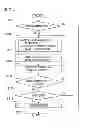
In Embodiment 2, rotation speed feedback control is also implemented, in comparison to Embodiment 1. The other configurations are the same as those in Embodiment 1. FIG. 4 is a flowchart for explaining the operation of a vehicle starting apparatus according to Embodiment 2 of the present invention. Hereinafter, different points between Embodiments 1 and 2 will mainly be explained.
In FIG. 4, in the step S316, the rotation speed of the rotating electric machine 12 detected by the rotation sensor 123 and the target rotation speed are compared with each other, and rotation speed feedback control is implemented so that the difference between the rotation speed of the rotating electric machine 12 and the target rotation speed is under a given threshold value; in the case where the rotation speed of the rotating electric machine 12 has reached the target rotation speed (YES), the step S316 is followed by the step S315. The target rotation speed here signifies the target starting apparatus rotation speed in the step S311 explained in Embodiment 1.
In the case where it is determined in the step S316 that the rotation speed of the rotating electric machine 12 has not reached the target rotation speed (NO), the step S316 is followed by the step S311; then, the processes from the step S311 to the step S316 are repeated so that the rotation speed of the rotating electric machine 12 reaches the target rotation speed.
As described above, the vehicle starting apparatus according to Embodiment 2 of the present invention makes it possible to perform optimum rotation speed control in accordance with the power-source voltage. Moreover, feedback control raises the accuracy of the rotation speed and makes it possible to reduce vibration.
INDUSTRIAL APPLICABILITY
A vehicle starting apparatus according to the present invention can be applied to the field of the automobile industry, especially, to the field of an engine control apparatus.
DESCRIPTION OF REFERENCE NUMERALS
- 1: engine starting apparatus
- 2: battery
- 3: engine
- 4: driving power transfer unit
- 11: inverter
- 12: electric rotating machine
- 111: control apparatus
- 112: magnetic-field electric power conversion unit
- 113: armature electric power conversion unit
- 114: magnetic-field current sensor
- 121: magnetic-field coil
- 122: armature coil
- 123: rotation sensor
Claims
1. A vehicle starting apparatus provided with an engine starting apparatus that starts an engine mounted in a vehicle, wherein before the engine is ignited, the engine starting apparatus makes a cranking rotation speed of the engine lower than a rotation speed corresponding to the resonance frequency of the engine, and after the engine has been ignited, the engine starting apparatus outputs more than it outputs before the engine is ignited, so that a rotation speed of the engine is more quickly accelerated up to said rotation speed corresponding to the resonance frequency.
2. The vehicle starting apparatus according to claim 1, wherein as a maximum value of the rotation speed at which the cranking can be implemented, the engine starting apparatus has a value that is larger than the value of said rotation speed corresponding to the resonance frequency of the engine.
3. The vehicle starting apparatus according to claim 1, wherein torque exerted on the engine by the engine starting apparatus after the ignition of the engine is the maximum torque thereof.
4. The vehicle starting apparatus according to claim 1, wherein the engine starting apparatus has a rotation detection unit that detects a rotation speed of the engine and performs rotation speed control in a feedback manner, based on detection of the rotation speed by the rotation detection unit.
5. The vehicle starting apparatus according to claim 1, wherein the engine starting apparatus starts the engine by the intermediary of a belt.
6. The vehicle starting apparatus according to claim 1, wherein the engine starting apparatus is provided with a power-generation motor having a magnetic-field winding and an armature winding, a magnetic-field electric power conversion unit that controls a magnetic-field current in the magnetic-field winding, an armature electric power conversion unit that controls an armature current in the armature winding, and a control apparatus that controls the magnetic-field electric power conversion unit and the armature electric power conversion unit.
Images & Drawings included:
Sources:
- United States Patent and Trademark Office - verify current appl. status at the USPTO↗
Similar patent applications:
- » 20190190134
Vehicle starting apparatus - » 20120283937
Vehicle start control apparatus - » 10422414
Vehicle engine starting apparatus - » 20140053684
Vehicle engine starting apparatus - » 20050246070
Vehicle remote starting apparatus and method for executing registration process - » 20080092841
Engine start control apparatus, engine start control method, and motor vehicle equipped with engine start control apparatus - » 14325938
Portable vehicle battery jump start apparatus with safety protection - » 20120318227
In-vehicle engine start control apparatus - » 20090115250
Starting button apparatus for vehicle - » 20100010715
Improper start preventing apparatus for vehicle
Recent applications in this class:
- » 20150330350 2015-11-19
STARTER FOR PISTON ENGINE ALLOWING A MITIGATION OF THE RESISTIVE TORQUE - » 20140236461 2014-08-21
METHOD AND START ASSISTING SYSTEM FOR FACILITATING START ACTIVITIES OF A VEHICLE - » 20140102409 2014-04-17
Method for starting an internal combustion engine - » 20140046578 2014-02-13
Supporting a driver of a motor vehicle in utilizing an automatic start-stop system - » 20130333655 2013-12-19
Method of cold starting an internal combustion engine in hybrid applications - » 20130291830 2013-11-07
Methods and systems for engine starting during a shift - » 20130269644 2013-10-17
Start control system and vehicle - » 20130220256 2013-08-29
Controller for engine starter - » 20130180490 2013-07-18
Engine starting device and engine starting method - » 20130174801 2013-07-11
VEHICULAR STARTER SOLENOID
Recent applications for this Assignee:
- » 20250294680 2025-09-18
POWER MODULE - » 20250293740 2025-09-18
WIRELESS COMMUNICATION SYSTEM - » 20250293196 2025-09-18
SEMICONDUCTOR DEVICE AND MANUFACTURING METHOD THEREOF - » 20250292172 2025-09-18
PROCESS PLAN PREPARATION ASSISTANCE APPARATUS, PROCESS PLAN PREPARATION ASSISTANCE SYSTEM, AND PROCESS PLAN PREPARATION ASSISTANCE METHOD - » 20250291113 2025-09-18
OPTICAL TERMINATOR, OPTICAL WAVELENGTH FILTER, AND EXTERNAL CAVITY LASER LIGHT SOURCE - » 20250290867 2025-09-18
SEMICONDUCTOR INSPECTION APPARATUS AND METHOD OF MANUFACTURING SEMICONDUCTOR DEVICE - » 20250290765 2025-09-18
INFORMATION PROCESSING DEVICE, INFORMATION PROCESSING METHOD, AND IMAGE PROJECTING SYSTEM - » 20250289592 2025-09-18
SPACE SITUATIONAL AWARENESS BUSINESS DEVICE AND SPACE TRAFFIC BUSINESS DEVICE - » 20250287683 2025-09-11
SEMICONDUCTOR DEVICE - » 20250287624 2025-09-11
POWER SEMICONDUCTOR DEVICE