METHOD AND SYSTEM OF OPTIMIZED STEAM-ASSISTED GRAVITY DRAINAGE WITH OXYGEN ("SAGDOXO") FOR OIL RECOVERY
US20140076555A1
2014-03-20
14/083,106
2013-11-18
Abstract:
A steam assisted gravity drainage with injected oxygen (SAGDOX) process to recover hydrocarbons in a hydrocarbon reservoir including:
-
- (a) starting the SAGDOX process at a first oxygen to steam ratio;
- (b) measuring a produced water to oil ratio (v/v) PWOR associated with the first oxygen to steam ratio;
- (c) adjusting the oxygen to steam ratio to obtain a predetermined PWOR; and
- (d) continuing steps (a) to (c) until a target PWOR is obtained improving the hydrocarbon recovery rate.
Assignee:
- NEXEN ENERGY ULC 8 🇨🇦 Calgary, Canada
Interested in similar patents?
Get notified when new applications in this technology area are published.
Classification:
E21B43/2406 » CPC main
Methods or apparatus for obtaining oil, gas, water, soluble or meltable materials or a slurry of minerals from wells; Enhanced recovery methods for obtaining hydrocarbons using heat, e.g. steam injection Steam assisted gravity drainage [SAGD]
E21B43/24 IPC
Methods or apparatus for obtaining oil, gas, water, soluble or meltable materials or a slurry of minerals from wells; Enhanced recovery methods for obtaining hydrocarbons using heat, e.g. steam injection
Description
BACKGROUND OF THE INVENTION
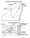
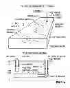
Steam-Assisted Gravity Drainage (“SAGD”) is a commercial thermal Enhanced Oil Recovery (“EOR”) process, using saturated steam injected into a horizontal well 2, where latent heat is used to heat bitumen and lower its viscosity so it drains, by gravity, to an underlaying, parallel, twin horizontal well (i.e. production well 4), completed near the bottom of the reservoir (FIG. 1). The steam injection rate is adjusted to achieve a target pressure. The liquid production rate is adjusted to achieve a target temperature, a few degrees less than saturated steam temperatures, so live steam can't break through to the production well.
Since the process inception in the early 1980's (Butler, R. M., “Thermal Recovery of Oil & Bitumen”, Prentice-Hall, 1991), SAGD has become the dominant, in situ, process to recover bitumen from Alberta's bitumen deposits. Today's SAGD bitumen production, in Alberta, is about 300 K barrels/day (“bbl/d”) (Oil sands Review, (2010)); with installed capacity at about 475 Kbbl/d (ibid). SAGD is now the world's leading thermal EOR process.
FIG. 1 (Prior Art) shows the “traditional” SAGD geometry, using twin, parallel horizontal wells 2, 4, an upper injector well 2 and a lower producer well 4, drilled in the same vertical plane, with a 5 metre spacing between the two wells 2, 4, each well being about 800 metres long, and with the lower (or producer 4) well 1 to 2 metres above the (horizontal) reservoir floor. The SAGD process is started by circulating steam in both wells. After communication is established, the upper well is used to inject steam 6 and the lower well produces hot water and hot bitumen 8. Liquid production is accomplished by natural lift; by gas lift or by submersible pump.
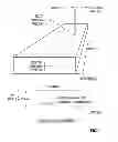
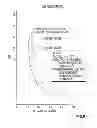
After conversion to normal SAGD operations, a steam chamber 10 forms around the injector well 2 and producter well 4 where the void space is occupied by steam 6. FIG. 2 (Prior Art) shows how SAGD matures. Steam 6 condenses at the boundaries of the chamber, releases latent heat (heat of condensation) and heats bitumen, connate water and the reservoir matrix. Heated bitumen and water 8 drain, by gravity, to the lower production well 4. The steam chamber 10 grows upward and outward as bitumen is drained. A “young” steam chamber 10 has bitumen drainage from steep chamber sides and from the chamber ceiling. When the chamber 10 growth hits the top of the reservoir, ceiling drainage stops, bitumen productivity peaks and the slope of the side walls decreases as lateral growth continues. Heat losses increase (Steam to Oil Ratio (“SOR”) increases) (FIG. 8) as ceiling contact increases and the surface area of the steam chamber increases. Drainage rates slow down as the side wall angle (θ) decreases. Eventually, the economic limit is reached and the end-of-life drainage angle is small (10-20°, as shown in FIG. 2 (Prior Art).
Produced fluids are near saturated steam temperature, so it is only the latent heat of steam that contributes to the process, in the reservoir. But, some of the sensible heat may be capture from surface heat exchangers (a greater fraction at higher temperatures), so a useful rule-of-thumb, for net heat contribution of steam, is 1000 BTU/lb. for the Pressure (“P”) and Temperature (“T”) range of most SAGD projects as best seen in FIG. 3 (Prior Art).
The operational performance of SAGD may be characterized by measurement of the following parameters—saturated steam P and T in the steam chamber (FIG. 2); bitumen productivity; SOR, usually at the well head (“wh”); sub-cool, the T difference between saturated steam and produced fluids; and water recycle ratio (“WRR”), the ratio of produced water to steam injected.
During the SAGD process, the SAGD operator has two choices to make—the sub-cool target T difference and the operating pressure P in the reservoir. A typical sub-cool target T difference of about 10° C. to 30° C. is meant to ensure no live steam breaks through to the production well. Process pressure and temperature are linked as best seen in FIG. 14 (Prior Art) and relate mostly to bitumen productivity and process efficiency. Bitumen viscosity is a strong function of temperature, as best seen in FIG. 5 (Prior Art) bitumen viscosity decreases with a temperature increase. As per the Gravdrain equation, shown in FIG. 6 (Prior Art), SAGD productivity is proportional to the square root of the inverse viscosity (Butler (1991)). Conversely, if P and T are increased, the latent heat control of steam drops rapidly (FIG. 3) and more energy is used to heat the rock matrix and is also lost to the overburden or other non-productive areas. Thus, increased P increases bitumen productivity but harms process efficiency (increases SOR). Because economic returns can be dominated by bitumen productivity, the SAGD operator typically opts to target operating pressures higher than native, hydrostatic reservoir pressures. Despite becoming the dominant thermal EOR process, SAGD has some limitations and detractions. A good SAGD project comprises:
-
- a horizontal well completed near the bottom of the pay zone to effectively collect and produce hot draining fluids.
- injected steam, at the sand face (“sf”) is a high quality.
- process start up is effective and expedient.
- the steam chamber grows smoothly and is contained.
- the reservoir matrix is good quality (porosity fraction (“Φ”)>0.2, initial oil saturation (“Sio”)>0.6, kinematic viscosity (“kv”)>2 dimensions (“2D”)).
- net pay is sufficient (>15 metres thick).
- proper design and control to simultaneously prevent steam breakthrough, prevent injector flooding, stimulate steam chamber growth to productive zones and inhibit water inflows to the steam chamber.
- absence of significant reservoir baffles (e.g. lean zones) or barriers (e.g. shale).
If these musts are not attained or other limitations are experienced, SAGD may be impaired, as follows:
-
- (1) The preferred dominant production mechanism is gravity drainage and the lower production well is horizontal. If the reservoir is highly slanted, a horizontal production well will strand a significant resource.
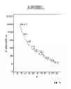
- (2) The SAGD steam-swept zone has a significant residual bitumen content that is not recovered, particularly for heavier bitumens and low pressure steam, as best seen in FIG. 26. FIG. 4 (Prior Art) depicts fractional residual bitumen in pores of bitumen and heavy oil. For example with a 20% residual bitumen (pore saturation) and a 70% initial saturation, the recovery factor is only 71%, not including stranded bitumen below the production well or in the wedge zone between recovery patterns.
- (3) To contain a SAGD steam chamber, the oil in the reservoir must be relatively immobile; SAGD cannot work on heavy (or light) oils with mobility at reservoir conditions. Bitumen is the preferred target.
- (4) Saturated steam cannot vapourize connate water. By definition, the heat energy in saturated steam is not high enough quality (temperature) to vapourize water. Field experience also shows for bitumen pay zones that heated connate is not mobilized sufficiently to be produced in SAGD. Produced Water to Oil ratio (PWOR) is similar to SOR. This makes it difficult for SAGD to breach or utilize lean zone resources.
- (5) The existence of an active water zone—either top water or an interspersed lean zone within the pay zone—may cause operations difficulties for SAGD (Nexen Inc., “Second Quarter Results”, Aug. 4, 2011: Vanderklippe, N. “Long Lake Project Hits Sticky Patch” CTV 2011), or ultimately can cause project failures. Simulation studies concluded that increasing production well stand-off distances can optimize SAGD performance with active bottom waters, including good pressure control to minimize water influx (Akram, F. “Reservoir Simulation Optimizes SAGD”, American Oil and Gas Reporter(AOGR), September 2011).
- (6) Pressure targets cannot (always) be increased to improve SAGD productivity and SAGD economics. If the reservoir is leaky, as pressure is increased beyond native hydrostatic pressures, the SAGD process can lose water or steam to zones outside the SAGD steam chamber. If fluids are lost, the Water Recycle Ratio (“WRR”) decreases and the process requires significant water make-up volumes. If steam is also lost, process efficiency drops and SOR increases. Ultimately, if pressures are too high, if the reservoir is shallow and if the high pressures are retained for too long, a surface breakthrough of steam, sand and water can occur (Roche, P., “Beyond Steam”, New Tech. Mag., September 2011).
- (7) Steam costs are considerable. For a utility including capital charges and some profits, the costs for high-quality steam at the sf is about $10 to $15/Million British Thermal Unit (MMBTU). High steam costs can reflect on resource quality limits and on ultimate recovery factors.
- (8) Water use is significant. Assuming SOR=3, WRR=1 and a 90% yield of produced water treatment (i.e. recycle), a typical SAGD water use is 0.3 bbl of make-up water per bbl of bitumen produced.
- (9) SAGD process efficiency is “poor” and CO2 emissions are significant. If SAGD efficiency is defined as [(bitumen energy)−(surface energy used)]/(bitumen energy) and bitumen energy=6 MMBTU/bbl; energy used at sf=1 MMBTU/bbl bitumen (SOR˜3); steam is produced in a gas-fired boiler at 85% efficiency; there are heat losses of 10% each in distribution to the well head and delivery from the well head to the sf; usable steam energy is 1000 BTU/lb (FIG. 3) and boiler fuel is methane at 1000 BTU/SCF; then the SAGD process efficiency=75.5% and CO2 emissions=0.077 tonnes/bbl bitumen.
- (10) Practical steam distribution distance is limited to about 10 to 15 km (6 to 9 miles) due to heat losses, pressure losses and the cost of insulated distribution steam pipes (Finan, A., “Integration of Nuclear Power . . . ”, MIT thesis, June 2007), (Energy Alberta Corp., “Nuclear Energy . . . ”, Canadian Heavy Oil Association (“CHOA”) pres., Nov. 2, 2006).
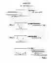
Lastly, there is a natural hydraulic limit that restricts well lengths and/or well diameters and can override pressure targets for SAGD operations. FIG. 9 (Prior Art) shows what can and has happened. In SAGD, a steam/liquids interface 12 is formed. For a good SAGD operation, with sub-cool control, the steam/liquids interface 12 is between the injector well 2 and producer well 4. The steam/liquids interface 12 is tilted because of the pressure drop in the producer well 4 due to frictional loses in fluid flow. There is little/no pressure differential in the steam/gas chamber. If the liquid production rates are too high (or if the producer well is too small) the interface 12 can be tilted so that the toe of the steam injector well 14 is flooded and/or the heel of the producer well 16 is exposed to steam breakthrough (FIG. 9). This limitation may occur when the pressure drop in the producer well 4 exceeds the hydrostatic head between the steam injector well 2 and liquids producer well 4 (about 8 psi (50 kPa) for a 5 metre spacing).
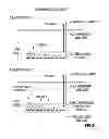
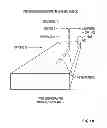
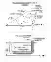
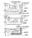
Steam-Assisted Gravity Drainage with Oxygen (“SAGDOX”) is an improved thermal EOR process where steam and oxygen are both injected into a bitumen reservoir. As best seen in FIG. 10, SAGDOX uses a horizontal production well 4 similar to SAGD and the addition of oxygen injection 26 via a variety of vertical or horizontal well configurations to inject steam 6 and oxygen 26 and remove non-condensable combustion gases 22 (i.e. vent gases) (FIGS. 10(a), 11(a), 11(b) and 12). FIG. 11(a) depicts a single production well where bitumen and water 8 are recovered through perforations 19 and non-condensable gas 22 is vented via a separate annulus. Oxygen 26 and steam 6 are injected in the pay zone 5 via a separate vertical well. FIG. 11(b) depicts a single production well where: oxygen 26 and steam 6 are injected into the pay zone 5, non-condensable gas 22 is vented via a separate annulus and bitumen and water 8 are recovered within the same well, all being segregated from each other. FIG. 12 depicts three preferred geometries. The SAGDOX process can be considered a hybrid SAGD and in situ combustion (“ISC”) process. Combustion, using oxygen, produces in situ heat that is less costly and more efficient than steam. Steam improves combustion kinetics, improves heat transfer and fosters lateral growth. Steam and oxygen injection rates and vent gas removal rates are adjusted to achieve target pressures. Production rates are controlled by sub-cool target temperatures similar to SAGD. Oxygen/steam ratios are adjusted within a range of 0.05 to 1.00 (v/v)), or in other words a steam to oxygen ratio of from 19 to 1.
The early versions of SAGDOX provide only for oxygen to steam ratios in the range of 0.05 to 1.00. There is a need to extend the oxygen to steam ratio beyond 0.05 to 1.00 and to determine optimal operating conditions in SAGDOX.
SUMMARY OF THE INVENTION
According to one aspect, there is provided a process to improve SAGDOX, said process comprising the use of produced-water-to-oil ratio (v/v) (“PWOR”) in determining optimal SAGDOX process parameters.
According to another aspect, there is provided the use of PWOR in controlling thermal EOR, preferably optimizing thermal EOR, more preferably optimizing SAGDOX in hydrocarbon recovery.
According to another aspect, there is provided an improved steam assisted gravity drainage with injected oxygen (“SAGDOX”) process to recover hydrocarbons comprising:
-
- (a) starting said SAGDOX process at a first oxygen to steam ratio;
- (b) measuring PWOR associated with said first oxygen to steam ratio;
- (c) adjusting said oxygen to steam ratio to a obtain a second PWOR;
- (d) measuring a hydrocarbon recovery rate associated with said second PWOR; and
- (e) repeating steps (c) and (d) until a PWOR target improving said hydrocarbon recovery rate is achieved.
In one embodiment, said improvement comprises extending the oxygen to steam ratios beyond the range of 0.05 to 1.00 (v/v), preferably a steam to oxygen ratio of from about 19 to approaching zero but greater than zero. In a preferred embodiment, the percent oxygen in said oxygen and steam mixture is greater than 50% (v/v).
Preferably, said PWOR target improving said hydrocarbon recovery is from about, 0.5 to 2.0, preferably 1.0. More preferably said PWOR target may be a maximum wherein said amount of oxygen in said process approaches zero but is greater than 0%.
In another embodiment, said improvement comprises using a PWOR to pick an optimal oxygen to steam ratio. In another embodiment, said improvement comprises adjusting pressure and sub-cool targets for optimizing SAGDOX. Preferably, the oxygen to steam ratio is adjusted to attain a target PWOR (Produced Water-to-Oil Ratio). In another embodiment a PWOR target is selected optimizing the oxygen to steam ratio in the SAGDOX process. In one embodiment, said oxygen injected is an oxygen containing gas.
According to one aspect, there is provided a process to recover liquid hydrocarbons from a hydrocarbon reservoir having a top and a bottom, using a substantially horizontal production well wherein:
-
- (1) said substantially horizontal production well produces water and liquid hydrocarbons from said reservoir; preferably said substantially horizontal production well is completed within 2 metres from the reservoir bottom;
- (2) oxygen is injected into the hydrocarbon reservoir, preferably above said substantially horizontal production well, preferably within 50 metres of the substantially horizontal production well; preferably said oxygen is injected by at least one oxygen injection well or site; said at least one oxygen injection well or site having at least one reservoir contact zone, for contacting said reservoir, said zone being preferably less than 50 metres in length;
- (3) steam is injected into the hydrocarbon reservoir, preferably above said substantially horizontal production well, preferably within 20 metres of the substantially horizontal production well; wherein
- (4) oxygen produces in situ heat by combustion and steam produces in situ heat by conduction and by condensation, causing the liquid hydrocarbon to be heated, lowering its viscosity so it drains by gravity to the horizontal production well through said at least one reservoir contact zone, said liquid hydrocarbon preferably being conveyed (more preferably pumped) to the surface;
- (5) oxygen to steam injected into said hydrocarbon reservoir is controlled to attain a target produced-water-to-oil ratio (v/v) (“PWOR”); preferably said oxygen to steam injected has a steam to oxygen ratio of from 19 to greater than zero;
- (6) non-condensable gases produced by combustion and inert gases in the oxygen containing gas (“vent gas”) are removed from the reservoir, preferably separate from said substantially horizontal production well via at least one vent gas site, more preferably from about 5 to about 75 metres from said substantially horizontal production well; and
- (7) more preferably said steam and oxygen are injected a predetermined distance from said at least one vent gas removal site, preferably at least 100 metres from said at least one vent gas removal site.
Preferably the PWOR target is between 0.5 and greater such that said amount of oxygen in said process approaches zero but is greater than zero, more preferably between 0.5 and about 2.0.
Preferably the PWOR target is determined, in the field, by changing PWOR until the cost, preferably opex cost, per bbl. bitumen, is minimized.
Optionally, according to one embodiment, it is not necessary to remove non-condensable combustion gases or inert gas components of the oxygen-containing gas.
Preferably, steam is injected within 10 metres from the horizontal well, more preferably using a parallel, horizontal well, in the same vertical plane as the horizontal production well and from 3 to 8 metres above the well.
In another embodiment, steam is injected into the reservoir using at least one single substantially vertical well, preferably a plurality of substantially vertical wells.
In another embodiment, oxygen, preferably oxygen-containing gas, is injected into the reservoir using at least one single substantially vertical well, preferably a plurality of substantially vertical wells.
In yet another embodiment, vent gas is removed from the reservoir using at least one single substantially vertical well, preferably a plurality of substantially vertical wells.
In yet another embodiment said steam and oxygen are comingled on the surface and injected into the reservoir using at least one single substantially vertical well, preferably a plurality of substantially vertical wells.
In yet another embodiment, said steam and oxygen are segregated using packers in at least one single substantially vertical well, preferably a plurality of substantially vertical wells, and injected separately into the reservoir.
According to another embodiment, said steam and oxygen are segregated using concentric tubing and packers in said well, preferably with steam in a central tubing surrounded by oxygen in an adjacent annulus, preferably said oxygen being injected at a higher elevation in the reservoir than said steam.
According to another embodiment, said process uses a single substantially vertical well to inject steam and oxygen, wherein the single substantially vertical well is completed within 50 metres from the toe of the horizontal production well.
According to another embodiment, said vent gas is removed using one well, preferably a substantially vertical well. In another embodiment said vent gas is removed using multiple vertical wells.
Preferably said vent gas is removed via a segregated annulus section in the heel rise section of the horizontal well.
In another embodiment, oxygen is injected into said reservoir through a segregated toe section of the horizontal well.
In another embodiment, steam is injected into said reservoir through a segregated toe section of the horizontal well.
In another embodiment, said steam and oxygen are comingled at the surface and injected into the reservoir through a segregated toe section of the horizontal well.
In another embodiment, said oxygen and steam are segregated and simultaneously injected into the reservoir through a segregated toe section of the horizontal well.
In another embodiment, said segregation is accomplished using concentric tubing and packers, with steam in the central tubing surrounded by oxygen in the adjacent annulus.
In another embodiment, said vent gas is removed in a segregated annulus in the heel rise section of the horizontal well.
In another embodiment, said toe of the horizontal well is drilled upwards and completed so the lowest injection orifice (for steam or oxygen-containing gas or both) is higher in elevation than the horizontal plane of the horizontal section of the production well, preferably greater than 2 metres higher in elevation than the horizontal plane of the horizontal section of the production well.
In another embodiment, the horizontal well is drilled substantially parallel to the reservoir bottom, in an up-dip direction in a slanted reservoir, so that the lowest injection orifice is higher in elevation than the highest liquid production well orifice, more preferably more than 2 metres higher in elevation than the highest liquid production orifice.
In another embodiment, the oxygen-containing gas is oxygen, with an oxygen content of 95 to 99.99 (v/v) percent.
In another embodiment, the oxygen-containing gas is air, preferably enriched air, with an oxygen content of 21 to 95 (v/v) percent.
In another embodiment, the process further comprises an extender tube proximate the toe of the production well is used, ensuring that the lowest pressure in the production well is proximate the toe.
When the hydrocarbon liquid is bitumen, preferably the API density is less than 10 and the in situ viscosity is greater than 100,000 cp. When the hydrocarbon liquid is heavy oil, preferably the API density is between 10 and 20 and the in situ viscosity is greater than 1,000 cp.
In one embodiment, the horizontal production well is less than 2.0 m from the bottom of the reservoir at its closest point.
Preferably the PWOR target is determined by changing PWOR until bitumen productivity is maximized.
BRIEF DESCRIPTION OF THE FIGURES
FIG. 1 depicts a traditional SAGD Geometry.
FIG. 2 depicts the SAGD Life Cycle.
FIG. 3 depicts saturated steam properties.
FIG. 4 depicts Residual bitumen in steam swept zones.
FIG. 5 depicts viscosity versus temperature of bitumen.
FIG. 6 depicts the Gravdrain equation for SAGD bitumen productivity.
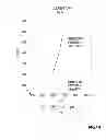
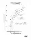
FIG. 7 depicts the transition SAGDOX to ISC.
FIG. 8 depicts SOR for Steam EOR at various Initial Oil Saturation levels.
FIG. 9 depicts SAGD Hydraulic limitations during good and poor operation conditions.
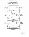
FIG. 10 depicts a preferred embodiment SAGDOX geometry with vent gas sites separate from the injector and producer wells.
FIG. 10a depicts a preferred embodiment SAGDOX geometry with a vent gas site proximate the producer well.
FIG. 11a depicts a preferred embodiment toe-to-heel SAGDOX geometry with oxygen and steam injected proximate the toe of the producer well.
FIG. 11b depicts a preferred embodiment single well SAGDOX with an uplifted toe geometry.
FIG. 12 depicts three preferred embodiments of SAGDOX geometry.
FIG. 13 depicts the combustion heat release HHV versus H/C atomic ratio of fuel.
FIG. 14 depicts pressure versus temperature of saturated steam.
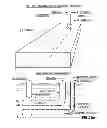
FIG. 15 depicts the SAGDOX Mechanisms in relation to hydrocarbon recovery.
FIG. 15(a) depicts the side view recovery pattern of THSAGDOX.
FIG. 16 depicts the required minimum air flux rates versus crude oil gravity for combustion.
FIG. 17 depicts Steam and Oxygen Combustion Tube Tests I.
FIG. 18 depicts Steam and Oxygen Combustion Tube Tests II.
FIG. 19 depicts SAGDOX Combustion Chemistry.
FIG. 20 depicts SAGDOX Combustion Component PWOR versus Initial Bitumen Saturation.
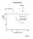
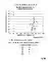
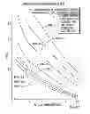
FIG. 21 depicts PWOR versus Initial Bitumen Saturation (at energy to oil ratio (“ETOR”)=1.0).
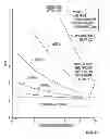
FIG. 22 depicts PWOR versus ETOR assuming Sio of 0.80.
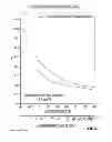
FIG. 23 depicts Combustion component PWOR at SAGDOX end-of-life.
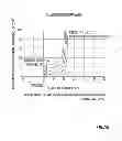
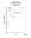
FIG. 24 depicts Tapered Oxygen Strategy as ETOR rises or SAGDOX matures.
FIG. 25 depicts WRR versus Initial Bitumen Saturation at various Oxygen concentrations.
FIG. 26 depicts % oil/bitumen recovery in steam-swept zones versus initial oil/bitumen saturation.
DETAILED DESCRIPTION OF THE INVENTION
The objective of SAGDOX is to reduce reservoir energy injection costs, while maintaining good efficiency and productivity. Oxygen combustion produces in situ heat at a rate of about 480 BTU/SCF oxygen, independent of fuel combusted (FIG. 13, Butler (1991)). Combustion temperatures are independent of pressure and they are higher than saturated steam temperatures (FIGS. 3, 14). The higher temperature from combustion vaporizes connate water and refluxes some steam. Steam delivers EOR energy from latent heat released by condensation with a net value, including surface heat recovery of about 1000 BTU/lb (FIG. 3). Table 1 presents thermal properties of steam+oxygen mixtures. Per unit heat delivered to the reservoir, oxygen volumes are ten times less than steam and oxygen costs (including capital charges) are one half to one third the cost of steam.
The recovery mechanisms are more complex for SAGDOX than for SAGD. As best seen in FIG. 15, the combustion swept zone 170 is contained within the steam-swept zone 170. Residual bitumen, in the steam-swept zone 120, is heated, fractionated and pyrolyzed by hot combustion gases to provide coke that is the actual fuel for combustion. A gas chamber is formed containing steam combustion gases, vapourized connate water, and other gases. The large gas chamber can be subdivided into a combustion-swept zone 100, a combustion front zone 110, a pyrolysis zone 120, a hot bitumen bank 130, a superheated steam zone 140, and a saturated steam zone 150. Condensed steam drains from the saturated steam zone 150 and from the ceiling and walls of the gas chamber. Hot bitumen drains from the ceiling and walls of the chamber and from the hot bitumen zone at the edge of the combustion front zone 110. Condensed water and hot bitumen 8 are collected by the lower horizontal well 4 and conveyed (or pumped) to the surface (FIG. 10). FIG. 15(a) depicts how the combustion swept zone grows during a SAGDOX process.
Combustion non-condensable gases are collected and removed by vent gas wells or at segregated vent gas sites (FIGS. 10, 10(a), 11(a) and 11(b) respectively). In one embodiment, process pressures may be partially controlled by vent gas production, independent of liquid production rates. Vent gas production may also be used to influence direction and rate of gas chamber growth.
Some SAGDOX Properties Include:
-
- (1) Use Oxygen (rather than air) as the oxidant injected.
- If the cost of treating vent gas to remove sulphur components and to recover volatile hydrocarbons is considered, even at low pressures, the all-in cost of oxygen is less than the cost of compressed air, per unit energy delivered to the reservoir.
- Oxygen occupies about one fifth the volume compared to air for the same energy delivery. Well pipes/tubing are smaller and oxygen can be transported further distances from a central plant site.
- In situ combustion using oxygen produces mostly non-condensable CO2, undiluted with nitrogen. CO2 can dissolve in bitumen to improve productivity. Dissolution is maximized using oxygen.
- Vent gas, using oxygen, is mostly CO2 and may be sequestered at as separate site or in a separate horizon.
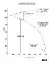
- There is a minimum oxygen flux to sustain high temperature oxidation (“HTO”) combustion (FIG. 16). FIG. 16 shows air flux rates. Oxygen rates are about 1/5 air flux rates. As burning zone thickness increases, the minimum ISC air flux rate decreases.
- It is easier to attain/sustain this flux using oxygen.
- (2) Keep oxygen injection at a concentrated site.
- Because of the minimum O2 flux constraint from in situ combustion (FIG. 16), the oxygen injection well (or a segregated section) should have no more than 50 metres of contact with the reservoir.
- (3) Segregate oxygen and steam injectants, as much as possible.
- Condensed steam (hot water) and oxygen are very corrosive to carbon steel.
- To minimize corrosion, either: (i) oxygen and steam are injected separately (FIGS. 10, 11(a)) or (ii) comingled steam and oxygen have limited exposure to a section of pipe that can be a corrosion resistant alloy, or the section integrity exposed to the comingled steam and oxygen is not critical to the process (FIG. 11(b)), or the entire injection string is made of a corrosion resistant alloy.
- (4) The vent gas well (or site) is proximate the top of the reservoir, and far from, or distant the oxygen injection site.
- Because of steam movement and condensation, non-condensable gas concentrates near the top of the gas chamber.
- The vent gas well is distant the oxygen injector to allow time/space for combustion and heat transfer.
- (5) Vent gas should not be produced with significant oxygen content.
- To mitigate explosions and to foster good oxygen utilization, any vent gas production with oxygen content greater than 5% (v/v) should be shut in.
- (6) Attain/retain a minimum amount of steam in the reservoir.
- Steam is added/injected with oxygen in SAGDOX because steam helps combustion. Steam preheats the reservoir so ignition, for HTO, can be spontaneous. Steam adds OH− and H+ radicals into the combustion zone to improve and stabilize combustion (FIGS. 17 and 18) (personal communication). This is also confirmed by the operation of smokeless flares, where steam is added to improve combustion and reduce smoke (Stone, D. et al, “Flares”, Chapter seven, www.gasflare.org, June, 2012, Environmental Protection Agency (“EPA”) “Industrial Flares”, EPA.gov, June 2012) (Shore, D. “Making the Flare Safe”, J. Loss Prey. Proc. Ind., 9, 363, 1996). The process to gasify fuel also adds steam to the partial combustor to minimize soot production (Berkowitz, N., “Fossil Hydrocarbons”, Academic Press, 1997).
- Steam also condenses and produces water that covers the horizontal production well and isolates it from gas or steam intrusion.
- Steam condensate adds water to the production well to possibly improve flow performance—water/bitumen emulsions—compared to bitumen alone.
- Steam is also a superior heat transfer agent in the reservoir. If you compare hot combustion gases (mostly CO2) to steam, the heat transfer advantages of steam are evident. For example, if we have a hot gas chamber at about 200° C. at the edges, the heat available from cooling combustion gases from 500° C. to 200° C. is about 16 BTU/SCF. The same volume of saturated steam contains 39 BTU/SCF of latent heat—more than twice the energy content of combustion gases. In addition, when hot combustion gases cool they become effective insulators, impeding further heat transfer. When steam condenses to deliver latent heat, it creates a transient low-pressure that draws in more steam comparable to a heat pump. The kinetics also favour steam/water. The heat conductivity of combustion gas is about 0.31 (mW/cmK) compared to the heat conductivity of water which is about 6.8 (mW/cmK)—an increase by a factor of 20. As a result, combustion (without steam) has issues of slow heat transfer and poor lateral growth. These issues may be mitigated by steam injection.
- Since we can't measure the amount of steam in the reservoir, SAGDOX sets a steam minimum by a maximum oxygen/steam (v/v) ratio of 1.0 or alternately 50% (v/v) oxygen in the steam and oxygen mix.
- (7) Attain (or exceed) a minimum oxygen_injection
- Below about 5% (v/v) oxygen in the steam and oxygen mix, the combustion swept zone is small and the cost advantages of oxygen are minimal. At this level, only about a third of the energy injected is due to combustion.
- (8) Maximum oxygen injection
- Within the constraints of (6) and (7) above, because per unit energy oxygen is less costly than steam, the lowest-cost option to produce bitumen is to maximize oxygen/steam ratios.
- (9) Use preferred SAGDOX geometries
- Depending on the individual application, reservoir matrix properties, reservoir fluid properties, depth, net pay, pressure and location factors, there are three preferred geometrics for SAGDOX (FIG. 12).
- Options B—Toe-to-Heel SAGDOX (“THSAGDOX”) and C—Single Well SAGDOX (“SWSAGDOX”) are best suited to thinner pay resources, with only one horizontal well required. Compared to SAGD, THSAGDOX and SWSAGDOX have a reduced well count and lower drilling costs. Also, internal tubulars and packers should be usable for multiple applications.
- (10) Control/operate SAGDOX by:
- Sub-cool control on fluid production rates where produced fluid temperature is compared to saturated steam temperature at reservoir pressure. This assumes that gases, immediately above the liquid/gas interface, are predominantly steam.
- Adjust oxygen/steam ratios (v/v) to meet a target ratio, subject to a range limit of 0.05 to 1.00
- Adjust vent gas removal rates so that the gases are predominantly non-condensable gases, oxygen content is less than 5.0% (v/v), and to attain/maintain pressure targets.
- Adjust steam and oxygen injection rates (subject to (ii) above), along with (iii) above, to attain/maintain pressure targets.
- (1) Use Oxygen (rather than air) as the oxidant injected.
The Improved SAGDOX Process
One of the suggested controls for original SAGDOX was to pick a target steam/oxygen mixture for injection. But, other than a suggested range of 5 to 50% (v/v) of oxygen in the mixture (or an oxygen to steam ratio of from 0.05 to 1.00), there were no guidelines on what or how to pick the best composition. The SAGDOXO (SAGDOX—optimized) process overcomes this deficiency. There are two considerations to picking a target composition—
(1) oxygen is less costly and more efficient than steam. So, oxygen levels should be maximized, based on these criteria, alone.
(2) Steam is very useful in the reservoir recovery process. In addition to providing latent heat to bitumen, it preheats zones for combustion, it is a better heat transfer medium than hot combustion gases, and water from steam, when mixed with produced bitumen, creates emulsions (or mixtures) that are easier to produce than bitumen by itself. There is an optimum level of steam in the reservoir that captures most of these benefits and allows oxygen levels to be increased as much as practical.
The key for the SAGDOXO process is to find an optimal level of steam and/or to identify a measurement related to steam performance that will allow steam level optimization by field adjustments, while maintaining other SAGDOX operation controls discussed herein. There is provided a process to optimize steam levels in SAGDOX, said process comprising selecting a PWOR target, preferably between 0.5 and greater such that the level of oxygen approaches zero but remains greater than zero, more preferably between 0.5 and 2.0, most preferably about 1.0, which minimizes bitumen cost.
In one embodiment, said PWOR target is selected which maximizes bitumen productivity.
PWOR (produced fluids, water-to-oil ratio) is also used as a measure to select the optimal oxygen to steam ratio. PWOR is not very useful for SAGD because it is usually close to SOR and normally, there is no reservoir water source that can affect PWOR and act as a performance measure for the SAGD process. In SAGD, based on field experience, connate water is not produced. For SAGDOX, the steam component behaves like SAGD. But the combustion component vapourizes and produces connate water so that PWOR>SOR. At steady state, PWOR for SAGDOX is a direct measure of steam injected and steam produced per unit bitumen production.
According to one aspect, there is provided an optimized SAGDOX process (SAGDOXO) comprising the following 3 components:
-
- (1) identification of a measure, preferably PWOR, that can be used as directly related to steam/bitumen ratios in the reservoir,
- (2) a PWOR target between 0.5 and a maximum such that the level of oxygen approaches zero but remains greater than 0, more preferably between 0.5 and 2.0, most preferably 1.0 for operation of SAGDOX, in a new reservoir,
- (3) a method to find the optimum PWOR and oxygen/steam mixture for a specific reservoir, by varying the PWOR target (and oxygen/steam mix) to either minimize bitumen costs at reasonable productivity or to maximize bitumen productivity; and
- (4) a steam to oxygen ratio of from 19 to approaching zero, but greater than zero.
Examples
In analyzing the PWOR-target implications and mechanics of the SAGDOXO process, the following assumptions are made:
(1) SAGDOX is broken into 2 component processes—steam EOR operates like SAGD, with heat delivered by steam condensation and hot bitumen drainage by gravity; and combustion EOR heats bitumen, directly and indirectly by oxidation of residual bitumen components.
(2) Steam EOR assumes the following:
-
- Steam energy delivers about 1000 BTU/lb. steam, net (FIG. 3).
- All steam injected is produced as water.
- The steam swept zone 170, in SAGDOX, precedes the combustion zone (FIG. 15), with residual bitumen in the zone providing the fuel precursor for combustion.
- All connate water, in the (saturated) steam-swept zone remains in the reservoir, consistent with SAGD field experience.
(3) Combustion EOR component, assumes the following: - Combustion energy is delivered at 480 BTU/SCF oxygen (FIG. 13).
- The fuel combusted is coke, with a simplified formula of CH5 (FIG. 13), prepared by the fractionation and pyrolysis of residual bitumen in the steam-swept zone 170 (FIG. 15).
- Complete HTO is assumed. FIG. 19 provides SAGDOX combustion chemistry.
- All water produced as a chemical product of combustion, is produced.
- Residual bitumen and connate water in the combustion—swept zone is zero (FIG. 15). The zone is occupied by gases.
- All connate water associated with bitumen produced and consumed to combustion is produced.
(4) For purposes of PWOR assessment, SAGDOX is considered a linear combination of combustion and steam EOR, with the following assumptions: - Bitumen produced by each component is prorated by energy delivered.
- The energy delivered is at the sand face (sf).
- For steam, there is a 10% heat loss between the well head (wh) and the sand face. The condensed steam, due to this heat loss, drains to the production well and adds to produced water volumes.
- There is no initial gas saturation in the pay zone.
As a result of the above process model, we can assess the results and impacts of the process with a focus on PWOR, as follows:
PWOR is evaluated for bitumen saturations of 0.6 to 1.0; percent oxygen, in steam+oxygen mixes, from greater than 0 to less than 100 (v/v) % (preferred range is 5 to 50%); and ETOR (MMBTU/bbl bitumen (“bblB”)) from 1.0 to 2.0 (equivalent to SOR from 3 to 6) for a mature operation.
A PWOR of 1.0 or greater may result in good (SAGDOXO) operation, with maximum oxygen content and good heat transfer and other benefits due to steam (i.e. preferred value for target PWOR). But, each reservoir (or recovery pattern) can be different due to geological or fluid property variations. A SAGDOXO operator can start with a PWOR=1 and adjust PWOR to account for specific reservoir conditions. The operational history of nearby or similar reservoirs may also be used to adjust targets.
There are 2 ways to ‘optimize’ PWOR targets using field results. First, PWOR can be used to minimize bitumen costs, while maintaining ‘reasonable’ bitumen productivity. Second, PWOR can be adjusted to maximize bitumen productivity.
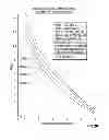
FIG. 20 shows, based on the above assumptions, the PWOR performance is almost independent of ETOR for the combustion component of SAGDOX. This is because the water produced as a product of combustion and the connate water associated with bitumen combusted are small compared to connate water associated with bitumen produced.
FIG. 20 also shows why dry ISC is not a good option for bitumen EOR. If the threshold for good heat transfer (and other steam benefits) is PWOR=1.0, dry ISC will not work well (i.e. productivity) unless the initial bitumen saturation is ≦0.5, independent of ETOR.
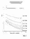
Consider a bitumen reservoir with a typical bitumen saturation of 0.8, our mature SAGDOXO process operates with ETOR=1.0 (equivalent to SOR˜3 for SAGD), and the PWOR target is 1.0 (i.e. the produced fluids are 50% water and 50% bitumen). FIG. 21 shows that the SAGDOXO process should be operated with a steam+oxygen mixture containing about 25% (v/v) oxygen, or equivalently, with an oxygen/steam ratio (v/v) 0.33. For this target PWOR, this maximizes oxygen content, in this reservoir.
The above example can also be used to verify (and specify) the range limitations of SAGDOXO (between 5 and 50 (v/v) % oxygen in the steam+oxygen mixture). Suppose our ETOR=1.0 MMBTU/bblB for a mature project (a SAGD equivalent of SOR of about 3); our initial bitumen saturation ranges from 0.75 to 0.90; and our PWOR target range is 0.75 to 1.50. Then, FIG. 21 shows that the oxygen content in the oxygen/steam mixture should vary from about 10 to 50 percent—consistent with the SAGD range limits.
Although the above ranges justify the limits for SAGDOX gases (5 to 50 (v/v)) % oxygen in the oxygen+steam mixture, SAGDOXO strategy extends oxygen levels outside the original SAGDOX limits. As the SAGDOXO process matures, ETOR will increase, as heat losses increase, and the SAGDOXO process strategy dictates an increase in oxygen levels. For example, using FIG. 22, for Sio=0.8 and PWOR=1.0, at prime maturity with ETOR=1.0, the suggested oxygen level is about 25% oxygen in the oxygen-steam mixture. If the ETOR climbs to 2.0 (equivalent to SOR˜6), the suggested oxygen level is in excess of 50% in the oxygen-steam mixture, namely 60% O2—beyond the traditional SAGDOX target range.
(9) A SAGDOX operating strategy for this invention, is to taper the oxygen levels in the steam+oxygen mix, starting at a low oxygen level and eventually, near the end-of-life (FIG. 2) injecting only oxygen without steam. This is intuitive, since oxygen is less costly than steam. The SAGDOXO process automatically captures this strategy. Near the end-of-life, the surface area exposed to non-productive zones can be high and the drainage angle is small (FIG. 2). ETOR can climb until the economic limits are reached. For oxygen alone, ETOR as high as about 16 is feasible. As ETOR increases the water/steam production of the combustion component increases due to more water of combustion produced and more connate water (related to bitumen combusted) produced. FIG. 23 shows PWOR for combustion-only for elevated ETOR performance. For initial bitumen situations≦0.9, as ETOR climbs above 10, it is not necessary to inject any steam (i.e. steam is 0%), if the threshold for good (steam) heat transfer is PWOR≧1.0. If we relax our performance criteria, for an end-of-life SAGDOXO project to PWOR>0.5, as long as ETOR≧4, we need not inject any steam for Sio<0.9. The prospect of using only oxygen (i.e. steam=0%, oxygen=100%), near the end-of-life SAGDOXO project, ensures minimization of operating costs (since oxygen is less costly, per unit energy, than steam) and the maximization of ultimate recovery (i.e. reserves).
(10) FIG. 24 shows how oxygen levels, in injectant gases, rises as ETOR increases, for a specific case (Sio=0.8, PWOR target=1.0). Above an ETOR=8.0, it is not necessary to inject steam. The injectant gas is oxygen, alone. There is enough steam produced in the reservoir, to attain PWOR=1.0 targets, by using connate water vapourized by heat and steam produced directly by combustion.
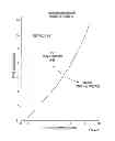
(11) FIG. 7 shows the transition points, from steam+oxygen (SAGDOX) to oxygen-alone (ISC), as a function of ETOR and initial bitumen saturations, assuming a PWOR=1.0 target. For bitumen saturations less than about 0.5, there is enough connate water vapourized plus water of combustion, to meet PWOR targets, for all ETOR values, without any steam injection.
(12) The SAGDOXO process, using the PWOR target system, is also useful if the process encounters a lean zone, with low bitumen saturation (<0.6) and high connate water saturation (>0.4). As combustion encounters the lean zone, water is produced and PWOR increases (temporarily). The SAGDOXO remedy is to increase oxygen content of the feed gas (steam+oxygen). This reduces operating costs and maintains PWOR targets. When the zone is breached, the oxygen levels are reduced.
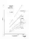
(13) FIG. 25 and Table 5 show the impact of SAGDOX and SAGDOXO on water-recycle ratios (produced water/injected steam). Assuming produced-water-treatment yields of 90%, if WRR exceeds 1.1, no make-up water is needed. As long as oxygen levels, in injected gases, exceed about 10%, the process produces more water than necessary to sustain steam production without any make-up or fresh water needed.
Some Distinctions Between SAGDOXO and SAGDOX are:
-
- SAGDOX includes a range of preferred oxygen concentration (5 to 50% in steam+oxygen mixes); SAGDOXO extends the range (unlimited).
- SAGDOX suggest the operator can pick an oxygen/steam mix; SAGDOXO provides a method to optimize the oxygen/steam ratio.
- SAGDOXO uses PWOR as a target measure to optimize performance; SAGDOX has no such measure.
- SAGDOXO automatically develops a strategy to taper steam injection as the project matures; SAGDOX has no such preference.
- SAGDOX always injects a steam+oxygen mixture; SAGDOXO can convert to a ISC process for high ETOR operation or for lean bitumen reservoirs.
Some Unique Features of SAGDOXO Include:
-
- target, measure (PWOR) to optimize oxygen/steam mixture composition.
- automatic tapering (lowering steam injection, increasing oxygen) as process ages and ETOR increases.
- consideration of bitumen saturation as a key factor to control and optimize process.
- automatic response to lean zone encounters in reservoir (lower steam levels until zone is breached).
- no fixed range of oxygen/steam ratios; no limits.
- suggested initial target of PWOR≧1.0.
| TABLE 1 |
| SAGDOX: Injection Gas Properties |
| % (v/v) | % heat | BTU/SCF | MSCF |
| O2 in mix | from O2 | from steam | mix | mix/MMBTU |
| 0 | 0 | 100.00 | 47.37 | 21.11 |
| 5 | 34.76 | 65.23 | 69.03 | 14.49 |
| 10 | 52.95 | 47.05 | 90.66 | 11.03 |
| 20 | 71.68 | 28.32 | 133.92 | 7.47 |
| 30 | 81.27 | 18.73 | 177.18 | 5.64 |
| 40 | 87.10 | 12.90 | 220.44 | 4.54 |
| 50 | 91.01 | 8.99 | 263.70 | 3.79 |
| 60 | 93.82 | 6.18 | 306.96 | 3.26 |
| 70 | 95.94 | 4.06 | 350.22 | 2.86 |
| 80 | 97.59 | 2.41 | 393.48 | 2.54 |
| 90 | 98.91 | 1.09 | 436.74 | 2.29 |
| 100 | 100.00 | 0.00 | 480.00 | 2.08 |
| Where | ||||
| mix = steam + oxygen | ||||
| steam at 1000 BTU/lb. | ||||
| oxygen at 480 BTU/SCF |
| TABLE 2 |
| SAGDOX Combustion Component PWOR |
| (Mature Process) |
| Initial Bitumen Saturation |
| .5 | .6 | .7 | .8 | .9 | |
| ETOR = 1.0 | ||||||
| 1 | 1.00 | 0.67 | 0.43 | 0.25 | 0.11 | |
| 2 | 0.17 | 0.08 | 0.07 | 0.04 | 0.02 | |
| 3 | 0.06 | 0.06 | 0.06 | 0.06 | 0.06 | |
| PWOR | 1.23 | 0.81 | 0.56 | 0.35 | 0.19 | |
| ETOR = 1.5 | ||||||
| 1 | 1.00 | 0.67 | 0.43 | 0.25 | 0.11 | |
| 2 | 0.26 | 0.12 | 0.11 | 0.06 | 0.03 | |
| 3 | 0.08 | 0.08 | 0.08 | 0.08 | 0.08 | |
| PWOR | 1.34 | 0.87 | 0.62 | 0.41 | 0.23 | |
| ETOR = 2.0 | ||||||
| 1 | 1.00 | 0.67 | 0.43 | 0.25 | 0.11 | |
| 2 | 0.34 | 0.17 | 0.14 | 0.08 | 0.04 | |
| 3 | 0.11 | 0.11 | 0.11 | 0.11 | 0.11 | |
| PWOR | 1.45 | 0.95 | 0.68 | 0.44 | 0.26 | |
| Where | ||||||
| entries are bblsW/bblB | ||||||
| 1 = connate water associated with produced bitumen | ||||||
| 2 = connate water associated with combusted bitumen fuel | ||||||
| 3 = water of combustion | ||||||
| PWOR = 1 + 2 + 3 | ||||||
| Water of combustion = 0.056 bbl/MBTU | ||||||
| Fuel combusted = coke (CH.5) |
| TABLE 3 |
| SAGDOX Steam Component |
| Water Balance |
| (bblW/bblB) | |
| ETOR (sf.) = 1.0 | ||
| SOR (sf) | 2.857 | |
| SOR (wh.) | 3.175 | |
| PWOR | 3.175 | |
| ETOR (sf.) = 1.5 | ||
| SOR (sf) | 4.286 | |
| SOR (wh.) | 4.762 | |
| PWOR | 4.762 | |
| ETOR (sf.) = 2.0 | ||
| SOR (sf) | 5.714 | |
| SOR (wh.) | 6.349 | |
| PWOR | 6.349 | |
| Where | ||
| wh = well head; sf = sand face | ||
| 10% heat loss wh to sf | ||
| all steam injected is produced | ||
| no connate water is produced | ||
| steam at 1000 BTU/lb;.35 MMBTU/bbl | ||
| bblW = bbl water; | ||
| bblB = bbl bitumen | ||
| PWOR = produced WOR |
| TABLE 4 |
| SAGDOX: PWOR (ETOR = 1.0) |
| Initial Bitumen Saturation |
| % O2 in mix (v/v) | .5 | .6 | .7 | .8 | .9 |
| 0 | PWOR (steam) | 3.18 | 3.18 | 3.18 | 3.18 | 3.18 |
| PWOR (O2) | 0 | 0 | 0 | 0 | 0 | |
| PWOR | 3.18 | 3.18 | 3.18 | 3.18 | 3.18 | |
| 10 | PWOR (steam) | 1.50 | 1.50 | 1.50 | 1.50 | 1.50 |
| PWOR (O2) | .65 | .43 | .30 | .19 | .10 | |
| PWOR | 2.15 | 1.93 | 1.80 | 1.69 | 1.60 | |
| 20 | PWOR (steam) | 0.90 | 0.90 | 0.90 | 0.90 | 0.90 |
| PWOR (O2) | .88 | .58 | .40 | .25 | .14 | |
| PWOR | 1.78 | 1.48 | 1.30 | 1.15 | 1.04 | |
| 40 | PWOR (steam) | 0.41 | 0.41 | 0.41 | 0.41 | 0.41 |
| PWOR (O2) | 1.07 | 0.71 | 0.49 | 0.30 | 0.17 | |
| PWOR | 1.48 | 1.12 | 0.90 | 0.71 | 0.58 | |
| 60 | PWOR (steam) | 0.20 | 0.20 | 0.20 | 0.20 | 0.20 |
| PWOR (O2) | 1.15 | 0.76 | 0.53 | 0.33 | 0.18 | |
| PWOR | 1.35 | 0.96 | 0.73 | 0.53 | 0.38 | |
| 80 | PWOR (steam) | 0.08 | 0.08 | 0.08 | 0.08 | 0.08 |
| PWOR (O2) | 1.20 | 0.79 | 0.55 | 0.34 | 0.19 | |
| PWOR | 1.28 | 0.87 | 0.63 | 0.42 | 0.27 | |
| 100 | PWOR (steam) | 0 | 0 | 0 | 0 | 0 |
| PWOR (O2) | 1.23 | 0.81 | 0.56 | 0.35 | 0.19 | |
| PWOR | 1.23 | 0.81 | 0.56 | 0.35 | 0.19 | |
| Where | ||||||
| PWOR = bbls water/bbl B | ||||||
| PWOR = includes PWOR (O2) Table 2 + PWOR (steam) Table 3 prorated by energy supplied | ||||||
| All for ETOR total = 1MMBTU/bblB |
| TABLE 5 |
| SAGDOX: WRR (Water Recycle Ratios) |
| (ETOR = 1.0) |
| % | Injected | Initial Bitumen Saturation |
| O2 in mix | steam (bbl) | .5 | .6 | .7 | .8 | .9 |
| 0 | 3.18 | 1.00 | 1.00 | 1.00 | 1.00 | 1.00 |
| 10 | 1.50 | 1.43 | 1.29 | 1.20 | 1.13 | 1.07 |
| 20 | 0.90 | 1.98 | 1.64 | 1.44 | 1.28 | 1.16 |
| 40 | 0.41 | 3.61 | 2.73 | 2.20 | 1.73 | 1.41 |
| 60 | 0.20 | 6.75 | 4.80 | 3.65 | 2.65 | 1.90 |
| 80 | 0.08 | 16.00 | 10.88 | 7.88 | 5.25 | 3.38 |
| Where: | ||||||
| entries are WRR(v/v) = water produced/steam injected | ||||||
| ETOR = 1MMBTU/bbl B | ||||||
| See Tables 4.3 |
| TABLE 6 |
| SAGDOX Combustion Component PWOR |
| (End of Life) |
| Initial Bitumen Saturation |
| ETOR | .5 | .6 | .7 | .8 | .9 | |
| 1.0 | 1.23 | .81 | .56 | .35 | .19 | |
| 2.0 | 1.45 | .95 | .68 | .44 | .26 | |
| 4.0 | 1.90 | 1.22 | .94 | .64 | .41 | |
| 8.0 | 2.81 | 1.78 | 1.46 | 1.04 | .71 | |
| 12.0 | 3.71 | 2.34 | 1.96 | 1.42 | 1.00 | |
| 16.0 | 4.62 | 2.90 | 2.48 | 1.82 | 1.31 | |
| Where | ||||||
| entries are PWOR = bbls water/bbl bitumen | ||||||
| PWOR includes water associated with produced bitumen + water | ||||||
| Water of combustion = .0562 bbl/MMBTU | ||||||
| ETOR for combustion component MMTBU/bbl | ||||||
| Fuel = coke (CH.5)(FIG. 18) | ||||||
| O2 heat at 480 BTU/SCF | ||||||
| Bit fuel value = 6 MMBTU/bblB |
As many changes therefore may be made to the embodiments of the invention without departing from the scope thereof. It is considered that all matter contained herein be considered illustrative of the invention and not in a limiting sense.
Claims
1. The use of produced-water-to-oil ratio (v/v) (“PWOR”) in thermal enhanced oil recovery (“EOR”), for controlling said thermal EOR.
2. The use of claim 1 wherein PWOR is used in optimizing said thermal EOR.
3. A steam assisted gravity drainage with injected oxygen (SAGDOX) process to recover hydrocarbons in a hydrocarbon reservoir comprising:
(a) starting said SAGDOX process at a first oxygen to steam ratio;
(b) measuring a produced water to oil ratio (v/v) PWOR associated with said first oxygen to steam ratio;
(c) adjusting said oxygen to steam ratio to obtain a predetermined PWOR; and
(d) continuing steps (a) to (c) until a target PWOR is obtained improving said hydrocarbon recovery rate.
4. A steam assisted gravity drainage with injected oxygen (“SAGDOX”) process to recover hydrocarbons, wherein said SAGDOX process has a steam to oxygen ratio of from about 19 to greater than zero.
5. A steam assisted gravity drainage with injected oxygen process (“SAGDOX”) to recover hydrocarbons, wherein said SAGDOX has a oxygen to steam ratio determined by a produced water to oil ratio (“PWOR”).
6. The process of claim 3 wherein said PWOR is between about 0.5 and greater to a maximum such that the amount of oxygen approaches zero but is greater than zero.
7. The process of claim 6 wherein said PWOR is between about 0.5 and 2.00, and said oxygen to steam ratio is from about 0% to 100% oxygen to steam.
8. The process of claim 6 wherein said PWOR is 1.0.
9. The process of claim 3 wherein the oxygen has an oxygen content of 95 to 99.99 (v/v) percent.
10. The process of claim 8 wherein the oxygen is enriched air, with an oxygen content of 21 to 95 (v/v) percent.
11. A process according to claim 1 wherein the hydrocarbon in said hydrocarbon reservoir to be recovered is bitumen with an API density of less than 10 and an in situ viscosity greater than 100,000 cp.
12. A process according to claim 1 wherein the hydrocarbon in said hydrocarbon reservoir to be recovered is heavy oil with an API density between 10 and 20 and an in situ viscosity greater than 1,000 cp.
13. The use according to claim 1, 2 or 3 where a PWOR target is determined by changing said PWOR until bitumen productivity is maximized.
Images & Drawings included:


Sources:
- United States Patent and Trademark Office - verify current appl. status at the USPTO↗
Recent applications in this class:
- » 20250027395 2025-01-23
LATE LIFE STEAM DRIVE AND GAS STRATEGY - » 20240263550 2024-08-08
METHODS FOR REPURPOSING THERMAL HYDROCARBON RECOVERY OPERATIONS FOR SYNTHESIS GAS PRODUCTION - » 20240183257 2024-06-06
Continuous chamber capillary control system, method, and apparatus - » 20240003234 2024-01-04
MODULES AND CONFIGURATIONS OF MODULES FOR HYDROCARBON WELLS - » 20230392486 2023-12-07
Method, apparatus, real time modeling and control system, for steam and steam with super-heat for enhanced oil and gas recovery - » 20230147037 2023-05-11
Method, apparatus, and system for enhanced oil and gas recovery with super focused heat - » 20230083972 2023-03-16
Method and system for downhole steam generation using laser energy - » 20230045845 2023-02-16
Steam-enhanced hydrocarbon recovery using hydrogen sulfide-sorbent particles to reduce hydrogen sulfide production from a subterranean reservoir - » 20220364446 2022-11-17
Laser gravity heating - » 20220349288 2022-11-03
Method and system for downhole steam generation using laser energy
Recent applications for this Assignee:
- » 20180306693 2018-10-25
Emulsion composition sensor - » 20140166279 2014-06-19
EXTENDED REACH STEAM ASSISTED GRAVITY DRAINAGE WITH OXYGEN ("ERSAGDOX") - » 20140166278 2014-06-19
USE OF STEAM-ASSISTED GRAVITY DRAINAGE WITH OXYGEN ("SAGDOX") IN THE RECOVERY OF BITUMEN IN LEAN ZONES ("LZ-SAGDOX") - » 20140144623 2014-05-29
METHOD FOR INCREASING PRODUCT RECOVERY IN FRACTURES PROXIMATE FRACTURE TREATED WELLBORES - » 20140138287 2014-05-22
Integrated central processing facility (CPF) in oil field upgrading (OFU) - » 20140096962 2014-04-10
STEAM ASSISTED GRAVITY DRAINAGE WITH ADDED OXYGEN ("SAGDOX") IN DEEP RESERVOIRS - » 20140096960 2014-04-10
USE OF STEAM ASSISTED GRAVITY DRAINAGE WITH OXYGEN ("SAGDOX") IN THE RECOVERY OF BITUMEN IN THIN PAY ZONES