Securing and supporting apparatus for mobile electronic devices
US20140076745A1
2014-03-20
14/020,912
2013-09-09
✅ Patent granted
US 8,931,745 B2
2015-01-13
-
-
Todd M Epps
Ella Cheong Hong Kong | Sam T. Yip
2033-09-09
Abstract:
An apparatus for securing and supporting a mobile electronic device, comprising a protective shell for mounting the mobile electronic device, the protective shell comprising a female connector, wherein the female connector having a first magnet; and a support for fixing to a supporting surface, the support comprising a male connector, wherein the male connector having a second magnet; wherein the protective shell and the support constitute a detachable connecting structure; and wherein exposed ends of the first magnet and the second magnet having opposite magnetic poles. When joining the protective shell and the support, the male and female connectors need only be placed in approximate of each other for the connectors to be drawn towards each other and guided into proper alignment by magnetic force exerted by the two magnets. This way, the user's sight on the joining process is not necessary.
Assignee:
- INNOMAX LIMITED 1 🇭🇰 Hong Kong, Hong Kong
- Innomax Limited 1 🇭🇰 Kowloon, Hong Kong, Hong Kong
Applicant:
Interested in similar patents?
Get notified when new applications in this technology area are published.
Classification:
A45C11/00 » CPC main
Receptacles for purposes not provided for in groups -
F16B2001/0035 » CPC further
Devices for securing together, or preventing relative movement between, constructional elements or machine parts by the use of a magnetic material
G06F1/1613 » CPC further
Details not covered by groups - and; Constructional details or arrangements for portable computers
B60R11/0252 » CPC further
Arrangements for holding or mounting articles, not otherwise provided for for radio sets, television sets, telephones, or the like; Arrangement of controls thereof for personal computers, e.g. laptops, notebooks
H04M1/04 » CPC further
Substation equipment, e.g. for use by subscribers; Constructional features of telephone sets Supports for telephone transmitters or receivers
G06F1/16 IPC
Details not covered by groups - and Constructional details or arrangements
F16B1/00 IPC
Devices for securing together, or preventing relative movement between, constructional elements or machine parts
A45C2011/002 » CPC further
Receptacles for purposes not provided for in groups - for portable handheld communication devices, e.g. mobile phone, pager, beeper, PDA, smart phone
A47G1/17 IPC
Mirrors ; Picture frames or the like, e.g. provided with heating, lighting or ventilating means; Devices for hanging or supporting pictures, mirrors, or the like using adhesives, suction or magnetism
A45C13/18 » CPC further
Details; Accessories Devices to prevent theft or loss of luggage or bags
H04B1/3888 » CPC further
Details of transmission systems, not covered by a single one of groups - ; Details of transmission systems not characterised by the medium used for transmission; Transceivers, i.e. devices in which transmitter and receiver form a structural unit and in which at least one part is used for functions of transmitting and receiving; Portable transceivers Arrangements for carrying or protecting transceivers
B60R11/02 IPC
Arrangements for holding or mounting articles, not otherwise provided for for radio sets, television sets, telephones, or the like; Arrangement of controls thereof
H04B1/38 IPC
Details of transmission systems, not covered by a single one of groups - ; Details of transmission systems not characterised by the medium used for transmission Transceivers, i.e. devices in which transmitter and receiver form a structural unit and in which at least one part is used for functions of transmitting and receiving
Description
CLAIM FOR FOREIGN PRIORITY
This application claims priority under 35 U.S.C. §119 to the China Utility Model Patent Application No. 201220477217.8, filed Sep. 19, 2012, the disclosure of which is incorporated herein by reference in its entirety.
COPYRIGHT NOTICE
A portion of the disclosure of this patent document contains material, which is subject to copyright protection. The copyright owner has no objection to the facsimile reproduction by anyone of the patent document or the patent disclosure, as it appears in the Patent and Trademark Office patent file or records, but otherwise reserves all copyright rights whatsoever.
FIELD OF THE INVENTION
The presently claimed invention relates generally to apparatuses used in securing and supporting mobile electronic devices on to persons or articles.
BACKGROUND
To secure a mobile electronic device, such as a mobile phone, tablet, laptop computer, or navigator, inside an automobile and water vessel passenger compartment, on motorcycle, bicycle, or a person's body, etc. for ease of use, a supporting and securing structure is generally necessary for attaching the device on to some fixture.
A common mobile electronic device supporting and securing accessory can comprise a protective shell for mounting the mobile electronic device and a support fixed to a supporting surface, wherein the protective shell and the support constitute a detachable connecting structure. The protective shell is provided with a female connector while the support is provided with a male connector. The protective shell and the support are connected together by their respective connectors, the device is secured within the protective shell, the support is fixed on to the supporting surface, and ultimately the mobile electronic device is secured for use.
The entire installation process is simple. However, if the mobile electronic device is large in size or that the user's line of sight is obscured, it is difficult to align the protective shell and the support's connectors to join them together, resulting in difficult fitting and installation.
SUMMARY
It is the objective of the presently claimed invention to overcome the shortcoming of the prior art; that is, the difficulty in joining the mobile electronic device in its protective shell to the support in providing the securing and supporting structure for the mobile electronic device.
It is the objective of the presently claimed invention to provide an apparatus for securing and supporting mobile electronic devices. In one embodiment, the securing and supporting apparatus comprising a protective shell for mounting a mobile electronic device and a support fixed to the supporting surface, wherein the protective shell and the support constitute a detachable connecting structure. The protective shell is provided with a female connector. The female connector is provided with a slot and a fastening end for connecting a male connector. The support is provided with a male connector, the male connecter is provided a fastener. For connecting the male and female connectors, the male connector is inserted into the slot and connected with the female connector in a sliding manner, then the fastener of the male connector is fastened to the fastening end of the female connector, as such the male connector is connected to the female connector.
In accordance to one embodiment, the interior of the male connector is installed a permanent magnet having a convex shape, and the interior of the female connector is installed another permanent magnet having a concave shape. The magnetic poles of the exposed ends of the two magnets are of opposite of each other, so that when the male connector is inserted into the slot of the female connector, the female connector magnet attracts the male connector magnet. The magnets are used for aiding the alignment of the male and female connectors while the male connector is being inserted into the slot of the female connector. When joining the protective shell and the support, the male and female connectors need only be placed in approximate of each other for the connectors to be drawn towards each other and guided into proper alignment by magnetic force exerted by the two magnets. This way, the user's sight on the joining process is not necessary.
BRIEF DESCRIPTION OF THE DRAWINGS
Embodiments of the invention are described in more detail hereinafter with reference to the drawings, in which:
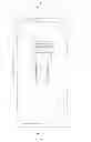
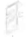
FIG. 1 is a schematic structural view of one embodiment of the presently claimed invention;
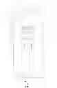
FIG. 2 is an A-A sectional view of FIG. 1;
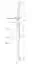
FIG. 3 is a schematic structural view of one embodiment of the presently claimed invention under an unlocked state; and
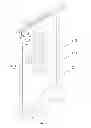
FIG. 4 is a perspective view of one embodiment of the presently claimed invention under an unlocked state.
DETAILED DESCRIPTION
In the following description, designs of apparatuses for securing and supporting mobile electronic devices are set forth as preferred examples. It will be apparent to those skilled in the art that modifications, including additions and/or substitutions may be made without departing from the scope and spirit of the invention. Specific details may be omitted so as not to obscure the invention; however, the disclosure is written to enable one skilled in the art to practice the teachings herein without undue experimentation.
In the drawings, the number labels' definitions are: 1—male connector, 1-1—fastener, 2—female connector, 2-1—fastening end, 2-2—slot, and 3—protective shell.
As shown in the drawings, in accordance to one embodiment of the presently claimed invention, a mobile electronic device securing and supporting apparatus comprises a protective shell 3 for mounting the mobile electronic device and a support fixed to the supporting surface. The protective shell 3 and the support constitute a detachable connecting structure. The protective shell 3 is provided with a female connector 2. The female connector 2 is provided with a slot 2-2 and a fastening end 2-1 for connecting a male connector 1. The support is provided with a male connector 1. The size of the insertion end of the male connector 1 corresponds to the size of the slot 2-2. The male connecter 1 is provided a fastener 1-1. For connecting the male and female connectors, the male connector 1 is inserted into the slot 2-2 and connected with the female connector 2 in a sliding manner, then the fastener 1-1 of the male connector 1 is fastened to the fastening end 2-1 of the female connector 2, as such the male connector 1 is connected to the female connector 2.
In accordance to one embodiment of the presently claimed invention, the interior of the male connector 1 is provided with an opening for installing magnet, in which a permanent magnet having a convex shape is installed. The interior of the female connector 2 is provided with another opening for installing magnet, in which a permanent magnet having a concave shape is installed. The magnetic poles of the exposed ends of the two magnets are of opposite of each other, and the sizes and placements of the two magnets correspond each other, so that when the male connector is inserted into the slot of the female connector, the female connector magnet attracts the male connector magnet.
To better guide the insertion of the male connector 1 into the slot 2-2 of the female connector 2, the preferred placements of the male connector magnet and the female connector magnet in this embodiment are as such: when the male connector magnet attracts the female connector magnet for connection, the male connector 1 is located at the starting end of the slot 2-2 of the female connector 2.
In actual use, firstly, the male connector 1 is brought in proximity with the female connector 2, allowing the male connector magnet and the female connector magnet to attract each other. The magnetic force exerted by the magnets guide the male connector 1 to align with the female connector 2 for inserting into the starting end of the slot 2-2 of the female connector 2, and draw the male connector 1 to slide into the inner side of the female connector 2 along the slot 2-2. Finally, the fastener 1-1 of the male connector 1 is fastened to the fastening end 2-1 of the female connector 2, and the male connector 1 and the female connector 2 are locked together. The male connector 1 and the female connector 2 are connected and secured together, the mobile electronic is embedded in the protective shell 3, the support is fixed to the supporting surface, and ultimately the mobile electronic device is properly secured and supported for use.
To detach the support from the protective shell, firstly loosen the fastener 1-1 of the male connector 1. Secondly, slide the male connector 1 outward away from the female connector 2. The male connector magnet is attracted to the female connector magnet such that to guide the male connector 1 to return to the starting end of the slot 2-2 of the female connector 2. Finally, the user pulls the male connector 1 out from the female connector 2 to complete the detachment. This way, the user's sight on the protective shell-support joining and detachment processes is not necessary.
The foregoing description of the present invention has been provided for the purposes of illustration and description. It is not intended to be exhaustive or to limit the invention to the precise forms disclosed. Many modifications and variations will be apparent to the practitioner skilled in the art.
The embodiments were chosen and described in order to best explain the principles of the invention and its practical application, thereby enabling others skilled in the art to understand the invention for various embodiments and with various modifications that are suited to the particular use contemplated. It is intended that the scope of the invention be defined by the following claims and their equivalence.
Claims
What is claimed is:1. An apparatus for securing and supporting a mobile electronic device, comprising:
a protective shell for mounting the mobile electronic device, the protective shell comprising a first connector, wherein the first connector having a first magnet; and
a support for fixing to a supporting surface, the support comprising a second connector, wherein the second connector having a second magnet;
wherein the protective shell and the support constitute a detachable connecting structure; and
wherein exposed ends of the first magnet and the second magnet having opposite magnetic poles.
2. The apparatus of claim 1,
wherein the first connector being a female connector and further comprising a slot and a fastening end; and
wherein the second connector being a male connector and further comprising a fastener;
such that when connecting the first and second connectors, the second connector is inserted into the slot of the first connector in a sliding manner, then the fastener of the second connector is fastened to the fastening end of the first connector.
3. The apparatus of claim 1,
wherein the first magnet having a concave shape; and
wherein the second magnet having a convex shape.
Images & Drawings included:
Sources:
- United States Patent and Trademark Office - verify current appl. status at the USPTO↗
Recent applications in this class:
- » 20250280935 2025-09-11
SECURITY BAG AND METHOD OF USE - » 20250255390 2025-08-14
PROTECTIVE ANTENNA PACKAGE AND TRANSPORT UNIT THEREFOR - » 20250234971 2025-07-24
CASE FOR A PERSONAL ELECTRONIC DEVICE - » 20250234970 2025-07-24
CASE FOR A PERSONAL ELECTRONIC DEVICE - » 20250213016 2025-07-03
PROTECTIVE CASE FOR MOBILE DEVICE AND MOBILE DEVICE WITH THE PROTECTIVE CASE - » 20250204660 2025-06-26
UNIVERSAL DEVICE HOLDER - » 20250204659 2025-06-26
ELECTRONIC DEVICE PROTECTIVE COVER - » 20250204658 2025-06-26
VR silicone integrated handle protective casing - » 20250143427 2025-05-08
DEPLOYABLE SUPPORT APPARATUS - » 20250134226 2025-05-01
ELECTRONIC DEVICE PROTECTIVE COVER