Free breeze accelerator
US20140097639A1
2014-04-10
14/048,024
2013-10-07
✅ Patent granted
US 8,910,994 B2
2014-12-16
-
-
Lori L Lyjak
Coastal Patent Law Group, P.C. | Joshua S. Schoonover
2033-10-07
Abstract:
One embodiment comprised of two long triangular shaped bodies, one larger in width than the other to facilitate an insertion that is telescopic and covered at opposing ends by end caps, one smaller than the other to communicate with each of the said bodies width. The center of each end cap comprising of a triangular shaped sleeve and a retaining hole to secure the end of each triangular body; both said end caps positioned with the back mounting side in the same direction, thus perpendicular to each other so that the mounting holes can face an exterior surface. In addition, the said embodiment is made with resilient material such as polyvinyl chloride (PVC) to support UV protection and weather resistance.
Applicant:
Interested in similar patents?
Get notified when new applications in this technology area are published.
Classification:
B62D35/008 » CPC main
Vehicle bodies characterised by streamlining Side spoilers
B62D35/00 » CPC further
Vehicle bodies characterised by streamlining
B60J9/04 IPC
Devices not provided for in one of main groups - Air curtains
Description
REFERENCE TO RELATED APPLICATIONS
This application claims the benefit of provisional patent application Ser. No. 61/711.748 filed Oct. 10, 2012 by the present inventor.
BACKGROUND OF THE INVENTION
The present embodiment relates to a wind diverter device that is mounted on an exterior surface in front of an opening to the interior structure, such as a window, for the purpose of capturing and redirecting wind in a lateral bi-directional manner into the interior of the structure.
BACKGROUND PRIOR-ART
The following is a tabulation of some prior art that presently appears relevant.
| U.S. Patents |
| Pat. No. | Issue Date | Patantee. |
| U.S. Pat. No. 6,669,270 | Dec. 30, 2003 | Card, Loyd Ray, |
| Card Helen Joyce | ||
| US D683678 | May 08, 2004 | Weakes, Jeffrey, Jacobs, |
| Edward S. | ||
| U.S. Pat. No. 4,316,630 A | Feb. 23, 1982 | Evans, Jack L. |
| U.S. Pat. No. 4,141,580 | Feb. 27, 1979 | Ivan, Joseph R |
Previously, a device or apparatus with the capability to deflect or re-direct air has been manufactured having a rectangular, curved, angled, wedged or a right triangular form which is mounted on a given structure such as the top of a semi-truck, the rear cab of a pickup truck, or in front of a ceiling air vent. In U.S. Pat. No. D68367S to Weakes and Jacobs, air vent deflectors are designated for use with an air vent in a suspended ceiling grid of an interior structure with the purpose of redirecting forced air flow down and away from air vents to reduce the amount of debris accumulating on the grid and ceiling tiles. The air deflector prevents air vents from blowing in one direction by using metal foils. In reference to air deflectors stated for use in the automotive industry as in U.S. Pat. No. 4,316,630 to Evans, and U.S. Pat. No. 4,141,560 to Ivan, such air deflectors have proven to reduce wind displacement; eliminate drag, increase fuel mileage, and reduce the amount of road debris. Whereby, the air flow moves over an angled shield like design and away from a semi-truck or trailer while in transit. In addition, an air deflector that is vertically mounted, proposed by U.S. Pat. No. 6,669,270 to Card and Card, also considered an air foil, embodies two long hollow wedge type forms that are mounted perpendicular at the rear cab of a pickup truck, thus affecting the air flow away from the vehicle.
Although the above mentioned air deflectors all redirect air flow away from the vent or vehicle, the present wind device, has the advantage of capturing and redirecting wind with the purpose of increasing ventilation into an interior structure. While patent U.S. Pat. No. 6,669,270, to Card and Card also proposes mounting their embodiment vertically, the present proposed embodiment is enclosed by end caps instead of remaining hollow, mounts at the end of each end cap instead of mounting flat, and is telescopic to allow adjustment in a variety of structural frames whereas Card and Card's air deflector is non-adjustable. While the previous mentioned inventions are suitable for their intended applications, none are intended to capture and re-direct air into an interior structure using only natural wind as confirmed by The San Diego Low Speed Wind Tunnel, Test No. 1235.
SUMMARY
In accordance with one embodiment wind is captured and redirected bilaterally into an open structure by means of a curved telescopic triangular embodiment. The upper larger triangular body is of slightly larger width, thus overlapping on top of the lower smaller triangular body and held into place. In addition, the embodiment is comprised of two end caps, one also of slightly larger width man the other, and inserted according to width into the opposing end of the main body, by use of a triangular sleeve and secured by retaining screws. Prior to installation, the said body is placed in a vertical position, whereby it is adjusted and then mounted to the flat mounting side of each said end cap using either an independent bonding agent or by the use of independent screws, which can be inserted into two parallel holes that exist on the flat side of each said end cap.
ADVANTAGES
Accordingly, several advantages exist in the function of the embodiment and are as follows:
- (a) Wind flow is captured and re-directed in a bilateral manner without use of electricity using only nature's power to increase ventilation into an open structure.
- (b) The said embodiment is lightweight and can be easily adjusted to different lengths to fit various exterior frames by means of an expansion that is telescopic and adjusted by manual operation.
- (c) The embodiment can be made using polyvinyl chloride (PVC) in order to withstand wind speeds of over 40 mph, tested and demonstrated effective at the San Diego Low Speed Wind Tunnel as documented in Test Data 1235.
- (d) The use of such materials as polyvinyl chloride (PVC) offer the advantage of UV protection, and weather resistance.
- (e) The said embodiment can be extruded using recyclable materials such as polyvinyl chloride (PVC), thereby qualifying for status as a green product.
- (g) The embodiment can be manufactured with the option of using a variety of colors as well as pigments that are water based, thus less toxic to the environment
- (h) The embodiment can be extruded in several different lengths and widths to accommodate a variety of structures.
- (i) The option of attaching the end caps to various exterior structures by means of bonding agent allows the option to vertically mount the said embodiment without drilling.
- (j) The assembled embodiment resists the infestation of vermin, bees and other insects by securing each component so that no holes or gaps exist.
- (k) Once mounted, the said embodiment itself requires no further operation.
- (l) The said embodiment functions using silent operation.
- (m) The said embodiment has the ability to be detached manually from the exterior surface and then relocated to an alternate location.
DRAWINGS—FIGURES
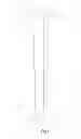
FIG. 1 is the embodiment as it is shown assembled.
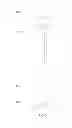
FIG. 2 is the exploded perspective of the embodiment.
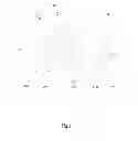
FIG. 3 is the larger top end cap from a perspective view prior to insertion displaying various aspects of the said end cap with reinforcement braces, an inner triangular shaped sleeve, and a retaining screw hole to be attached with the retaining screw in accordance with one embodiment.
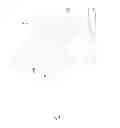
FIG. 4 is the smaller bottom end cap from a perspective view prior to insertion displaying various aspects of the said end cap with reinforcement braces, an inner triangular shaped sleeve, and a retaining screw hole to be attached with the retaining screw in accordance with one embodiment.
DRAWINGS—REFERENCE NUMERALS
- 10 larger top end cap
- 12 upper larger triangular body
- 14 lower smaller triangular body
- 16 smaller bottom end cap
- 18 A retaining screw hole for top larger end cap
- 18 B retaining screw hole for smaller bottom end cap
- 20 A retaining screw hole for upper larger triangular body
- 20 B retaining screw hole for lower smaller triangular body
- 22 A retaining screw hole in smaller bottom end cap sleeve
- 24 A reinforcement braces for larger top end cap
- 24 B reinforcement braces for smaller bottom end cap
- 26 A mounting hole in larger top end cap
- 26 B mounting hole in larger top end cap
- 28 A mounting hole in smaller bottom end cap
- 28 B mounting hole in smaller bottom end cap
- 30 A larger top end cap sleeve
- 30 B smaller bottom end cap sleeve
DETAILED DESCRIPTION
Referring now to FIG. 1, the wind diverter device is in complete assembled form, prior to vertical installation, wherein the larger upper triangular body 12 overlaps the smaller lower triangular body 14 with the larger top end cap 10, the smaller bottom end cap 16 positioned accordingly to their opposing ends of the main body and each secured by a retaining screw 18 A and 18 B, the opposing end caps being perpendicular.
Referring now to FIG. 2, the wind diverter device is seen from an exploded view prior to assembly and prior to installation with each component; upper larger triangular body 12, lower smaller triangular body 14, the smaller bottom end cap 16, larger top end cap 10, and retaining screws 18 A, 18 B directly adjacent to their coordinating hole, the larger upper triangular body 12 will be slightly larger than the lower smaller triangular body 14 in order to communicate with the slightly larger opening. In accordance, the sleeve of smaller bottom end cap 30 B will be of slightly smaller width than the larger end cap sleeve 30 A to communicate with said body openings 12, 14.
Referring now to FIG. 3, the larger top end cap 10 is seen from a perspective view with the center triangular sleeve 30 A facing downward, the retaining screw hole 22 A from an exterior view, the reinforcement braces 24 A facing downward, and the two parallel mounting holes 26 A, 26 B also seen from a downward interior position.
Referring now to FIG. 4, the smaller end cap is seen from perspective view, facing upward, the retaining screw hole 22 B is seen from an exterior view, the reinforcement braces 24 B also facing upward and the two parallel mounting holes 28 A, 28 B seen from an upward exterior position. Accordingly, the width of the smaller bottom end cap sleeve 30 B being slightly smaller in order to facilitate a connection to a slightly smaller width opening of the smaller lower body.
Operation—FIG. 1, 2, 3, 4
The method of assembling the embodiment consists of inserting each of the four parts into their corresponding component. Namely, one first attaches the larger top end cap 10 into the opening of the upper larger triangular body 12; the sleeve of said end cap 22 A inserts into the center of said opening and is thus secured with a screw through a retaining screw hole 18 A. Wherein the said upper larger triangular body 12 and the larger top end cap 10 are attached, one then follows the same procedure for the lower smaller triangular body 14 and its corresponding smaller bottom end cap 16, the smaller bottom end cap sleeve 30 B and retaining screw hole 22 B, secured by retaining screw 18 A. With each of the said end caps secured to their corresponding body, one then holds each body so that the mounting side of both end caps are aligned in the same direction, thus being perpendicular. One then inserts the smaller lower body 14 into the opening of the upper larger triangular body 12.
As shown in FIG. 1, the embodiment, when fully assembled, is thereby ready to be mounted or adhered vertically to an exterior structure in front of an open structure such as a window. Mounting can then be accomplished by using independent screws (not shown) when placed though each of the parallel mounting holes of the smaller bottom end cap 28A and 28B or by use of an independent bonding agent (not shown). Once the upper larger triangular body 10 is in position and secured to the outside of the upper frame of the exterior surface, one then uses the telescopic means of lengthening or shortening the two bodies so that the smaller bottom and lower smaller end cap are positioned directly outside of the frame of the opening structure; whereby two screws (not shown) can be inserted into the two parallel holes of the smaller bottom end cap 28 A and 28 B, then the larger top end cap 26 A and 26 B. Thereby, when the interior structure such as a window is opened, wind can be captured both bilaterally by the embodiment and redirected into the said open structure.
CONCLUSION, RAMIFICATIONS, AND SCOPE
Accordingly, the reader will see that the wind diverter device when vertically mounted can capture and redirect the wind bilaterally into an open interior structure using silent operation
without the use of electricity.
-
- allows the use of recyclable materials, but is not limited to the use of recyclable materials;
- allows the use of polyvinyl chloride (PVC) to provide UV protection, and is weather resistant but is not limited to the use of such materials
- allows extrusions of the said embodiment to be produced in several different lengths and widths to adjust to a variety of exterior structures without altering the operation of the said embodiment;
- allows vertical attachment of the embodiment using an independent bonding agent or by use of independent screws but is not limited to the use of such materials;
- allows extrusions of the said embodiment to be made in several different lengths and widths using the same operation and is not limited to the extrusion of a specific measurement of length or width;
- permits use in a variety of exterior structures and exterior surfaces including motor homes, manufactured homes, residential, institutional and commercial structures, but is not limited to the use in motor homes, manufactured homes, residential or commercial structures;
- permits use on the exterior of motor homes and manufactured homes while in transit.
While the above description contains many specifications, these should not be construed as limitations on the scope of any embodiment, but as exemplifications of various embodiments thereof. Many other ramifications and variations are possible within the teachings of various embodiments. For example, the end caps may consist of other shapes such as oval, the main body can be adjusted with a fastener or a notch, the end cap holes may be eliminated and replaced with an attached hinge, and the embodiment can be extruded from materials other than polyvinyl chloride (PVC) or plastic.
Thus the scope should be determined by the appended claims and their legal equivalents and not by the examples given.
Claims
1. A vertically expandable bilateral wind diverter device formed of resilient weatherproof material to be used on the exterior surface of a potentially open interior structure comprising of two long main bodies, both triangular in shape, each with retaining screw holes, one of smaller width to fit into the body of larger width, thus overlapping, the larger body in an upper position, the lower body in a lower position to permit manual lengthening and shortening, thus being telescopic; two opposing end caps each with reinforced braces, an inner triangular sleeve, and a retaining screw hole; one said end cap slightly larger in size and the other end cap slightly smaller in size, thus connecting to opposing ends in accordance to size and held into place on each opposing body by use of retaining screws; whereby said embodiment is vertically positioned to an exterior structural opening, thereby mounted by independent screws, the said end caps having two holes for said screws, or adhered by the use of an independent bonding agent.
Images & Drawings included:

Sources:
- United States Patent and Trademark Office - verify current appl. status at the USPTO↗
Recent applications in this class:
- » 20250263138 2025-08-21
WIND NOISE REDUCTION GARNISH - » 20250256789 2025-08-14
PLENUM SKIRTING FOR POWERED DOWNFORCE - » 20250249968 2025-08-07
AERODYNAMIC SYSTEM AND ADJUSTABLE FAIRINGS - » 20250128773 2025-04-24
AIRFLOW DEFLECTOR FOR VEHICLE SENSOR - » 20250033715 2025-01-30
AIR DOOR ADJUSTABLE AIR DEFLECTOR FOR OPEN AIR DRIVING APPLICATIONS - » 20240359754 2024-10-31
Side Wind Protector - » 20240359753 2024-10-31
DOOR MIRROR STRUCTURE - » 20240343322 2024-10-17
AIR-GUIDING ELEMENT AND MOTOR VEHICLE COMPRISING AN AIR-GUIDING ELEMENT - » 20240343321 2024-10-17
ADJUSTABLE MOTOR VEHICLE LATERAL AIR DEFLECTOR ARRANGEMENT - » 20240010283 2024-01-11
Exterior Trim for a Motor Vehicle