Endoscope objective optical system
US20140098429A1
2014-04-10
14/050,796
2013-10-10
✅ Patent granted
US 8,786,955 B2
2014-07-22
-
-
David N Spector
Kenyon & Kenyon LLP
2033-10-10
Abstract:
The diameter of an endoscope insertion portion is reduced, and a wide field angle of an endoscope insertion portion is obtained. An endoscope objective optical system includes, from an object side, a first lens formed of a plano-concave lens having a concave surface facing an image side, a second lens formed of a plano-concave lens having a concave surface facing the object side, an aperture stop, and a third lens formed of a plano-convex lens having a plane surface facing the object side, and satisfies
0.7≦|fab/f|0.9
1.7≦|fe/fab|≦2
2≦fb/fa≦4
where f: focal length of the entire system; fa: focal length of the first lens; fb: focal length of the second lens; fe: represents focal length of the third lens; fab: combined focal length from the first lens to the second lens.
Assignee:
- OLYMPUS MEDICAL SYSTEMS CORP. 1,821 🇯🇵 Tokyo, Japan
Applicant:
Interested in similar patents?
Get notified when new applications in this technology area are published.
Classification:
G02B9/12 » CPC main
Optical objectives characterised both by the number of the components and their arrangements according to their sign, i.e. + or - having three components only
A61B1/00 » CPC further
Instruments for performing medical examinations of the interior of cavities or tubes of the body by visual or photographical inspection, e.g. endoscopes ; Illuminating arrangements therefor
A61B1/00 » CPC further
Diagnosis; Psycho-physical tests
A61B1/00163 » CPC further
Instruments for performing medical examinations of the interior of cavities or tubes of the body by visual or photographical inspection, e.g. endoscopes ; Illuminating arrangements therefor Optical arrangements
G02B23/243 » CPC main
Telescopes, e.g. binoculars; Periscopes; Instruments for viewing the inside of hollow bodies; Viewfinders; Optical aiming or sighting devices; Instruments or systems for viewing the inside of hollow bodies, e.g. fibrescopes; Optical details of the distal end Objectives for endoscopes
G02B23/26 IPC
Telescopes, e.g. binoculars; Periscopes; Instruments for viewing the inside of hollow bodies; Viewfinders; Optical aiming or sighting devices; Instruments or systems for viewing the inside of hollow bodies, e.g. fibrescopes using light guides
A61B1/051 » CPC further
Instruments for performing medical examinations of the interior of cavities or tubes of the body by visual or photographical inspection, e.g. endoscopes ; Illuminating arrangements therefor combined with photographic or television appliances characterised by the image sensor, e.g. camera, being in the distal end portion Details of CCD assembly
G02B13/04 IPC
Optical objectives specially designed for the purposes specified below Reversed telephoto objectives
G02B23/24 IPC
Telescopes, e.g. binoculars; Periscopes; Instruments for viewing the inside of hollow bodies; Viewfinders; Optical aiming or sighting devices Instruments or systems for viewing the inside of hollow bodies, e.g. fibrescopes
A61B1/05 IPC
Instruments for performing medical examinations of the interior of cavities or tubes of the body by visual or photographical inspection, e.g. endoscopes ; Illuminating arrangements therefor combined with photographic or television appliances characterised by the image sensor, e.g. camera, being in the distal end portion
Description
TECHNICAL FIELD
The present invention relates to an endoscope objective optical system.
BACKGROUND ART
Conventionally, in order to obtain a lens system suitable for use of a solid-state imaging element, it is known to use an objective optical system which has a long back focus and a small size and which provides improvements in optical performance, such as an improvement in color reproducibility and a satisfactory correction of the image field curvature (see, for example, PTL 1).
The objective optical system disclosed in PTL 1 is used for forming an object image on a solid-state imaging element arranged on a linear optical axis. Therefore, a prism, and the like, which bends the optical axis, does not need to be arranged between the objective optical system and the solid-state imaging element, and hence a certain length of back focus is sufficient for the formation of the object image.
CITATION LIST
Patent Literature
- {PTL 1} Japanese Unexamined Patent Application, Publication No. Hei 10-197787
SUMMARY OF INVENTION
Technical Problem
However, in an ultra-thin video-scope type endoscope (whose insertion portion has an outer diameter of, for example, 3 mm), it is dimensionally difficult that a substrate with a solid-state imaging element mounted thereon is arranged perpendicularly to the linearly extending optical axis of the objective optical system. Therefore, it is necessary that the substrate is arranged in parallel with the optical axis of the objective optical system, and that the optical axis is bent by a prism arranged between the objective optical system and the imaging element. When such configuration is adopted, a sufficiently long back focus is needed in order to arrange the prism between objective optical system and the imaging element. Therefore, such configuration is difficult to be realized by the objective optical system disclosed in PTL 1.
The present invention has been made in view of the above described circumstances. An object of the present invention is to provide an endoscope objective optical system capable of reducing the diameter of an endoscope insertion portion and obtaining a wide field angle of the endoscope insertion portion.
Solution to Problem
In order to achieve the above described object, the present invention provides the following solutions.
An aspect of the present invention provides an endoscope objective optical system including, in order from an object side, a first lens formed of a plano-concave lens having a concave surface facing an image side, a second lens formed of a plano-concave lens having a concave surface facing the object side, an aperture stop, and a third lens formed of a plano-convex lens having a plane surface facing the object side, the endoscope objective optical system satisfying the following conditional expressions (1) to (3):
0.7≦|fab/f|≦0.9 (1)
1.7≦|fe/fab|≦2 (2)
2≦fb/fa≦4 (3)
where f represents a focal length of the entire system, fa represents a focal length of the first lens, fb represents a focal length of the second lens, fe represents a focal length of the third lens, and fab represents a combined focal length from the first lens to the second lens.
According to the present aspect, when the endoscope objective optical system satisfies conditional expression (1), a long back focus can be obtained, and when the endoscope objective optical system satisfies conditional expression (2), a wide field angle can be obtained. Further, when the endoscope objective optical system satisfies conditional expression (3), the height of a light beam passing through the first lens can be suppressed low and thereby the diameter of the first lens can be reduced. That is, in the endoscope objective optical system which satisfies these three conditions (1) to (3), a long back focus can be obtained so that an imaging element can be arranged in parallel with the optical axis of the objective optical system and the optical axis can be bent by a prism. Also, the diameter of the endoscope objective optical system can be reduced so as to be applicable to an ultra-thin insertion portion, and the field angle of the endoscope objective optical system can be increased.
In the above-described aspect, the endoscope objective optical system may satisfy the following conditional expression (4):
0.9≦Na/Nb≦1 (4)
where Na represents a refractive index at a d-line of a glass material forming the first lens, and Nb represents a refractive index at a d-line of a glass material forming the second lens.
With this configuration, the curvature of the second lens can be made large, as a result which the total thickness of the second lens can be reduced. Therefore, the distance from the first lens to the brightness diaphragm can be reduced, so that the height of the light beam passing through the first lens can be suppressed low and thereby the diameter of the first lens can be further reduced.
Advantageous Effects of Invention
According to the present invention, it is possible to obtain the effects that the diameter of an endoscope insertion portion is reduced and that a wide field angle of the endoscope insertion portion is obtained.
{BRIEF DESCRIPTION OF DRAWINGS}
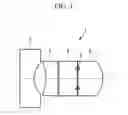
FIG. 1 is a view showing an endoscope objective optical system according to an embodiment of the present invention.
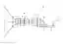
FIG. 2 is a view showing an imaging optical system including the endoscope objective optical system of FIG. 1.
FIG. 3 is a view showing a modification of the endoscope objective optical system of FIG. 1.
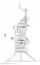
FIG. 4 is a view showing a lens array of an imaging optical system including a first example of the endoscope objective optical system of FIG. 1.
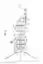
FIG. 5 is a view showing a lens array of an imaging optical system including a second example of the endoscope objective optical system of FIG. 1.
FIG. 6 is a view showing a lens array of an imaging optical system including a third example of the endoscope objective optical system of FIG. 1.
FIG. 7 is a view showing a lens array of an imaging optical system including a fourth example of the endoscope objective optical system of FIG. 1.
DESCRIPTION OF EMBODIMENT
In the following, an endoscope objective optical system 1 according to an embodiment of the present invention will be described with reference to the accompanying drawings.
As shown in FIG. 1, the endoscope objective optical system 1 according to the present embodiment includes, in order from the object side, a first lens 2, a second lens 3, an infrared cut filter 4, an aperture stop 5, and a third lens 6.
The first lens 2 is a plano-concave lens and is arranged so that the concave surface thereof faces the image side.
The second lens 3 is a plano-concave lens and is arranged so that the concave surface thereof faces the object side.
The third lens 6 is a plano-convex lens and is arranged so that the plane surface thereof faces the object side.
In the present embodiment, each of the lenses 2, 3 and 6 satisfy the following conditional expressions (1) to (4).
0.7≦|fab/f|≦0.9 (1)
1.7≦|fe/fab|≦2 (2)
2≦fb/fa≦4 (3)
0.9≦Na/Nb≦1 (4)
Here, f represents the focal length of the entire system, fa represents the focal length of the first lens 2, fb represents the focal length of the second lens 3, fe represents the focal length of the third lens 6, fab represents the combined focal length from the first lens 2 to the second lens 3, Na represents a refractive index at a d-line of a glass material forming the first lens 2, and Nb represents a refractive index at a d-line of a glass material forming the second lens 3.
The effects of the endoscope objective optical system 1 according to the present embodiment configured in this way are described as follows.
In the endoscope objective optical system 1 according to the present embodiment, each of the first lens 2 and the second lens 3 is configured by a plano-concave lens, so that the negative power can be divided by the two lenses 2 and 3. Therefore, the negative power of each of the first lens 2 and the second lens 3 can be made smaller than the negative power at the time when the portion corresponding to the first and second lenses 2 and 3 is realized by using a single lens. As a result, ease of processing can be improved as compared with the case where a lens having a small diameter and strong negative power is processed.
Further, when the endoscope objective optical system 1 according to the present embodiment satisfies conditional expression (1), a long back focus can be obtained.
That is, as shown in FIG. 2, the endoscope objective optical system 1 according to the present embodiment is used in such a manner that a substrate 7 is arranged in parallel with the optical axis of the endoscope objective optical system 1, and that a parallel plate 9 and a prism 10 are arranged between the endoscope objective optical system 1 and a solid-state imaging element 8 provided on the substrate 7.
The back focus length of the endoscope objective optical system 1 is increased to thereby enable the parallel plate 9 and the prism 10 to be arranged. Even with such arrangement, the size of the substrate 7 does not directly affect the size of the outer diameter of the insertion portion. Therefore, even when the size of the substrate 7 is large, the diameter of the insertion portion can be reduced. In FIG. 2, reference numeral 11 denotes a wiring connected to the substrate 7, and reference numeral 12 denotes an adhesive layer.
Further, when the endoscope objective optical system 1 according to the present embodiment satisfies conditional expression (2), a wide field angle can be obtained.
Further, when the endoscope objective optical system 1 according to the present embodiment satisfies conditional expression (3), the height of the light beam passing through the first lens 2 can be suppressed low. As a result, the outer diameter of the first lens 2 can be reduced, and thereby the outer diameter of the insertion portion can be reduced.
When the endoscope objective optical system 1 according to the present embodiment satisfies the above-described three conditions, the back focus can be made long enough to provide the prism 10, and the like. Therefore, the endoscope objective optical system 1 according to the present embodiment has advantages of reducing the diameter of the insertion portion and of increasing the field angle.
Further, when the endoscope objective optical system 1 according to the present embodiment satisfies conditional expression (4), the curvature of the second lens 3 can be kept large. As a result, the total thickness of the second lens 3 is made small, so that the distance from the first lens 2 to the brightness diaphragm 5 can be reduced. That is, the height of the light beam passing through the first lens 2 can be suppressed low also by this effect. As a result, the outer diameter of the first lens 2 can be made small, and thereby the diameter of the insertion portion can be further reduced.
It should be noted that, in the present embodiment, an example is shown in which the infrared cut filter 4 is arranged between the second lens 3 and the third lens 6, but instead of this arrangement, as shown in FIG. 3, the infrared cut filter 4 may be arranged between the first lens 2 and the second lens 3.
EXAMPLES
Next, examples of the endoscope objective optical system 1 according to the above-described embodiment will be described below.
First Example
FIG. 4 shows a lens array of an imaging optical system 20 including the endoscope objective optical system 1, according to a first example of the present embodiment, and Table 1 shows lens data. The lens data of Table 1 are normalized so that the focal length of the entire system is substantially equal to 1.
In the present example, the field angle is set to 108°.
| TABLE 1 | ||||
| Surface number | r | d | n | ν |
| Object | ∞ | 56.577 | ||
| 1 | ∞ | 0.6506309 | 1.7682 | 71.79 |
| 2 | 1.001406 | 0.4813701 | ||
| 3 | −2.944812 | 0.6223426 | 1.882997 | 40.765107 |
| 4 | ∞ | 0.057 | ||
| 5 | ∞ | 0.848649 | 1.52113 | 66.5 |
| 6 | ∞ | 0 | ||
| STO | ∞ | 0.0282883 | ||
| 8 | ∞ | 0 | ||
| 9 | ∞ | 1.131532 | 1.882997 | 40.765107 |
| 10 | −1.306919 | 0.7358551 | ||
| 11 | ∞ | 1.131532 | 1.51633 | 64.142022 |
| 12 | ∞ | 0.0565766 | 1.51 | 64.14 |
| 13 | ∞ | 2.480884 | 1.61061 | 50.2 |
| 14 | ∞ | 0 | ||
Further, in the present example, the specification values of the lenses are as follows.
fab=−0.849
f=0.988
fa=−3.335
fb=−1.304
fe=1.48
Na=1.7682
Nb=1.882997
Second Example
FIG. 5 shows a lens array of an imaging optical system 20 including the endoscope objective optical system 1, according to a second example of the present embodiment, and Table 2 shows lens data. The lens data of Table 2 are normalized so that the focal length of the entire system is substantially equal to 1.
In the present example, the field angle is set to 100°.
| TABLE 2 | ||||
| Surface number | r | d | n | ν |
| Object | ∞ | 53.855 | ||
| 1 | ∞ | 0.6193284 | 1.7682 | 71.79 |
| 2 | 0.9532272 | 0.373 | ||
| 3 | ∞ | 0.8078197 | 1.52113 | 66.5 |
| 4 | ∞ | 0.139 | ||
| 5 | −2.803134 | 0.5924011 | 1.882997 | 40.765107 |
| 6 | ∞ | 0 | ||
| STO | ∞ | 0.02692732 | ||
| 8 | ∞ | 0 | ||
| 9 | ∞ | 1.077093 | 1.882997 | 40.765107 |
| 10 | −1.14979 | 70.7054959 | ||
| 11 | ∞ | 1.077093 | 1.51633 | 64.142022 |
| 12 | ∞ | 0.05385465 | 1.51 | 64.14 |
| 13 | ∞ | 2.361526 | 1.61061 | 50.2 |
| 14 | ∞ | 0 | ||
Further, in the present example, the specification values of the lenses are as follows.
fab=−0.722
f=0.989
fa=−1.241
fb=−3.175
fe=1.302
Na=1.7682
Nb=1.882997
Third Example
FIG. 6 shows a lens array of an imaging optical system 20 including the endoscope objective optical system 1, according to a third example of the present embodiment, and Table 3 shows lens data. The lens data of Table 3 are normalized so that the focal length of the entire system is substantially equal to 1.
In the present example, the field angle is set to 125°.
| TABLE 3 | ||||
| Surface number | r | d | n | ν |
| Object | ∞ | 62.893 | ||
| 1 | ∞ | 0.7232704 | 1.882997 | 40.765107 |
| 2 | 1 | 0.4865849 | ||
| 3 | −4.207973 | 0.6918239 | 1.92286 | 18.896912 |
| 4 | ∞ | 0.06289308 | ||
| 5 | ∞ | 0.9433962 | 1.52113 | 66.5 |
| 6 | ∞ | 0 | ||
| STO | ∞ | 0.06289308 | ||
| 8 | ∞ | 0 | ||
| 9 | ∞ | 1.259103 | 1.882997 | 40.765107 |
| 10 | −1.43547 | 0.8115168 | ||
| 11 | ∞ | 1.257862 | 1.51633 | 64.142022 |
| 12 | ∞ | 0.06289308 | 1.51 | 64.14 |
| 13 | ∞ | 2.757862 | 1.61061 | 50.2 |
| 14 | ∞ | 0 | ||
Further, in the present example, the specification values of the lenses are as follows.
fab=−0.829
f=0.999
fa=−1.126
fb=−4.504
fe=1.616
Na=1.882997
Nb=1.92286
Fourth Example
FIG. 7 shows a lens array of an imaging optical system 20 including the endoscope objective optical system 1, according to a fourth example of the present embodiment, and Table 4 shows lens data. The lens data of Table 4 are normalized so that the focal length of the entire system is substantially equal to 1.
In the present example, the field angle is set to 134°.
| TABLE 4 | ||||
| Surface number | r | d | n | ν |
| Object | ∞ | 62.893 | ||
| 1 | ∞ | 0.7232704 | 1.772499 | 49.598371 |
| 2 | 1.199298 | 0.6595863 | ||
| 3 | −2.887181 | 0.6918239 | 1.92286 | 18.896912 |
| 4 | ∞ | 0.06289308 | ||
| 5 | ∞ | 0.9433962 | 1.52113 | 66.5 |
| 6 | ∞ | 0 | ||
| STO | ∞ | 0.06289308 | ||
| 8 | ∞ | 0 | ||
| 9 | ∞ | 1.259103 | 1.882997 | 40.765107 |
| 10 | −1.42779 | 0.539 | ||
| 11 | ∞ | 1.257862 | 1.51633 | 64.142022 |
| 12 | ∞ | 0.06289308 | 1.51 | 64.14 |
| 13 | ∞ | 2.757862 | 1.61061 | 50.2 |
| 14 | ∞ | 0 | ||
Further, in the present example, the specification values of the lenses are as follows.
fab=−0.902
f=1.001
fa=−1.545
fb=−3.09
fe=1.608
Na=1.772499
Nb=1.92286
Table 5 shows values of conditional expressions (1) to (4) in the first to fourth examples.
From Table 5, it is seen that each of the first to fourth examples satisfies conditional expressions (1) to (4).
Further, Table 6 shows, as reference examples, values of conditional expressions (1) to (4) in each of the examples of PTL 1. It is seen that all of these examples do not satisfy conditional expressions (1) to (4).
| TABLE 5 | ||||
| CONDI- | ||||
| TIONAL | ||||
| EXPRES- | FIRST | SECOND | THIRD | FOURTH |
| SION | EXAMPLE | EXAMPLE | EXAMPLE | EXAMPLE |
| (1) | 0.85 | 0.72 | 0.83 | 0.90 |
| (2) | 1.74 | 1.80 | 1.95 | 1.78 |
| (3) | 2.56 | 2.56 | 4.00 | 2.00 |
| (4) | 0.94 | 0.94 | 0.98 | 0.90 |
| TABLE 6 | ||||
| FIRST | SECOND | THIRD | FOURTH | |
| CONDI- | EXAMPLE | EXAMPLE | EXAMPLE | EXAMPLE |
| TIONAL | OF PRE- | OF PRE- | OF PRE- | OF PRE- |
| EXPRES- | CEDING | CEDING | CEDING | CEDING |
| SION | EXAMPLE | EXAMPLE | EXAMPLE | EXAMPLE |
| (1) | 1.392 | 1.335 | 1.334 | 4.854 |
| (2) | 0.84 | 0.953 | 0.953 | 0.277 |
| (3) | 0.964 | 1.524 | 1.524 | −2.629 |
| (4) | 1.244 | 1.244 | 1.244 | — |
REFERENCE SIGNS LIST
- 1 Endoscope objective optical system
- 2 First lens
- 3 Second lens
- 5 Brightness diaphragm
- 6 Third lens
Claims
1. An endoscope objective optical system comprising in order from an object side:
a first lens formed of a plano-concave lens having a concave surface facing an image side;
a second lens formed of a plano-concave lens having a concave surface facing the object side;
an aperture stop; and
a third lens formed of a plano-convex lens having a plane surface facing the object side, the endoscope objective optical system satisfying the following conditional expressions (1) to (3):
0.7≦|fab/f|≦0.9 (1)
1.7≦|fe/fab|≦2 (2)
2≦fb/fa≦4 (3)
where f represents a focal length of the entire system,
fa represents a focal length of the first lens,
fb represents a focal length of the second lens,
fe represents a focal length of the third lens, and
fab represents a combined focal length from the first lens to the second lens.
2. The endoscope objective optical system according to claim 1, satisfying the following conditional expression (4):
0.9≦Na/Nb≦1 (4)
where Na represents a refractive index at a d-line of a glass material forming the first lens, and
Nb represents a refractive index at a d-line of a glass material forming the second lens.
Images & Drawings included:


Sources:
- United States Patent and Trademark Office - verify current appl. status at the USPTO↗
Similar patent applications:
- » 20220026702
Endoscope objective optical system and endoscope - » 20220019072
Endoscope objective optical system and endoscope - » 20210141209
Stereoscopic vision endoscope objective optical system and endoscope using the same - » 20210137358
ENDOSCOPE OBJECTIVE OPTICAL SYSTEM, IMAGE PICKUP APPARATUS AND ENDOSCOPE - » 10405624
Endoscope objective optical system - » 20140307329
Endoscope objective optical system - » 20150042773
Endoscopic objective optical system and imaging apparatus - » 20130314805
Endoscope objective optical system - » 20140155694
Endoscope objective optical system - » 11434793
Endoscopic objective optical system, and imaging system using the same
Recent applications in this class:
- » 20250271635 2025-08-28
OPTICAL SYSTEM - » 20250244559 2025-07-31
OPTICAL SYSTEM AND IMAGE PICKUP APPARATUS - » 20250231376 2025-07-17
OPTICAL SYSTEM AND IMAGE PICKUP APPARATUS - » 20250208378 2025-06-26
OPTICAL SYSTEM AND IMAGE PICKUP APPARATUS - » 20250164743 2025-05-22
IMAGING LENS AND IMAGING APPARATUS - » 20250164742 2025-05-22
IMAGING LENS AND IMAGING APPARATUS - » 20250110314 2025-04-03
OPTICAL IMAGE CAPTURING SYSTEM - » 20250085508 2025-03-13
OPTICAL IMAGING SYSTEM - » 20250004245 2025-01-02
WEARABLE ELECTRONIC DEVICE INCLUDING LENS ASSEMBLY - » 20240377614 2024-11-14
OPTICAL SYSTEM AND IMAGE PICKUP APPARATUS
Recent applications for this Assignee:
- » 20250290744 2025-09-18
INTERFERENCE FRINGE PROJECTION OPTICAL SYSTEM, SHAPE MEASUREMENT DEVICE, AND SHAPE MEASUREMENT METHOD - » 20250285233 2025-09-11
INFORMATION PROCESSING SYSTEM, ENDOSCOPE SYSTEM, IMAGE PROCESSING METHOD AND INFORMATION STORAGE MEDIUM - » 20250281031 2025-09-11
ENDOSCOPE - » 20250261471 2025-08-14
ELECTRONIC COMPONENT DEVICE - » 20250259439 2025-08-14
INSPECTION ASSISTANCE SYSTEM, INSPECTION ASSISTANCE METHOD, CONTROL METHOD FOR MEDICAL DEVICE, AND COMPUTER-READABLE RECORDING MEDIUM ON WHICH PROGRAM IS RECORDED - » 20250245821 2025-07-31
ENDOSCOPE APPARATUS, OPERATION METHOD OF ENDOSCOPE APPARATUS, AND STORAGE MEDIUM - » 20250241523 2025-07-31
OBJECTIVE OPTICAL SYSTEM, ENDOSCOPE AND IMAGING DEVICE - » 20250241510 2025-07-31
PROCESSING DEVICE, ENDOSCOPE SYSTEM, DETECTION VALUE CALCULATION METHOD AND COMPUTER-READABLE RECORDING MEDIUM - » 20250235091 2025-07-24
ENDOSCOPE, IMAGE PICKUP MODULE, AND MANUFACTURING METHOD OF ENDOSCOPE - » 20250235090 2025-07-24
ENDOSCOPE SYSTEM, IMAGE GENERATION DEVICE, AND IMAGE GENERATION METHOD