System and method for tracking
US20140125459A1
2014-05-08
14/068,434
2013-10-31
✅ Patent granted
US 9,735,464 B2
2017-08-15
-
-
Omeed Alizada
Chip Law Group
2034-03-11
Abstract:
A tracking system comprising: a transmitter configured to steer an RF beam across a detection range, a passive RFID tag configured to be enabled for locating substantially when located in the centre of the RF beam of the transmitter, and an RFID reader configured to detect the tag 104 once enable.
Inventors:
- Hisashi MASUDA 6 🇸🇬 Singapore, Singapore
- Meysam Sabahialshoara 1 🇸🇬 Singapore, Singapore
- Wei Beng Ng 9 🇸🇬 Singapore, Singapore
Assignee:
- Sony Corporation 43,269 🇯🇵 Tokyo, Japan
Applicant:
Interested in similar patents?
Get notified when new applications in this technology area are published.
Classification:
G06K7/10366 » CPC main
Methods or arrangements for sensing record carriers, e.g. for reading patterns by electromagnetic radiation, e.g. optical sensing; by corpuscular radiation sensing by radiation using wavelengths larger than 0.1 mm, e.g. radio-waves or microwaves the interrogation device being adapted for miscellaneous applications
G06K7/10 IPC
Methods or arrangements for sensing record carriers, e.g. for reading patterns by electromagnetic radiation, e.g. optical sensing; by corpuscular radiation
G01S13/76 IPC
Systems using the reflection or reradiation of radio waves, e.g. radar systems; Analogous systems using reflection or reradiation of waves whose nature or wavelength is irrelevant or unspecified; Systems using reradiation of radio waves, e.g. secondary radar systems; Analogous systems wherein pulse-type signals are transmitted
H01Q9/285 » CPC further
Electrically-short antennas having dimensions not more than twice the operating wavelength and consisting of conductive active radiating elements; Resonant antennas with feed intermediate between the extremities of the antenna, e.g. centre-fed dipole; Conical, cylindrical, cage, strip, gauze, or like elements having an extended radiating surface; Elements comprising two conical surfaces having collinear axes and adjacent apices and fed by two-conductor transmission lines Planar dipole
G01S13/758 » CPC further
Systems using the reflection or reradiation of radio waves, e.g. radar systems; Analogous systems using reflection or reradiation of waves whose nature or wavelength is irrelevant or unspecified; Systems using reradiation of radio waves, e.g. secondary radar systems; Analogous systems using transponders powered from received waves, e.g. using passive transponders, or using passive reflectors wherein the responder or reflector radiates a coded signal using a signal generator powered by the interrogation signal
H01Q9/28 IPC
Electrically-short antennas having dimensions not more than twice the operating wavelength and consisting of conductive active radiating elements; Resonant antennas with feed intermediate between the extremities of the antenna, e.g. centre-fed dipole Conical, cylindrical, cage, strip, gauze, or like elements having an extended radiating surface; Elements comprising two conical surfaces having collinear axes and adjacent apices and fed by two-conductor transmission lines
H01Q1/248 » CPC main
Details of, or arrangements associated with, antennas; Supports; Mounting means by structural association with other equipment or articles with receiving set provided with an AC/DC converting device, e.g. rectennas
G01S13/751 » CPC further
Systems using the reflection or reradiation of radio waves, e.g. radar systems; Analogous systems using reflection or reradiation of waves whose nature or wavelength is irrelevant or unspecified; Systems using reradiation of radio waves, e.g. secondary radar systems; Analogous systems using transponders powered from received waves, e.g. using passive transponders, or using passive reflectors wherein the responder or reflector radiates a coded signal
G06K7/10099 » CPC further
Methods or arrangements for sensing record carriers, e.g. for reading patterns by electromagnetic radiation, e.g. optical sensing; by corpuscular radiation sensing by radiation using wavelengths larger than 0.1 mm, e.g. radio-waves or microwaves resolving collision on the communication channels between simultaneously or concurrently interrogated record carriers. the collision being resolved in the spatial domain, e.g. temporary shields for blindfolding the interrogator in specific directions the interrogation device using at least one directional antenna or directional interrogation field to resolve the collision the directional field being used for pinpointing the location of the record carrier, e.g. for finding or locating an RFID tag amongst a plurality of RFID tags, each RFID tag being associated with an object, e.g. for physically locating the RFID tagged object in a warehouse
H01Q1/2216 » CPC further
Details of, or arrangements associated with, antennas; Supports; Mounting means by structural association with other equipment or articles associated with components used in interrogation type services, i.e. in systems for information exchange between an interrogator/reader and a tag/transponder, e.g. in Radio Frequency Identification [RFID] systems used in interrogator/reader equipment
H01Q23/00 » CPC further
Antennas with active circuits or circuit elements integrated within them or attached to them
H01Q5/40 » CPC further
Arrangements for simultaneous operation of antennas on two or more different wavebands, e.g. dual-band or multi-band arrangements Imbricated or interleaved structures; Combined or electromagnetically coupled arrangements, e.g. comprising two or more non-connected fed radiating elements
G01S13/765 » CPC further
Systems using the reflection or reradiation of radio waves, e.g. radar systems; Analogous systems using reflection or reradiation of waves whose nature or wavelength is irrelevant or unspecified; Systems using reradiation of radio waves, e.g. secondary radar systems; Analogous systems wherein pulse-type signals are transmitted with exchange of information between interrogator and responder
G01S2013/0245 » CPC further
Systems using the reflection or reradiation of radio waves, e.g. radar systems; Analogous systems using reflection or reradiation of waves whose nature or wavelength is irrelevant or unspecified; Systems using reflection of radio waves, e.g. primary radar systems; Analogous systems; Special technical features Radar with phased array antenna
H04Q5/22 IPC
Selecting arrangements wherein two or more subscriber stations are connected by the same line to the exchange with indirect connection, i.e. through subordinate switching centre the subordinate centre not permitting interconnection of subscribers connected thereto
H01Q1/24 IPC
Details of, or arrangements associated with, antennas; Supports; Mounting means by structural association with other equipment or articles with receiving set
G01S13/75 IPC
Systems using the reflection or reradiation of radio waves, e.g. radar systems; Analogous systems using reflection or reradiation of waves whose nature or wavelength is irrelevant or unspecified; Systems using reradiation of radio waves, e.g. secondary radar systems; Analogous systems using transponders powered from received waves, e.g. using passive transponders, or using passive reflectors
H01Q1/22 IPC
Details of, or arrangements associated with, antennas; Supports; Mounting means by structural association with other equipment or articles
H01Q3/26 » CPC further
Arrangements for changing or varying the orientation or the shape of the directional pattern of the waves radiated from an antenna or antenna system varying the relative phase or relative amplitude of energisation between two or more active radiating elements; varying the distribution of energy across a radiating aperture
G01S13/02 IPC
Systems using the reflection or reradiation of radio waves, e.g. radar systems; Analogous systems using reflection or reradiation of waves whose nature or wavelength is irrelevant or unspecified Systems using reflection of radio waves, e.g. primary radar systems; Analogous systems
H01Q9/24 » CPC further
Electrically-short antennas having dimensions not more than twice the operating wavelength and consisting of conductive active radiating elements; Resonant antennas with feed intermediate between the extremities of the antenna, e.g. centre-fed dipole; Two collinear substantially straight active elements; Substantially straight single active elements Shunt feed arrangements to single active elements, e.g. for delta matching
H01Q1/2225 » CPC further
Details of, or arrangements associated with, antennas; Supports; Mounting means by structural association with other equipment or articles associated with components used in interrogation type services, i.e. in systems for information exchange between an interrogator/reader and a tag/transponder, e.g. in Radio Frequency Identification [RFID] systems used in active tags, i.e. provided with its own power source or in passive tags, i.e. deriving power from RF signal
Description
RELATED APPLICATION DATA
The present application claims the benefit of priority to Singapore Patent Application No. SG 2012-08202-0 filed on Nov. 2, 2012 in the Singapore Patent Office, the entirety of which is incorporated by reference herein to the extent permitted by law.
BACKGROUND
The present invention relates to a system and method for tracking.
In modern wireless communication, power efficiency is an important design consideration. To achieve higher power efficiency, directional or focused RF beams, (instead of omni-directional beams), are increasingly being employed. However, transmission by directional beam forming either requires a fixed spatial relationship or real-time information on the relative position of the two communicating devices.
One method to detect relative position is to send an acknowledgement signal from a receiver to a transmitter either at the same frequency or at a second frequency. This acknowledgement signal may sometimes include position information. However, this method requires that the receiver to be active and generate the acknowledgement signal using a battery or a super capacitor that stores previously received power. Moreover, to build such a system, peripheral blocks like VCOs, power meters and control circuitries may be required at the receiver and transmitter. It should be noted that all of these blocks are active and will consume power. Also complexity and synchronization of the receiver and transmitter may be problematic.
SUMMARY OF THE INVENTION
In general terms the invention provides a passive receiver which does not need to generate an acknowledgement signal. A modified RFID tag and an RFID reader are used to detect the position of the receiver.
One or more embodiments may have the advantage(s) of:
1. Transmitting RF energy to a single or multiple directions rather than omni-directionally or the front-side;
2. Wirelessly charging low power electronics which consumes less than a dozen milliwatts, avoiding unnecessary user exposure;
3. Detecting the location of a rectifying antenna; and/or
4. Tracking the receiving antenna when the rectifying antenna is in motion.
In an embodiment, there is provided a tracking system comprising: a transmitter configured to steer an RF beam across a detection range, a passive RFID tag configured to be enabled when the tag and/or an RF antenna is located substantially in the RF beam, and an RFID reader configured to detect the tag once enabled.
In an embodiment, the tag is configured to connect to the RF antenna and to toggle a switch to enable the tag when the RF antenna is located substantially in the RF beam.
In an embodiment, the antenna is a rectenna.
In an embodiment, the RF beam is at a first frequency in an ISM band substantially located about 2.45 GHz or 5.80 GHz.
In an embodiment, the RFID reader is configured to detect the tag using a second frequency in an RFID band substantially located about 866-869 MHz, 928-950 MHz or 2.4-2.5 GHz.
In an embodiment, the transmitter comprises a steerable phased array antenna for the RF beam and/or for the RFID reader to detect the tag.
In an embodiment, the antenna is a rectenna and the rectenna is omni-directional or directive.
In an embodiment, the RF beam is sequentially steered at a series of spaced discrete angles, and if the RFID tag is detected, a tag location is determined as one of the discrete angles.
In an embodiment, the RF beam is continuously steered across the detection range, and if the RFID tag is detected, a tag location is determined as the centre of the range of RF beam steering angles where the RFID tag was detected, or as the angle at which a RSSI is the highest.
In an embodiment there is provided a method comprising: scanning a beam of RF radiation over a plurality of sectors; switching a modified RFID tag from invisible to visible when the tag receives the RF beam is in the currently scanned sector; detecting visible RFID tags; and determining the location of the tag of locating a tag relative to the RF beam origin based on the current sector in which an RFID tag can be detected.
In an embodiment the method further comprises focusing power RF radiation at the determined location.
In an embodiment, the method further comprises tracking any change in the determined location.
BRIEF DESCRIPTION OF THE DRAWINGS
One or more example embodiments of the invention will now be described, with reference to the following figures, in which:
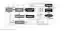
FIG. 1 is a block diagram of the overall RF based wireless energy transfer system with receiver searching and tracking functions,
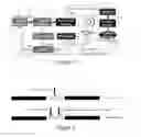
FIG. 2 is a schematic diagram of the modified RFID tag,
FIGS. 3a and 3b show the integration of an RF switch with the RFID tag,
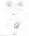
FIG. 4 is radiation pattern of the transmitter in two different states, using a 2×4 array antenna,
FIG. 5 is radiation pattern of the transmitter transmitting at +30 degrees, using an 8 element linear array antenna,
FIG. 6 is radiation pattern of the transmitter split into 2 sub-arrays delivering power to +30 and −30 degrees, using an 8 element linear array antenna, and
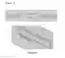
FIG. 7 is a photo of a rectenna.
DETAILED DESCRIPTION
A tracking system uses transmitter with a steerable phased array antenna and an RFID reader, to locate a RFID tag. The Phased array antenna scans different angular sectors and sends power toward those specific sectors during the scanning time. The RFID tag includes a rectenna that receives RF power from phased array antenna and converts it to DC power. If the tag is in the active sector, the rectenna receives the RF power and produces a DC voltage. This voltage switches the RFID tag from being invisible to visible. The RFID reader is constantly scanning for visible tags and logs the current sector when a tag is detected as the tag location.
Sector here is used to mean a discrete angle range, or in terms of beam steering, a sequential series of spaced discrete beam steering angles. For example if detection range is ±80°, and there were 8 sectors, then the beam steering angles for each sector might be −70, −50, −30, −10, 10, 30, 50, 70.
A transmitter 100 is shown in FIG. 1. A phased array with M×N elements 102 transmits RF energy at a first frequency such as an ISM band for example: 2.45 GHz or 5.8 GHz. The signal for the array 102 is generated by signal generator/RF power generator 101 and coupled to each array element via feeding network 103.
A RFID reader 106 transmits at a second frequency such as an RFID band for example: 866-869 MHz or 928-950 -MHz or 2.4-2.5 GHz. A CPU 105 communicates with to the RFID reader 106 and signal generator 101. The CPU 105 is also connected to a control board 107, which in turn connects to the feeding network 103.
The CPU 105 determines the power level to be transmitted by controlling the signal generator 101. The signal sent during scanning may differ in power, frequency etc. compared to the power signal sent once the RFID tag is located. The CPU 105 determines the sector or direction of the array 102 by controlling the feeding network 103. The RFID reader 106 is enabled by the CPU 105 and provides a status signal back to the CPU 105 when a RFID tag is located. The scanning process (and thus power consumption by the RFID reader 106) may be continuous, periodic or may be event activated.
The RFID reader 106 may incorporate a separate antenna or may share the phased array antenna 102 if the first and second frequencies are similar or identical.
The RFID reader 106 may be off the shelf and retrofitted into the system. The RFID tag 104 may include a dipole antenna 111 including an inductive loop 112, and an RFID chip 110 coupled to antenna 111 via the inductive loop 112. The RFID tag 104 may be specifically modified as shown in FIGS. 2, 3a and 3b, depending on the application.
FIG. 2 shows the operation of an unmodified RFID chip; which uses a semi-switching method (modulation) to communicate with RFID reader 106. FIG. 2 also shows a modified RFID tag 104, with an added RF switch 114 in series with an RFID chip 110.
A directional rectenna 109 designed for the second frequency converts any received RF energy from the array 102 and rectifies it into a DC bus 116. The rectenna 109 is shown in more detail in FIG. 7. The rectenna includes a patch radiator 700 fed by an antenna feed 702 and a DC bus 704. A voltage doubler 706 is connected between the antenna feed 702 and the DC bus 704 to rectify the signal from the antenna feed 702 to a DC voltage. Two capacitors 708 are provided to store energy received by the patch radiator 700 and to reduce the ripple on the DC bus 704. An inductor 710 is connected between the voltage doubler 706 and the antenna feed 702 for impedance matching.
The DC bus 116 is connected to the control input of the RF switch 114. As shown in FIG. 2 when the RF switch 114 is closed the loop 112 is closed and enabled, and when is open the loop 112 is open and disabled. When the inductive loop 112 is open, the coupling from the RFID chip 110 to the dipole 111 is insignificant and thus the RFID tag 104 appears invisible to the RFID reader 106. Alternatively if the RFID chip 110 may have an enable or disable input port to which DC bus 116 can be connected. In that case the RFID chip 110 itself is directly disabled rather than indirectly via the RF switch 114.
The modified RFID tag 104 can only be read once the transmitter is transmitting the RF beam toward its corresponding sector. So, the system can detect that a rectenna is located in this sector and the system can either stop at this step or it can continue to find other rectennas in other sectors. After detecting the sector(s) of the available rectenna(s) the system can transmit power toward the detected sector(s).
The DC bus 116 is coupled to the mobile device(s) 118 as shown in FIG. 1. The mobile device(s) 118 or DC bus 116 may incorporate energy storage such a battery or super capacitor to store the received energy from the rectenna 109.
Each RFID chip 110 has its unique ID and this data is stored as the ID of the attached modified RFID tag by CPU 105.
The advantages of using different first and second frequencies are:
1. The TX is sending watt level power. If a single frequency or slightly shifted frequency is used, the TX power may jam detections.
2. Conventional RFID does not support beam steering. In this technology, one frequency is used for beam steering while another frequency at RFID band is used for detection. However, since the detection process and power transmission process are separate from each other, the same frequency for both of these processes can be used.
The system will operate in at least two modes:
1. Searching for Receivers
The TX scans and stores the ID of the read modified tags along with their corresponding sectors. It then can decide that to which of these sectors should transmit power.
2. Power Transmission and Tracking of Receivers
In the course of transmitting power to a rectenna, in some specified intervals the RFID reader tries to read the RFID tag of this rectenna again. If the RFID reader was able to read the modified tag again, TX will continue transmitting power to this rectenna. If not, it means that the rectenna has changed its sector and the system will start searching for the new sector of this rectenna.
The array 102 may deliver power to a single direction. However, it is also possible to configure the feeding network 103 to send multi-beams (>1). With an 8 element linear array, the radiation pattern of transmitting at +30 degrees is plotted in FIG. 5. The feeding network 103 can alternatively split the 8 elements into 2 sub-arrays, each consisting of 4 elements. Radiation pattern of two sub-arrays delivering power to +30 and −30 degrees are plotted in FIG. 6. The penalty of doing this may be wider beam width, since fewer elements are used, and reduced power by a factor of 2.
Moreover, its also possible to steer the beam continuously. As the beam is steered across its complete arc, the RFID reader 106 will continue to monitor for responses by a RFID tag 104. In this scenario the RFID tag 104 may become enabled or detected over a region of beam steering angles, rather than a discrete beam steering angle as described above. The CPU 105 can determine the RFID tag 104 location by either: 1) monitor the start and end angle of the detected region and designate the centre of this region or) determine the beam steering angle at which the RSSI (Received Signal Strength Indication) of the reflected RFID tag signal is highest.
While example embodiments of the invention have been described in detail, many variations are possible within the scope of the invention as claimed as will be clear to a skilled reader.
Claims
What is claimed is:1. A tracking system comprising:
a transmitter configured to steer an RF beam across a detection range,
a passive RFID tag configured to be enabled when the tag and/or an RF antenna is located substantially in the RF beam, and
an RFID reader configured to detect the tag once enabled.
2. The system of claim 1, wherein the tag is configured to connect to the RF antenna and to toggle a switch to enable the tag when the RF antenna is located substantially in the RF beam.
3. The system of claim 2, wherein the antenna is a rectenna.
4. The system in any preceding claims wherein the RF beam is at a first frequency in an ISM band substantially located about 2.45 GHz or 5.80 GHz.
5. The system of claim 1, wherein the RFID reader is configured to detect the tag using a second frequency in an RFID band substantially located about 866-869 MHz, 928-950 MHz or 2.4-2.5 GHz.
6. The system of claim 1, wherein the transmitter comprises a steerable phased array antenna for the RF beam and/or for the RFID reader to detect the tag.
7. The system of claim 3, wherein the rectenna is omni-directional or directive.
8. The system of claim 1, wherein the RF beam is sequentially steered at a series of spaced discrete angles, and if the RFID tag is detected, a tag location is determined as one of the discrete angles.
9. The system of claim 1, wherein the RF beam is continuously steered across the detection range, and if the RFID tag is detected, a tag location is determined as the centre of the range of RF beam steering angles where the RFID tag was detected, or as the angle at which a RSSI is the highest.
10. A method comprising:
scanning a beam of RF radiation over a plurality of sectors;
switching a modified RFID tag from invisible to visible when the tag receives the RF beam is in the currently scanned sector;
detecting visible RFID tags, and
determining the location of the tag of locating a tag relative to the RF beam origin based on the current sector in which an RFID tag can be detected.
11. The method of claim 10 further comprising focusing power RF radiation at the determined location.
12. The method of claim 11 further comprising tracking any change in the determined location.
Images & Drawings included:

Sources:
- United States Patent and Trademark Office - verify current appl. status at the USPTO↗
Similar patent applications:
- » 20230056872
Wavelength tracking system, method to calibrate a wavelength tracking system, lithographic apparatus, method to determine an absolute position of a movable object, and interferometer system - » 20210072088
Wavelength tracking system, method to calibrate a wavelength tracking system, lithographic apparatus, method to determine an absolute position of a movable object, and interferometer system - » 20150109192
IMAGE SENSING SYSTEM, IMAGE SENSING METHOD, EYE TRACKING SYSTEM, EYE TRACKING METHOD - » 20110084808
TRACKING SYSTEMS, METHODS OF LOCATING AND IDENTIFYING RFIDS, AND METHODS OF TRACKING ITEMS - » 20060037832
Adaptable freewheel flow track systems, methods, and apparatus - » 18336899
Target tracking method, system, device and storage medium - » 20080217143
Adaptable Freewheel Flow Track Systems, Methods, and Apparatus - » 20070265994
Document use tracking system, method, computer readable medium, and computer data signal - » 20080140432
VERIFICATION AND DATA-TRACKING SYSTEMS, METHODS, AND DEVICES - » 20060037833
Conveyor flow track systems, methods, and apparatus
Recent applications in this class:
- » 20250292040 2025-09-18
HANDICAPPED PARKING MONITORING SYSTEM - » 20250278585 2025-09-04
WIRELESS TAG READING SYSTEM, WIRELESS TAG READING DEVICE, AND METHOD - » 20250278584 2025-09-04
ASSOCIATING ASSETS USING RFID-RF WIRELESS GATEWAYS - » 20250265427 2025-08-21
WIRELESS TAG COMMUNICATION APPARATUS - » 20250259025 2025-08-14
RFID READ ZONE MAPPING, TESTING, AND MONITORING USING A SILENT RFID TAG - » 20250225351 2025-07-10
Automated removal of security tags - » 20250225350 2025-07-10
COMMUNICATION METHOD AND APPARATUS, AND DEVICE, STORAGE MEDIUM, CHIP, PRODUCT AND PROGRAM - » 20250225349 2025-07-10
RFID-BASED POSITIONING SYSTEM FOR INDOOR ENVIRONMENTS - » 20250217611 2025-07-03
MANAGING LIFECYCLE OF PRODUCTS IN FACILITIES - » 20250217610 2025-07-03
WIRELESS TAG LOCATION
Recent applications for this Assignee:
- » 20250280125 2025-09-04
IMAGE DATA ENCODING AND DECODING - » 20250199527 2025-06-19
INFORMATION PROCESSING DEVICE, INFORMATION PROCESSING METHOD, AND PROGRAM - » 20250175646 2025-05-29
IMAGE PROCESSING APPARATUS AND METHOD - » 20250150244 2025-05-08
INTERFACE CIRCUIT AND INFORMATION PROCESSING SYSTEM - » 20250126294 2025-04-17
IMAGE PROCESSING APPARATUS AND METHOD - » 20250123622 2025-04-17
INFORMATION PROCESSING APPARATUS, INFORMATION PROCESSING METHOD, AND PROGRAM - » 20250119802 2025-04-10
TERMINAL DEVICE AND METHOD - » 20250113080 2025-04-03
REPRODUCING DEVICE, REPRODUCING METHOD, PROGRAM, AND TRANSMITTING DEVICE - » 20250068301 2025-02-27
INFORMATION PROCESSING APPARATUS FOR RESPONDING TO FINGER AND HAND OPERATION INPUTS - » 20250044935 2025-02-06
INFORMATION PROCESSING DEVICE, INFORMATION PROCESSING METHOD, AND PROGRAM