Pinning and affixing nano-active material
US20140128245A1
2014-05-08
14/154,089
2014-01-13
✅ Patent granted
US 9,522,388 B2
2016-12-20
-
-
Anthony J Zimmer | Haytham Soliman
Morrison & Foerster LLP
2035-02-05
Abstract:
A nanoparticle comprises a nano-active material and a nano-support. In some embodiments, the nano-active material is platinum and the nano-support is alumina. Pinning and affixing the nano-active material to the nano-support is achieved by using a high temperature condensation technology. In some embodiments, the high temperature condensation technology is plasma. Typically, a quantity of platinum and a quantity of alumina are loaded into a plasma gun. When the nano-active material bonds with the nano-support, an interface between the nano-active material and the nano-support forms. The interface is a platinum alumina metallic compound, which dramatically changes an ability for the nano-active material to move around on the surface of the nano-support, providing a better bond than that of a wet catalyst. Alternatively, a quantity of carbon is also loaded into the plasma gun. When the nano-active material bonds with the nano-support, the interface formed comprises a platinum copper intermetallic compound, which provides an even stronger bond.
Inventors:
- Qinghua YIN 44 🇺🇸 Tempe, AZ, United States
- Xiwang QI 48 🇺🇸 Scottsdale, AZ, United States
- Eliseo RUIZ 3 🇺🇸 Queen Creek, AZ, United States
Assignee:
- SDCmaterials, Inc. 70 🇺🇸 Tempe, AZ, United States
Applicant:
Interested in similar patents?
Get notified when new applications in this technology area are published.
Classification:
B01J23/8926 » CPC main
Catalysts comprising metals or metal oxides or hydroxides, not provided for in group of the iron group metals or copper combined with noble metals Copper and noble metals
B01J23/89 IPC
Catalysts comprising metals or metal oxides or hydroxides, not provided for in group of the iron group metals or copper combined with noble metals
B01J23/42 » CPC further
Catalysts comprising metals or metal oxides or hydroxides, not provided for in group of noble metals of the platinum group metals Platinum
B01J37/009 » CPC further
Processes, in general, for preparing catalysts; Processes, in general, for activation of catalysts Preparation by separation, e.g. by filtration, decantation, screening
B28B23/0087 » CPC further
Arrangements specially adapted for the production of shaped articles with elements wholly or partly embedded in the moulding material; Production of reinforced objects; Embedding aggregates to obtain particular properties Lightweight aggregates for making lightweight articles
B82Y30/00 » CPC further
Nanotechnology for materials or surface science, e.g. nanocomposites
B82Y40/00 » CPC further
Manufacture or treatment of nanostructures
B01J37/02 IPC
Processes, in general, for preparing catalysts; Processes, in general, for activation of catalysts Impregnation, coating or precipitation
C23C4/134 » CPC further
Coating by spraying the coating material in the molten state, e.g. by flame, plasma or electric discharge characterised by the method of spraying Plasma spraying
B01J35/0013 » CPC further
Catalysts, in general, characterised by their form or physical properties Colloids
B01J37/32 » CPC further
Processes, in general, for preparing catalysts; Processes, in general, for activation of catalysts Freeze drying, i.e. lyophilisation
B01J37/0211 » CPC further
Processes, in general, for preparing catalysts; Processes, in general, for activation of catalysts; Impregnation, coating or precipitation; Impregnation using a colloidal suspension
B01J37/34 IPC
Processes, in general, for preparing catalysts; Processes, in general, for activation of catalysts Irradiation by, or application of, electric, magnetic or wave energy, e.g. ultrasonic waves ; Ionic sputtering; Flame or plasma spraying; Particle radiation
B32B37/14 » CPC further
Methods or apparatus for laminating, e.g. by curing or by ultrasonic bonding characterised by the properties of the layers
B01J23/00 IPC
Catalysts comprising metals or metal oxides or hydroxides, not provided for in group
B01J35/00 IPC
Catalysts, in general, characterised by their form or physical properties
B01J37/00 » CPC further
Processes, in general, for preparing catalysts; Processes, in general, for activation of catalysts
B28B23/00 IPC
Arrangements specially adapted for the production of shaped articles with elements wholly or partly embedded in the moulding material; Production of reinforced objects
B32B7/12 » CPC further
Layered products characterised by the relation between layers; Layered products characterised by the relative orientation of features between layers, or by the relative values of a measurable parameter between layers, i.e. products comprising layers having different physical, chemical or physicochemical properties; Layered products characterised by the interconnection of layers; Interconnection of layers using interposed adhesives or interposed materials with bonding properties
B01J37/349 » CPC further
Processes, in general, for preparing catalysts; Processes, in general, for activation of catalysts; Irradiation by, or application of, electric, magnetic or wave energy, e.g. ultrasonic waves ; Ionic sputtering; Flame or plasma spraying; Particle radiation making use of flames, plasmas or lasers
Description
CROSS REFERENCE TO RELATED APPLICATIONS:
This application claims priority under 35 U.S.C. §119(e) to co-pending Provisional U.S. Patent Application No. 61/284,329, filed Dec. 15, 2009, and entitled “MATERIAL PROCESSING,” which is hereby incorporated by reference.
FIELD OF THE INVENTION
The present invention relates to the field of catalysts. More specifically, the present invention relates to methods of pinning and affixing nano-active material to a nano-support.
BACKGROUND OF THE INVENTION
Catalysts are used to facilitate and speed up a reaction. For example, using well-known methods of wet chemistry to form a catalyst, extrudates are placed in hexachlorplatinic acid (H2PtCl6). In some embodiments, an extrudate is a cylindrical pellet made by an extrusion process. An example of an extrudate 100 is shown in FIG. 1A. The extrudate 100 is made of or is coated with alumina (Al2O3) and thus has available oxygen (O) atoms 105 on its surface. As illustrated in FIG. 1B, the platinum (Pt) atoms 115 of the hexachlorplatinic acid 110 are chemically absorbed onto the surface of the alumina. In particular, drying and calcining, such as in an oven, allows the platinum atoms 115 to bond to the oxygen atoms 105, with HCl molecules as byproduct. However, the platinum atoms 115 are not fixed to their bonded oxygen atoms 105 and are able to move around to other available oxygen atoms 105 as illustrated in FIGS. 1C-1D. As the platinum atoms 115 move, the platinum atoms 115 begin to coalesce with other platinum atoms resulting in larger particles 120, as shown in FIG. 1E, and a more energetically favorable state. It is understood that as the platinum particles become larger, it detrimentally affects the ability of the material to act as a catalyst. In high temperature applications, such as in an aged catalytic converting testing, the movement of platinum atoms is magnified. What is needed is an interface and method to prevent the platinum atoms from coalescing.
SUMMARY OF THE INVENTION
In one aspect, an interface for pinning a nano-active material to a nano-support includes a compound configured to limit movement of the nano-active material on a surface of the nano-support. The compound is formed by a reaction of the nano-active material and the surface of the nano-support. In some embodiments, the nano-active material is platinum and the nano-support is alumina. In some embodiments, the nano-support comprises a partially reduced alumina surface. In other embodiments, the compound is a platinum alumina metallic compound. Alternatively, the compound is a platinum copper intermetallic compound.
In another aspect, a pinning method to affix nano-active materials to nano-supports uses a high temperature condensation technology. The high temperature condensation technology is eBeam, microwave, RF or DC plasma. The nano-active materials and the nano-supports are gathered. In some embodiments, starting materials, including a quantity of catalyst material and a quantity of carrier material, are loaded into a chamber. The quantity of catalyst material and the quantity of carrier material are vaporized to create the nano-active materials and the nano-supports. In some embodiments, working gas is supplied to the chamber and energy is delivered to the working gas to form a highly reactive and energetic mixture such that the quantity of catalyst material and the quantity of carrier material are vaporized. In some embodiments, a quantity of copper is also loaded into the chamber to be vaporized.
Metallic properties on surfaces of the nano-supports are then increased. An interface between each nano-active material and a nano-support is formed. The interface is configured to limit movement of the nano-active material on the surface of the nano-support. In some embodiments, each of the plurality of nano-active materials is platinum. In some embodiments, each of the plurality of nano-supports is alumina. In some embodiments, each of the plurality of nano-supports comprises a partially reduce alumina surface. In other embodiments, the interface includes a platinum alumina metallic compound or a platinum copper intermetallic compound.
In yet another aspect, a method of affixing a nano-active material to a nano-support uses high temperature condensation technology to form a layer between the nano-active material and the nano-support material. The high temperature condensation technology is eBeam, microwave, RF or DC plasma. In some embodiments, starting materials, including catalyst material and carrier material, are loaded into a chamber and are vaporized to create the nano-active material and the nano-support. In other embodiments, copper is also loaded into the chamber to be vaporized. Typically, the layer between the nano-active material and the nano-support material is configured to limit movement of the nano-active material on a surface of the nano-support. In some embodiments, the layer includes a platinum alumina metallic compound. Alternatively, the layer includes a platinum copper intermetallic compound.
BRIEF DESCRIPTION OF THE DRAWINGS:
FIGS. 1A-1E illustrate a wet catalyst and its properties in the prior art.
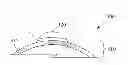
FIG. 2 illustrates a process 200 of pinning and affixing nano-active material to nano-support in accordance with the present invention.
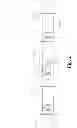
FIGS. 3A-3B illustrate a nanoparticle in accordance with the present invention.
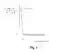
FIG. 4 illustrates a graph of difference of activity of fresh and aged plasma catalysts versus a ratio of copper to platinum in the plasma catalyst.
DETAILED DESCRIPTION OF THE INVENTION
Reference will now be made in detail to implementations of the present invention as illustrated in the accompanying drawings. The drawings may not be to scale. The same reference indicators will be used throughout the drawings and the following detailed description to refer to identical or like elements. In the interest of clarity, not all of the routine features of the implementations described herein are shown and described. It will, of course, be appreciated that in the development of any such actual implementation, numerous implementation-specific decisions must be made in order to achieve the developer's specific goals, such as compliance with application, safety regulations and business related constraints, and that these specific goals will vary from one implementation to another and from one developer to another. Moreover, it will be appreciated that such a development effort will be a routine undertaking of engineering for those of ordinary skill in the art having the benefit of this disclosure.
The following description of the invention is provided as an enabling teaching which includes various embodiments. One skilled in the relevant arts, including but not limited to chemistry and physics, will recognize that many changes can be made to the embodiments described, while still obtaining the beneficial results of the present invention. It will also be apparent that some of the desired benefits of the present invention can be obtained by selecting some of the features of the present invention without utilizing other features. Accordingly, those who work in the art will recognize that many modifications and adaptations to the embodiments are possible and may even be desirable in certain circumstances, and are a part of the present invention. Thus, the following description is provided as illustrative of the principles of the present invention and not in limitation thereof, since the scope of the present invention is defined by the claims.
Embodiments of the present invention are directed to pinning and affixing nano-active material to nano-support using a high temperature condensation technology. In some embodiments, the high temperature condensation technology is plasma. The high temperature condensation technology can be eBeam, microwave, RF or DC plasma, or any other high temperature condensation technology are possible. Plasma catalyst formed by using the methods described below advantageously has an interface between a nano-active material and a support. As explained in more detail below, the interface dramatically reduces the ability for the nano-active material to move around on the surface of the support, thereby prevent, or at least minimizing, agglomerations of the nano-active material.
FIG. 2 illustrates a process 200 of pinning and affixing nano-active material to nano-support in accordance with an embodiment of the present invention. At a step 210, starting materials are introduced into a plasma gun. Typically, a quantity of a catalyst material 212 is loaded into a plasma gun 215. Preferably, the catalyst material 212 comprises platinum (Pt), which has excellent catalytic properties. A quantity of carrier material 214 is also loaded into the plasma gun 215. In some embodiments, the carrier material 214 is an oxide such as alumina (Al2O3). Other useful oxides will be apparent to those of ordinary skill. In some embodiments, the catalyst material 212 and the carrier material 214 are loaded manually into a hopper (not shown), which automatically loads the materials into the plasma gun 215. Alternatively, an automated system is able to load the catalyst material 212 and carrier material 214 into the plasma gun 215. In some embodiments, the starting materials are in powder form when they are loaded into the plasma gun 215. Alternatively, the starting materials are loaded into the plasma gun 215 in other forms (e.g., wire, liquid and gas) are contemplated. It should be understood to one skilled in the art that the ratio of the catalyst material 212 to the carrier material 214 can be adjusted to meet particular demands of a given application. Typically, the quantity of the carrier material 214 is much greater than the quantity of the catalyst material 212.
Next, at a step 220, the plasma gun 215 vaporizes the catalyst material 212 along with the carrier material 214 to form a vapor cloud 225. In some embodiments, working gas is introduced into the plasma gun, while energy is supplied to the working gas to create plasma. A variety of different means can be employed to deliver this energy, including, but not limited to, DC coupling, capacitive coupling, inductive coupling, and resonant coupling. The combination within the plasma gun 215 of the plasma and the materials forms a highly reactive and energetic mixture, wherein the materials can be vaporized. The vapor cloud 225 comprises both vaporized catalyst material and vaporized carrier material in the ratio that was loaded into the plasma gun 215 at the step 210.
Still referring to FIG. 2, the resulting vapor cloud 225 is then put through a quenching step 230. Preferably, the quenching step occurs in a highly turbulent quench chamber to facilitate rapid, even, consistent quenching of the vapor 225 into precipitate nanoparticles 300. As the catalyst material 212 and carrier material 214 cool, they solidify into nanoparticles 300. An example of a resulting nanoparticle 300 is shown in FIG. 3A. As shown, the nanoparticle 300 comprises a nano-active material 320 and a nano-support 310. In some embodiments, the nano-active material 320 is a gaseous platinum atom, and the nano-support 310 is some form of alumina, such as aluminum (Al) plus oxygen (O).
Specifically, the vaporizing and quenching is performed in reducing conditions using plasma from argon H2. As the vapor 225 quenches, the catalyst material 212 starts to cool down to form nano-active material 320 during quenching. Meanwhile, the carrier material 214 forms into a nano-support 310 with a partially reduced alumina surface, resulting in a more metallic and less oxygen-rich surface. At the surface, the partially reduced alumina is of Al2O3−x, wherein x is an integer that ranges from zero to three.
Generally the ratio of the nano-active materials 320 and the nano-supports 310 is determined by the ratio of the starting quantities of the catalyst material 212 and carrier material 214 in step 210 of FIG. 2. As such, there are many more nano-supports 310 than there are nano-active materials 320. Although nano-active materials 320 are able to collide with other nano-active materials 320, the chances are greater that the nano-supports 310 collide with other nano-supports 310. The next most likely occurrence are the nano-active materials 320 colliding with the nano-supports 310, resulting in nanoparticles 300.
FIG. 3B illustrates a cross-sectional view of the nanoparticle 300. Since the surface of the nano-support 310 is partially reduced alumina, the nano-active material 320 reacts with the aluminum metal (more so than with the aluminum oxide). As such, when a nano-active material 320 attaches to the surface 315 of a nano-support 310, an interface 325 is formed by the reaction of the nano-active material 320 and the partially reduced alumina. In some embodiments, the interface 325 thereby comprises a platinum alumina metallic compound (PtaAlb). The platinum alumina metallic compound changes dramatically the ability for the nano-active material 320 to move around on the surface 315 of the nano-support 310. Consequently, the nano-active material 320 strongly attaches to the nano-support 310, preventing the movement and coalescing/conglomeration of the nano-active material 320 on the surface of the nano-support 310. In contrast to the plasma catalyst of the present invention, nano-active materials of a wet catalyst formed using wet chemistry are free to move and conglomerate. As discussed above, the prevention of movement and coalescing/conglomeration is of great benefit in high temperature applications such as in an aged catalytic converting testing.
When using wet chemistry to form a wet catalyst, a problem arises in high temperature applications, such as in the aged catalytic converting testing in which the temperature was raised to 800° C. The degree of platinum conglomeration in the wet catalyst was magnified compared to that of fresh catalytic converting testing, whereas the difference between conglomerations in aged and fresh catalytic converting testing was much lower in the plasma catalyst. This was true when the testing is done in both reducing and oxidation conditions. The increase in the amount of conglomeration of the aged plasma catalyst raised to 800° is equivalent to the amount of the wet catalyst raised to only 20° to 50° C.
In some embodiments, the effectiveness and activity of the plasma catalyst is further improved by adding a quantity of copper (Cu) into the plasma gun 215 along with the other starting materials 212, 214. FIG. 4 illustrates a graph of difference of activity of fresh and aged plasma catalysts versus a ratio of copper to platinum in the plasma catalyst. With a certain copper to platinum ratio, typically 0.4, in the plasma catalyst, an increase in conglomeration is even lower, typically equivalent to only a 1° C. to 5° C. raise in the wet catalysts. When copper is added, the interface between the nano-active material 320 and the surface 315 of the nano-support 310 comprises a platinum copper intermetallic compound (IMC), which consequently provides a better bond than an interface containing a platinum alumina metallic compound since the tendency of platinum atoms to skip over to an available oxygen atom is further reduced.
The present invention has been described in terms of specific embodiments incorporating details to facilitate the understanding of principles of construction and operation of the invention. Such reference herein to specific embodiments and details thereof is not intended to limit the scope of the claims appended hereto. A person skilled in the art would appreciate that various modifications and revisions to the pinning and affixing nano-active material. Consequently, the claims should be broadly construed, consistent with the spirit and scope of the invention, and should not be limited to their exact, literal meaning.
Claims
We claim:1. An interface for pinning nano-active material to nano-support comprising a compound configured to limit movement of the nano-active material on a surface of the nano-support, wherein the compound is formed by a reaction of the nano-active material and the surface of the nano-support.
2. The interface of claim 1 wherein the nano-active material is platinum.
3. The interface of claim 1 wherein the nano-support is alumina.
4. The interface of claim 1 wherein the nano-support comprises a partially reduced alumina surface.
5. The interface of claim 1 wherein the compound is a platinum alumina metallic compound or a platinum copper intermetallic compound.
6. A pinning method to affix nano-active materials to nano-supports by using a high temperature condensation technology comprising:
a. gathering the nano-active materials and the nano-supports;
b. increasing metallic properties on surfaces of the nano-supports; and
c. forming an interface between each nano-active material and a nano-support, wherein the interface is configured to limit movement of the nano-active material on the surface of the nano-support.
7. The pinning method of claim 6 wherein the high temperature condensation technology is eBeam, microwave, RF or DC plasma.
8. The pinning method of claim 6 wherein the gathering includes:
a. loading a quantity of catalyst material and a quantity of carrier material into a chamber; and
b. vaporizing the quantity of catalyst material and the quantity of carrier material, thereby creating the nano-active materials and the nano-supports.
9. The pinning method of claim 8 wherein the vaporizing includes:
a. supplying working gas into the chamber; and
b. delivering energy to the working gas.
10. The pinning method of claim 8 wherein the gathering further includes loading a quantity of copper into the chamber.
11. The pinning method of claim 6 wherein each of the plurality of nano-active materials is platinum.
12. The pinning method of claim 6 wherein each of the plurality of nano-supports is alumina.
13. The pinning method of claim 6 wherein each of the plurality of nano-supports comprises a partially reduce alumina surface.
14. The pinning method of claim 13 wherein the interface comprises a platinum alumina metallic compound or a platinum copper intermetallic compound.
15. A method of affixing a nano-active material to a nano-support comprising using high temperature condensation technology to form a layer between the nano-active material and the nano-support material.
16. The method of claim 15 wherein the high temperature condensation technology is eBeam, microwave, RF or DC plasma.
17. The method of claim 15 wherein the using comprises:
a. loading catalyst material and carrier material into a chamber; and
b. vaporizing the catalyst material and the carrier material to create the nano-active material and the nano-support.
18. The method of claim 17 wherein the using further comprising loading copper into the chamber.
19. The method of claim 15 wherein the layer is configured to limit movement of the nano-active material on a surface of the nano-support.
20. The method of claim 19 wherein the layer comprises a platinum alumina metallic compound or comprises a platinum copper intermetallic compound.
Images & Drawings included:


Sources:
- United States Patent and Trademark Office - verify current appl. status at the USPTO↗
Similar patent applications:
- » 20110143915
Pinning and affixing nano-active material
Recent applications in this class:
- » 20250214064 2025-07-03
CO TO CO2 COMBUSTION PROMOTER - » 20250108363 2025-04-03
PLASMA-TREATED CATALYST, PRODUCTION METHOD THEREOF AND USE OF THE CATALYST - » 20240408584 2024-12-12
REDUCTIVE AMINATION CATALYST FOR PREPARATION OF POLYETHER AMINE AND ITS PREPARATION METHOD - » 20240399345 2024-12-05
APPARATUS FOR REDUCING NOx AND METHOD FOR PREPARING A CATALYST FOR REDUCING NOx - » 20240261768 2024-08-08
POLYNORBORNENE/CARBON BLACK-CROSS-LINKED THREE-DIMENSIONAL NETWORK-IMMOBILIZED COPPER/GOLD (PNBI/CB-Cu/Au) NANOCATALYST, AND PREPARATION METHOD AND USE THEREOF - » 20240207826 2024-06-27
NOVEL NANOPARTICLE ALLOYS AND CATALYTIC COMPOSITIONS COMPRISING THE SAME FOR EMISSION CONTROLS - » 20240165595 2024-05-23
CO to COcombustion promoter - » 20230398523 2023-12-14
METHOD FOR MANUFACTURING CATALYST FOR MANUFACTURE OF VINYL ACETATE AND METHOD FOR MANUFACTURING VINYL ACETATE - » 20230113708 2023-04-13
Zoned catalysts for CNG engine exhaust gas treatments with improved ammonia emission control - » 20230074054 2023-03-09
INHIBITION-FREE LOW-TEMPERATURE ENGINE EXHAUST OXIDATION CATALYST
Recent applications for this Assignee:
- » 20170028393 2017-02-02
Method and system for forming plug and play metal catalysts - » 20160310930 2016-10-27
Catalyst design for heavy-duty diesel combustion engines - » 20160184802 2016-06-30
Method and system for forming plug and play metal compound catalysts - » 20160144352 2016-05-26
Wet chemical and plasma methods of forming stable PTPD catalysts - » 20160144346 2016-05-26
Method and system for forming plug and play oxide catalysts - » 20160138870 2016-05-19
Highly turbulent quench chamber - » 20160074855 2016-03-17
Three-way catalytic converter using nanoparticles - » 20160067679 2016-03-10
Advanced catalysts for automotive applications - » 20160059216 2016-03-03
Three-way catalytic converter using nanoparticles - » 20150266002 2015-09-24
Compositions for passive NOadsorption (PNA) systems and methods of making and using same