Sheet cutting apparatus and sheet cutting method using the same
US20140130647A1
2014-05-15
14/011,490
2013-08-27
✅ Patent granted
US 9,399,305 B2
2016-07-26
-
-
Ghassem Alie | Bharat C Patel
Knobbe, Martens, Olson & Bear, LLP
2034-03-01
Abstract:
A sheet cutting apparatus and a sheet cutting method using the same are disclosed. In one aspect, the sheet cutting apparatus includes a holder for rotatably supporting a sheet roll, a lamination unit for pulling and unwinding a front end of the sheet unwound from the sheet roll, a table on which the sheet unwound by the lamination parts is attached, and a tension unit for giving tension to the sheet attached on the table. Since the sheet cutting apparatus may cut the sheet consistently and stably, product quality and production efficiency should increase.
Inventors:
- Choong-Ho Lee 42 🇰🇷 Yongin-CIty, South Korea
- Doh-Hyoung Lee 4 🇰🇷 Yongin-City, South Korea
- Sung-Sik Yun 4 🇰🇷 Yongin-City, South Korea
- Tong-Jin Park 4 🇰🇷 Yongin-City, South Korea
- Choong-Ho Lee 38 🇰🇷 Yongin, South Korea
- Sung-Sik Yun 4 🇰🇷 Yongin, South Korea
- Tong-Jin Park 4 🇰🇷 Yongin, South Korea
- Doh-Hyoung Lee 4 🇰🇷 Yongin, South Korea
Assignee:
- SAMSUNG DISPLAY CO., LTD. 2,765 🇰🇷 Yongin-City, South Korea
- SAMSUNG DISPLAY CO., LTD. 4,003 🇰🇷 Gyeonggi-do, South Korea
Applicant:
Interested in similar patents?
Get notified when new applications in this technology area are published.
Classification:
B26D7/015 » CPC further
Details of apparatus for cutting, cutting-out, stamping-out, punching, perforating, or severing by means other than cutting; Means for holding or positioning work for sheet material or piles of sheets
Y10T83/0424 » CPC further
Cutting; Processes; With preparatory or simultaneous ancillary treatment of work; By distorting within elastic limit By stretching
B26D5/00 IPC
Arrangements for operating and controlling machines or devices for cutting, cutting-out, stamping-out, punching, perforating, or severing by means other than cutting
B26D1/00 » CPC further
Cutting through work characterised by the nature or movement of the cutting member or particular materials not otherwise provided for ; Apparatus or machines therefor; Cutting members therefor
Y10T83/323 » CPC further
Cutting With means to stretch work temporarily
B26D7/14 » CPC main
Details of apparatus for cutting, cutting-out, stamping-out, punching, perforating, or severing by means other than cutting; Means for treating work or cutting member to facilitate cutting by tensioning the work
B23Q15/00 IPC
Measuring; Indicating; Controlling
B23Q15/00 IPC
Automatic control or regulation of feed movement, cutting velocity or position of tool or work
B29C65/00 IPC
Joining of preformed parts ; Apparatus therefor
B29C69/00 IPC
Combinations of shaping techniques not provided for in a single one of main groups - , e.g. associations of moulding and joining techniques; Apparatus therefore
B65H81/00 IPC
Methods, apparatus, or devices for covering or wrapping cores by winding webs, tapes, or filamentary material, not otherwise provided for
B26D7/01 IPC
Details of apparatus for cutting, cutting-out, stamping-out, punching, perforating, or severing by means other than cutting Means for holding or positioning work
Description
CROSS-REFERENCE TO RELATED PATENT APPLICATION
This application claims the benefit of Korean Patent Application No. 10-2012-0128374, filed on Nov. 13, 2012, in the Korean Intellectual Property Office, the disclosure of which is incorporated herein in its entirety by reference.
BACKGROUND
1. Field
The described technology generally relates to a sheet cutting apparatus to cut rolls of metal sheets into standard sheets.
2. Description of the Related Technology
Generally, metal masks are used for color patterning of organic light-emitting devices (OLEDs), and producing metal masks may require cutting rolled metal sheets into standard sheets.
SUMMARY
One inventive aspect is an improved sheet cutting apparatus and a sheet cutting method using the same to cut rolled metal sheets into standard sheets.
Another aspect is a sheet cutting apparatus, which includes: a holder for rotatably supporting a sheet roll; a lamination unit for pulling and unwinding a front end of a sheet from the sheet roll; a table on which the sheet unwound by the lamination unit is attached; and a tension unit for applying tension to the sheet attached on the table.
The tension unit is installed between the holder and the table and may include a tension roller for providing backward tension on the sheet spread on the table.
The lamination unit may include a pair of lamination rollers for grasping a front end of the sheet roll and a guide unit for guiding the pair of lamination rollers to travel on the table.
The guide unit may guide the lamination rollers along a circular path so that the lamination rollers may go forward and then descend without contacting the table and may come backward while contacting the table.
A cutter for cutting a rear end of the sheet attached on the table may be additionally included.
Another aspect is a sheet cutting method which includes: pulling and unwinding a front end of a sheet from a sheet roll; attaching the unwound sheet on a table; applying tension to the sheet while the sheet is attached on the table; and cutting a rear end of the sheet attached on the table.
The pulling and unwinding the sheet from the sheet roll and attaching the unwound sheet on the table may be performed by movement of the pair of lamination rollers having grasped the front end of the sheet.
The pair of lamination rollers may go forward and then descend without contacting the table, to thus make the front end of the sheet contact on the table, and may come backward without contacting the table, to then press the sheet on the table.
The sheet cutting apparatus and the sheet cutting method using the same according to the present invention may cut rolled sheets consistently and stably. Therefore, stabilization of product quality and an increase of producing efficiency may be expected in case of adopting the present invention.
BRIEF DESCRIPTION OF THE DRAWINGS
FIG. 1 is a schematic view showing a structure of a sheet cutting apparatus according to an embodiment.
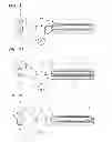
FIGS. 2A through 2D are schematic views illustrating a cutting process by the sheet cutting apparatus shown in FIG. 1 in consecutive order.
DETAILED DESCRIPTION
Generally, if rolled metal sheets are not pulled and spread tensely in a cutting process, it might be hard to cut sheets into standard sheets. It induces productivity to be sharply decreased because of an increased defective rate of sheets.
Embodiments will now be described more fully with reference to the accompanying drawings. A sheet cutting apparatus according to an embodiment will be described with reference to FIG. 1.
As shown in FIG. 1, the sheet cutting apparatus according to the present embodiment includes a holder 100, a lamination unit 300, a table 400, and a tension unit (or a tensioner) 200. The holder 100 rotatably supports a sheet roll 10 around which a sheet is wound in a roll form. The lamination unit 300 clamps and unwinds a front end 11a of the sheet 11 from the sheet roll 10. The sheet 11 unwound by the lamination unit 300 is attached on the table 400. The tension unit 200 gives tension to the sheet 11 attached on the table 400.
The tension unit 200 gives tight tension to the sheet 11 to thus substantially prevent the sheet 11 from wrinkling in a non-uniformed form when the lamination unit 300 unwinds the sheet 11 from the sheet roll 10 which is mounted on the holder 100 to then be attached on the table 400. In this state, a cutter 500 shown in FIG. 2D cuts a rear end 11b of the sheet 11 shown in FIG. 2D. The tension unit 200 gives backward tension to the sheet 11 attached on the table 400. The tension unit 200 includes a tension roller 210 that gives tension to the sheet 11 by pressing the sheet 11 downward as shown in FIG. 1. Therefore, the tension applied on the sheet 11 may be controlled gradually by location of the tension roller 210.
The lamination unit 300 includes a pair of lamination rollers 310 and 320 that grasp a front end 11a of the sheet 11, and a guide unit 330 for guiding the rollers 310 and 320 to travel on the table 400. In one embodiment, the pair of lamination rollers 310 and 320 move along the guide unit 330 at a state where they clamp the front end 11a of the sheet 11, to thus unwind the sheet 11 form the sheet roll 10 and substantially simultaneously press the unwound sheet 11 to then be attached on the table 400. This process is performed when the lamination rollers 310 and 320 circulate along the guide unit 330 and will be described again later.
Reference numeral 220 denotes guide rollers of the tension unit 200 and the sheet 11 may be a metallic material such as Invar.
The sheet cutting apparatus as constructed above may be used as follows. First, the sheet roll 10 is mounted on the holder 100. Then, the front end 11a of the sheet 11 unwound from the sheet roll 10 is clamped on the lamination rollers 310 and 320 through the tension roller 210 as shown in FIG. 1. After the above preparation has been completed, the lamination rollers 310 and 320 are made to move along the guide unit 330 as shown in FIG. 2A. Then, the sheet roll 10 revolves along with movement of the lamination rollers 310 and 320, to thus unwind the sheet 11 from the sheet roll 10. In this process, the lamination rollers 310 and 320 pass above the table 400 without contacting the table 400. While the lamination rollers 310 and 320 may be made to substantially constantly move along the guide unit 330, they may descend and press the clamped front end 11a of the sheet 11 on the table 400 to then be attached on the table 400 as shown in FIG. 2B. Then, the two lamination rollers 310 and 320 are separated from each other to thus unclamp the front end 11a of the sheet 11.
When the lamination rollers 310 and 320 move back to the initial position in this state above as described in the FIG. 2C, the lamination rollers 310 and 320 press the sheet 11 unwound from the sheet roll 10 sequentially, to then be attached on the table 400. The sheet 11 is prevented from wrinkling in a non-uniform shape since the tension roller 210 gives tight tension to the sheet 11 during the process.
The standard sheets may be produced after the rear end 11b of the sheet 11 attached on the table 400 is cut by the cutter 500, as shown in FIG. 2D. Since the sheet 11 may be cut at a tight tensioned state, it may be possible to produce the exact standard sheets stably.
According to at least one of the disclosed embodiments, the sheet cutting apparatus described above may cut the sheet consistently and stably, and thus stabilization of product quality and producing efficiency may increase.
While the above embodiments have been described with reference to the accompanying drawings, it will be understood by those of ordinary skill in the art that various changes in form and details may be made therein without departing from the spirit and scope of the present invention as defined by the following claims.
Claims
What is claimed is:1. A sheet cutting apparatus comprising:
a holder configured to rotatably support a sheet roll;
a lamination unit configured to pull and unwind a front end of a sheet from the sheet roll;
a table on which the sheet unwound by the lamination unit is attached; and
a tensioner configured to provide tension to the sheet attached on the table
2. The apparatus of claim1, wherein the tension unit is installed between the holder and the table and wherein the tension unit further comprises a tension roller configured to provide backward tension to the sheet attached on the table
3. The apparatus of claim1, wherein the lamination unit further comprises:
a pair of lamination rollers configured to grasp a front end of the sheet roll; and
a guide unit configured to guide the pair of lamination rollers to travel on the table.
4. The apparatus of claim1, wherein the guide unit is configured to guide the lamination rollers along a circular path so that the lamination rollers go forward and then descend without contacting the table and come backward while contacting the table.
5. The apparatus of claim1, further comprising a cutter configured to cut a rear end of the sheet attached on the table.
6. A sheet cutting method comprising:
pulling and unwinding a front end of a sheet from a sheet roll,
attaching the unwound sheet on a table,
giving tension to the sheet while the sheet is attached on the table, and
cutting a rear end of the sheet attached on the table.
7. The method of claim 6, wherein the pulling and unwinding and the attaching are performed by movement of the pair of lamination rollers having grasped the front end of the sheet.
8. The method of claim 7, wherein the lamination rollers are configured to 1) move forward and then descend such that a front end of the sheet contacts the table and 2) move backward while contacting the table to compressively attach the sheet to the table
Images & Drawings included:


Sources:
- United States Patent and Trademark Office - verify current appl. status at the USPTO↗
Similar patent applications:
Recent applications in this class:
- » 20240278447 2024-08-22
OBJECT CUTTING DEVICE FOR MANUFACTURE OF COMPOSITE MATERIALS - » 20240009878 2024-01-11
APPARATUS FOR TENSIONING A CABLE LACING TAPE - » 20210086388 2021-03-25
Notching apparatus and method for secondary battery - » 20190358844 2019-11-28
Device and method of forming an opening in a baby bottle nipple - » 20190337179 2019-11-07
Cutting mechanism for roll fiber product - » 20190054646 2019-02-21
CUTTING DEVICE WITH A COMPRESSION WHEEL - » 20170151687 2017-06-01
FILM CUTTER ASSEMBLY - » 20160288357 2016-10-06
BANNER TRIMMING MACHINE - » 20160023367 2016-01-28
Tensioning device for rotary cutting apparatus - » 20150202787 2015-07-23
Device and method for cutting plastic material, in particular a laminated glazing element
Recent applications for this Assignee:
- » 20250180921 2025-06-05
APPARATUS FOR MANUFACTURING DISPLAY DEVICE - » 20250126893 2025-04-17
DISPLAY DEVICE AND METHOD OF MANUFACTURING THE SAME - » 20250104613 2025-03-27
PIXEL AND DISPLAY DEVICE INCLUDING THE SAME - » 20250104610 2025-03-27
PIXEL OF A DISPLAY DEVICE AND DISPLAY DEVICE - » 20250104608 2025-03-27
DISPLAY DEVICE, DRIVE CONTROLLER, AND DISPLAY DEVICE DRIVING METHOD - » 20250104601 2025-03-27
Method of compressing stress data, encoder, display driver and display device - » 20250095525 2025-03-20
METHOD OF DETERMINING A GATE VOLTAGE OF A DISPLAY DEVICE, AND DISPLAY DEVICE - » 20250046258 2025-02-06
DATA DRIVER, DISPLAY DEVICE INCLUDING THE SAME, AND METHOD FOR DRIVING DISPLAY DEVICE - » 20250029545 2025-01-23
Electronic device, display device, and driving method thereof - » 20250028204 2025-01-23
Display device