Spacerless artificial disc replacements
US20140148906A1
2014-05-29
14/169,657
2014-01-31
✅ Patent granted
US 9,198,773 B2
2015-12-01
-
-
David H Willse | Javier Blanco
Lerner, David, Littenberg, Krumholz & Mentlik, LLP
2034-01-31
Abstract:
Spacerless artificial disc replacements (ADR) are disclosed. One preferred embodiment includes two saddle-shaped components to facilitate more normal spinal flexion, extension, and lateral bending while limit axial rotation, thereby protecting the facet joints and the annulus fibrosus (AF). Either or both of the superior and inferior components are made of a hard material such as chrome cobalt, titanium, or a ceramic including alumina, zirconia, or calcium phosphate. The articulating surfaces of the ADR are also preferably highly polished to reduce friction between the components. Metals, alloys or other materials with shape-memory characteristics may also prove beneficial.
Inventors:
- Bret A. Ferree 132 🇺🇸 Cincinnati, OH, United States
- David Tompkins 8 🇺🇸 Newport, KY, United States
Assignee:
- SPINECORE, INC. 67 🇺🇸 Allendale, NJ, United States
Applicant:
Interested in similar patents?
Get notified when new applications in this technology area are published.
Classification:
A61F2/4425 » CPC main
Filters implantable into blood vessels; Prostheses, i.e. artificial substitutes or replacements for parts of the body; Appliances for connecting them with the body; Devices providing patency to, or preventing collapsing of, tubular structures of the body, e.g. stents; Prostheses implantable into the body; Joints for the spine, e.g. vertebrae, spinal discs; Intervertebral or spinal discs, e.g. resilient made of articulated components
A61F2/44 IPC
Filters implantable into blood vessels; Prostheses, i.e. artificial substitutes or replacements for parts of the body; Appliances for connecting them with the body; Devices providing patency to, or preventing collapsing of, tubular structures of the body, e.g. stents; Prostheses implantable into the body; Joints for the spine, e.g. vertebrae, spinal discs
A61F2220/0025 » CPC further
Fixations or connections for prostheses classified in groups - or or or or subgroups thereof Connections or couplings between prosthetic parts, e.g. between modular parts; Connecting elements
A61F2/30 IPC
Filters implantable into blood vessels; Prostheses, i.e. artificial substitutes or replacements for parts of the body; Appliances for connecting them with the body; Devices providing patency to, or preventing collapsing of, tubular structures of the body, e.g. stents; Prostheses implantable into the body Joints
A61F2/30767 » CPC further
Filters implantable into blood vessels; Prostheses, i.e. artificial substitutes or replacements for parts of the body; Appliances for connecting them with the body; Devices providing patency to, or preventing collapsing of, tubular structures of the body, e.g. stents; Prostheses implantable into the body; Joints Special external or bone-contacting surface, e.g. coating for improving bone ingrowth
A61F2/442 » CPC further
Filters implantable into blood vessels; Prostheses, i.e. artificial substitutes or replacements for parts of the body; Appliances for connecting them with the body; Devices providing patency to, or preventing collapsing of, tubular structures of the body, e.g. stents; Prostheses implantable into the body; Joints for the spine, e.g. vertebrae, spinal discs Intervertebral or spinal discs, e.g. resilient
A61L27/10 » CPC further
Materials for prostheses or for coating prostheses; Inorganic materials Ceramics or glasses
A61F2002/30092 » CPC further
Filters implantable into blood vessels; Prostheses, i.e. artificial substitutes or replacements for parts of the body; Appliances for connecting them with the body; Devices providing patency to, or preventing collapsing of, tubular structures of the body, e.g. stents; Prostheses implantable into the body; Joints; Additional features of subject-matter classified in , and subgroups thereof; Material related properties of the prosthesis or of a coating on the prosthesis; Properties of materials and coating materials using shape memory or superelastic materials, e.g. nitinol
A61F2002/30301 » CPC further
Filters implantable into blood vessels; Prostheses, i.e. artificial substitutes or replacements for parts of the body; Appliances for connecting them with the body; Devices providing patency to, or preventing collapsing of, tubular structures of the body, e.g. stents; Prostheses implantable into the body; Joints; Additional features of subject-matter classified in , and subgroups thereof; Shapes; Three-dimensional shapes saddle-shaped
A61F2002/30878 » CPC further
Filters implantable into blood vessels; Prostheses, i.e. artificial substitutes or replacements for parts of the body; Appliances for connecting them with the body; Devices providing patency to, or preventing collapsing of, tubular structures of the body, e.g. stents; Prostheses implantable into the body; Joints; Special external or bone-contacting surface, e.g. coating for improving bone ingrowth applied in original prostheses, e.g. holes or grooves with non-sharp protrusions, for instance contacting the bone for anchoring, e.g. keels, pegs, pins, posts, shanks, stems, struts
A61F2002/30884 » CPC further
Filters implantable into blood vessels; Prostheses, i.e. artificial substitutes or replacements for parts of the body; Appliances for connecting them with the body; Devices providing patency to, or preventing collapsing of, tubular structures of the body, e.g. stents; Prostheses implantable into the body; Joints; Special external or bone-contacting surface, e.g. coating for improving bone ingrowth applied in original prostheses, e.g. holes or grooves with non-sharp protrusions, for instance contacting the bone for anchoring, e.g. keels, pegs, pins, posts, shanks, stems, struts Fins or wings, e.g. longitudinal wings for preventing rotation within the bone cavity
A61F2002/30934 » CPC further
Filters implantable into blood vessels; Prostheses, i.e. artificial substitutes or replacements for parts of the body; Appliances for connecting them with the body; Devices providing patency to, or preventing collapsing of, tubular structures of the body, e.g. stents; Prostheses implantable into the body; Joints; Special external or bone-contacting surface, e.g. coating for improving bone ingrowth Special articulating surfaces
A61F2210/0014 » CPC further
Particular material properties of prostheses classified in groups - or or or or subgroups thereof using shape memory or superelastic materials, e.g. nitinol
A61F2230/0095 » CPC further
Geometry of prostheses classified in groups - or or or or subgroups thereof; Three-dimensional shapes Saddle-shaped
A61F2310/00023 » CPC further
Prostheses classified in or - being constructed from or coated with a particular material; The prosthesis being constructed from a particular material; Metals or alloys Titanium or titanium-based alloys, e.g. Ti-Ni alloys
A61F2310/00029 » CPC further
Prostheses classified in or - being constructed from or coated with a particular material; The prosthesis being constructed from a particular material; Metals or alloys Cobalt-based alloys, e.g. Co-Cr alloys or Vitallium
A61F2310/00203 » CPC further
Prostheses classified in or - being constructed from or coated with a particular material; The prosthesis being constructed from a particular material; Ceramics or ceramic-like structures based on metal oxides containing alumina or aluminium oxide
A61F2310/00239 » CPC further
Prostheses classified in or - being constructed from or coated with a particular material; The prosthesis being constructed from a particular material; Ceramics or ceramic-like structures based on metal oxides containing zirconia or zirconium oxide ZrO
A61F2310/00293 » CPC further
Prostheses classified in or - being constructed from or coated with a particular material; The prosthesis being constructed from a particular material; Ceramics or ceramic-like structures containing a phosphorus-containing compound, e.g. apatite
A61L2430/38 » CPC further
Materials or treatment for tissue regeneration for reconstruction of the spine, vertebrae or intervertebral discs
A61L27/04 » CPC further
Materials for prostheses or for coating prostheses; Inorganic materials Metals or alloys
A61F2/46 IPC
Filters implantable into blood vessels; Prostheses, i.e. artificial substitutes or replacements for parts of the body; Appliances for connecting them with the body; Devices providing patency to, or preventing collapsing of, tubular structures of the body, e.g. stents; Prostheses implantable into the body; Joints Special tools or methods for implanting or extracting artificial joints, accessories, bone grafts or substitutes, or particular adaptations therefor
A61F2002/4631 » CPC further
Filters implantable into blood vessels; Prostheses, i.e. artificial substitutes or replacements for parts of the body; Appliances for connecting them with the body; Devices providing patency to, or preventing collapsing of, tubular structures of the body, e.g. stents; Prostheses implantable into the body; Joints; Special tools or methods for implanting or extracting artificial joints, accessories, bone grafts or substitutes, or particular adaptations therefor the prosthesis being specially adapted for being cemented
Description
CROSS-REFERENCE TO RELATED APPLICATIONS
The present application is a continuation of U.S. application Ser. No. 13/597,898 (“the '898 Application”), filed Aug. 29, 2012, which is a continuation of U.S. application Ser. No. 12/789,925 (“the '925 Application”), filed May 28, 2010 and now U.S. Pat. No. 8,277,507, which is a continuation of U.S. patent application Ser. No. 11/194,786 (“the '786 Application”), filed Aug. 1, 2005 and now abandoned, which is a continuation of U.S. application Ser. No. 10/413,028 (“the '028 Application”), filed Apr. 14, 2003 and now abandoned, each of said applications also claiming the benefit of the filing date of U.S. Provisional Patent Application No. 60/372,520, filed Apr. 12, 2002, the disclosures of all said applications being hereby incorporated herein by reference. The present application and the '898, '925, '786, and '028 Applications also claim the benefit of the filing date of U.S. Provisional Patent Application No. 60/449,642, filed Feb. 24, 2003.
FIELD OF THE INVENTION
This invention relates generally to artificial disc replacements (ADRs) and, more particularly, to devices that operate without softer spacer materials such as polyethylene.
BACKGROUND OF THE INVENTION
Polyethylene spacers are common in some artificial joint situations, including total knee replacements (TKRs). Polyethylene spacers are also used between metal plates in many artificial disc replacement (ADR) designs.
Complications arising from poly debris are well documented, however, including fracture of the spacer once it becomes too thin, absorptions and migration of poly particles throughout the body, and loosening of the bone metal junction as a reaction of the poly debris.
Metal-on-metal and ceramic-on-metal surfaces have much lower wear characteristics. In fact, metal-on-metal surfaces demonstrate 400 times less wear than polyethylene on metal surfaces.
While there have been attempts to limit the use of the poly in ADR designs, all existing approaches constitute call-and-socket configurations which do not inherently limit axial rotation. Instead, axial rotation is limited through the use of multiple ball-and-socket joints or an elongated ball-and-socket joint, which complicates the design.
SUMMARY OF THE INVENTION
The present invention replaces polyethylene artificial disc replacement (ADR) spacers with harder, more wear resistant materials. In the preferred embodiments, an ADR according to the invention includes opposing saddle-shaped components to facilitate more normal spinal flexion, extension, and lateral bending. Preferably, the ADR allows at least 10 degrees of movement on the flexion to extension direction and at least 5 degrees of movement in the lateral bending direction. The saddle-shaped articulating surfaces also limit axial rotation, thereby protecting the facet joints and the annulus fibrosis (AF).
According to the invention, either or both the superior and inferior components are made of a hard material such as chrome cobalt, titanium, or a ceramic including alumina, zirconia, or calcium phosphate. The articulating surfaces of the ADR are also preferably highly polished to reduce friction between the components. Metals, alloys or other materials with shape-memory characteristics may also prove beneficial.
The vertebral surfaces of the components may be treated to promote bone ingrowth. For example, the vertebral surfaces of the components may have plasma spray or beads. Alternatively, one or both components may be cemented to the vertebrae. The vertebra-facing surfaces may also include projections such as keels that fit into the vertebrae. In embodiments adapted for cementation, one of the components could be made of polyethylene or other softer material.
BRIEF DESCRIPTION OF THE DRAWINGS
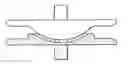
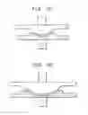
FIG. 1A is an anterior view of an ADR according to the invention;
FIG. 1B is a lateral view of the ADR of FIG. 1;
FIG. 1C is an oblique view of the ADR of FIG. 1;
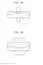
FIG. 2A is a view of the anterior aspect of an alternative embodiment of the ADR;
FIG. 2B is a view of the lateral aspect of an alternative embodiment of the ADR shown in FIG. 2B;
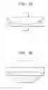
FIG. 3A is a view of the anterior aspect of an alternative, less constrained, embodiment of the saddle-shaped ADR shown in a fully flexed position;
FIG. 3B is a view of the lateral aspect of the embodiment of the ADR shown in FIG. 3A;
FIG. 4A is a view of the lateral aspect of another embodiment of a saddle-shaped ADR;
FIG. 4B is a view of the anterior aspect of the embodiment of the ADR shown in FIG. 4A in a fully flexed position;
FIG. 4C is a view of the anterior aspect of an alternative embodiment;
FIG. 4D is a view of the anterior aspect of the ADR shown in FIG. 4A; and
FIG. 4E is a view of the anterior aspect of the ADR shown in FIG. 4A.
DETAILED DESCRIPTION OF THE INVENTION
FIG. 1A is an anterior view of an ADR according to the invention. FIG. 1B is a lateral view of the ADR of FIG. 1. FIG. 1C is an oblique view of the ADR of FIG. 1.
FIG. 2A is a view of the anterior aspect of an alternative embodiment of the ADR, wherein the articulating surfaces of both components have a flat area centrally from the front to the back of the ADR. FIG. 2B is a view of the lateral aspect of an alternative embodiment of the ADR drawn in FIG. 2B. The flat area of the articulating surfaces courses centrally from side of the DR to the other side. The flat area allows one component to translate slightly on the other component. Alternatively, a curved area with a large radius could replace the flat area.
FIG. 3A is a view of the anterior aspect of an alternative, less constrained, embodiment of the saddle-shaped ADR drawn in a fully flexed position. The less constrained embodiment facilitates spinal flexion, extension, and lateral bending. FIG. 3B is a view of the lateral aspect of the embodiment of the ADR drawn in FIG. 3A.
FIG. 4A is a view of the lateral aspect of another embodiment of a saddle-shaped ADR. The center of rotation for flexion and extension is not necessarily located in the center of the ADR. For example, the center of rotation is preferably located in the posterior half of the ADR. FIG. 4B is a view of the anterior aspect of the embodiment of the ADR drawn in FIG. 4A, drawn in a fully flexed position.
FIG. 4C is a view of the anterior aspect of an alternative embodiment, showing how the radius of curvature of the articulation for lateral bending may be different than the radius of curvature for articulation for flexion and extension. For example, the radius of curvature for the articulation for flexion and extension, as seen in FIG. 4A, may be smaller than the radius of curvature for the articulation for lateral bending, as seen in FIG. 4C. Articulating surfaces with smaller radii, facilitate movement. Thus, the embodiment of the ADR drawn in FIG. 4A flexes and extends more easily than the embodiment of the ADR drawn in FIG. 3A. The ADR is drawn in a fully flexed position.
FIG. 4D is a view of the anterior aspect of the ADR drawn in FIG. 4A. The ADR is drawn in a neutral position. The area of the drawing with diagonal lines represents the articulating surface of the lower ADR component. FIG. 4E is a view of the anterior aspect of the ADR drawn in FIG. 4A, also drawn in a fully extend position.
Claims
1. An artificial disc replacement comprising:
a first component having a first articulating surface and a first vertebral contact surface for engaging a first vertebral body, the first articulating surface including first and second lateral edges and a toroidal region extending from the first lateral edge to the second lateral edge; and
a second component having a second articulating surface opposed to the first articulating surface and a second vertebral contact surface for engaging a second vertebral body, the second articulating surface including third and fourth lateral edges and a toroidal region extending from the third lateral edge to the fourth lateral edge.
Images & Drawings included:

Sources:
- United States Patent and Trademark Office - verify current appl. status at the USPTO↗
Similar patent applications:
- » 20050267582
Spacerless artificial disc replacements - » 20080027548
Spacerless artificial disc replacements - » 20100241233
Spacerless artificial disc replacements - » 20120323332
Spacerless artificial disc replacements - » 20160045329
Spacerless artificial disc replacements - » 20190274839
Spacerless artificial disc replacements
Recent applications in this class:
- » 20250288427 2025-09-18
Artificial Disc Replacement Device - » 20250281302 2025-09-11
INTERVERTEBRAL DISC PROSTHESIS AND REVISION METHOD - » 20250268722 2025-08-28
EXPANDABLE INTERVERTEBRAL IMPLANT - » 20250268721 2025-08-28
LOCKING MECHANISM FOR JOINING BONES AND RELATED METHOD - » 20250213369 2025-07-03
STABILIZING VERTEBRAE WITH ARTICULATING IMPLANTS - » 20250177162 2025-06-05
EXPANDING INTERVERTEBRAL IMPLANTS - » 20250177161 2025-06-05
EXPANDABLE SPINAL IMPLANT - » 20250177160 2025-06-05
STABLENEC STANDALONE INTERBODY - » 20250152376 2025-05-15
EXPANDABLE INTERVERTEBRAL IMPLANT AND INSTRUMENTS FOR INSTALLING THE SAME - » 20250127625 2025-04-24
SPINAL IMPLANT DEVICE FOR MOTION PRESERVATION/DISC STABILIZATION
Recent applications for this Assignee:
- » 20190274839 2019-09-12
Spacerless artificial disc replacements - » 20180116820 2018-05-03
Artificial disc replacements with natural kinematics - » 20180008431 2018-01-11
Intervertebral disc and insertion methods therefor - » 20170156887 2017-06-08
Instrumentation and methods for use in implanting a cervical disc replacement device - » 20170119545 2017-05-04
Artificial disc replacements with natural kinematics - » 20170079808 2017-03-23
Instruments and methods for inserting artificial intervertebral implants - » 20160213494 2016-07-28
Intervertebral disc and insertion methods therefor - » 20160213484 2016-07-28
Intervertebral disc and insertion methods therefor - » 20160151170 2016-06-02
Intervertebral spacer device having recessed notch pairs for manipulation using a surgical tool - » 20160120658 2016-05-05
Cervical disc replacement