SKI WITH TRI-DIMENSIONAL SKI SURFACE
US20140159344A1
2014-06-12
14/124,121
2011-06-07
Abstract:
A ski for mounting a binding on the ski's surface approximately in the middle of the ski or slightly behind the middle, where the ski is provided with inwardly curved edge portions, the ski having greater width at the transition to the front tip than in the middle, and the ski has an upwardly curved front tip. The ski combines features from skis with a very special and characteristic three-dimensional geometry in the actual sliding surface, and a special design of the tip (possibly also in a rear tip where this is relevant), where the tip's secondary sole surfaces (3, 4) are twisted upwards relative to a central reference surface (1, 2), with the result that the ski's tip succeeds in pressing more snow under the ski when running in loose snow and slush, and the invention thereby provides a ski which both glides better in loose snow as well as retaining all the favourable dynamic properties which exist in the described three-dimensional design of the actual sliding surface on the ski.
Assignee:
- HiTurn AS 9 🇳🇴 Raufoss, Norway
Interested in similar patents?
Get notified when new applications in this technology area are published.
Classification:
A63C5/0405 » CPC main
Skis or snowboards; Structure of the surface thereof Shape thereof when projected on a plane, e.g. sidecut, camber, rocker
A63C5/04 IPC
Skis or snowboards Structure of the surface thereof
Description
The present invention relates to a ski, where the ski is designed to have a binding mounted approximately in the middle of the ski, when viewed in the ski's longitudinal direction, or slightly behind the middle. The ski is provided with inwardly curved steel edges (edge portions), the ski having a greater width at the transition to the tip than under the binding. The ski has upwardly curved tips at the front and the rear, where the tips may well be approximately of the same size, but the rear tip is often more modest, or merely a slight upward curve of the sole with a truncated end at the back, which is also referred to here as the rear tip.
These days a ski is normally designed with a flat sole surface between the front and rear tips of the ski, but skis are also known with a split sole surface. The ski according to the present invention is based on a three-dimensional geometry of the ski's sliding surface, as is disclosed in international patent application WO 95/21662, amongst others. The ski described in this patent application is provided with a sole where the sliding surface in the sole is not flat, but in principle divided into three sliding surfaces over the ski's longitudinal direction, where this design has been shown to give the skis advantageous dynamic properties. In principle, these skis have an increasing angle between a central sliding surface in the ski's sole, here called the primary sole surface, and lateral sliding surfaces arranged on each side of the primary sole surface, here called secondary sole surfaces, where the secondary sole surfaces extend along the ski's steel edges up to the transition to the tip. The geometry is characterised by an increase in the angle between the different sole surfaces towards the transition to the tip, and possibly towards the rear tip. However, all of the known versions of skis with this geometry in the sliding surface have phased out the angle between the primary or central sole surface and the lateral sole surfaces from the transition to the ski's tip and forward in this tip, and the same backwards in the rear tip to the extent that the ski has a substantial rear tip with this functionality.
Testing of new prototypes of skis has demonstrated that in loose snow and other soft, loose surfaces it is advantageous to have the tripartite sliding surface, but particularly advantageous if the angular difference between the different sole surfaces not only continues into the tip, but the angle between the extension of the different sole surfaces in the tip increases substantially over a length of the tip. As indicated above, however, the known design of a ski with a tripartite sliding surface will phase out the angular difference between the central sliding surface (the primary sole surface) and the lateral sliding surfaces or the secondary sole surfaces on each side approximately from the transition to the tip and further forward in the tip. If on the other hand the angle between the central sliding surface or the primary sole surface and the lateral sliding surfaces or the secondary sole surfaces on each side is increased forward in the tip, possibly doing the same backwards in the rear tip, where this is relevant, great benefits were achieved in loose snow in our tests. The increase in the angle starts approximately in the transition between the flat sliding surface of the sole and the tip, but it may also start a few cm further in towards the middle of the ski (i.e. in towards the bindings), or slightly further out in the tip. The increase in angle is generally accelerated approximately from the transition to the tip and a few cm forwards. With this type of functionality the aim is to achieve a tip which during turning is even better at pressing snow under the ski, thereby giving the ski better glide over a loose surface. The positive effect is achieved when the ski is run on its edge on a loose surface, when the tip lies several degrees flatter on the snow on a ski according to the present invention than for example the existing skis with a tripartite sliding surface according to WO 95/21662. This means that during turning the tip with accelerated twisting of the tip's secondary sole surfaces presses more snow under the ski than corresponding skis with a tripartite sole in the sliding surface and phase-out of the difference between the sole surfaces in the tip.
When the ski glides better on the snow during turning, this makes it go faster. This is a general effect of the present invention. However, the greatest benefits are during freestyle skiing down difficult mountain sides. After landing from a difficult jump, the skier must have skis that quickly come up out of the snow, while at the same time being able to initiate a turn, since the skier often has to manoeuvre himself away from dangerous obstacles right in front of him. The design of the tip in combination with the tripartite sliding surface together provide the best maneuverability in such a situation.
There are special types of snow where accelerated twisting of the lateral sole surfaces in the tip is particularly advantageous. This is during freestyle skiing in deep snow when a thin, non-bearing crust layer has formed on the snow. In this situation normal skis have an unfortunate tendency to cut down into the crust, thereby causing braking and “quivering” in the ski. By means of the new design of the ski according to the present invention, i.e. the new type of tip combined with a dynamic three-dimensional sliding surface, however, the sole surfaces will lie slightly flatter against the snow during turning, thereby providing better lift and avoiding many of the problems experienced by ordinary, flat skis in conditions of this kind.
DEFINITIONS
The primary sole surface 1 is the central sliding surface which forms a part of the ski's total sliding surface. When the ski (apart from the tip) is pressed completely flat against the surface so that the longitudinal camber is not shown, this is the part of the ski which touches the surface. If the transition (the angle) between the primary sole surface and the secondary sole surfaces 3 is diffuse because the transition, when viewed in cross section, is gradual via a slight rounding of the different sole surfaces, in such cases portions which in cross section are located up to 0.5 mm above the ground when the longitudinal camber is depressed are also defined as belonging to the primary sole surface, while portions which without longitudinal camber are located more than 0.5 mm above the surface belong to the sliding surface's secondary sole surfaces, when viewed in cross section. Here the lines J, K, L, M in the figures mark the transition between the sole surfaces according to this definition.
The tip's primary sole surface 2 is the extension of the central sliding surface forwards in the tip, where this sole surface here follows the upward curve in the tip, and possibly correspondingly in the rear tip. To the extent that the tip essentially consists of a left and a right secondary sliding surface, the “keel” between the left and right secondary surfaces will define the tip's primary sole surface.
The secondary sole surfaces 3 are located in the sliding surface between the primary sole surface 1 and steel edges 5 arranged in the ski's longitudinal direction. When the ski (apart from the tip) is pressed completely flat against the surface so that the ski's camber in the longitudinal direction is not shown, the secondary sole surfaces 3 are twisted substantially upwards relative to the primary sole surface towards the transition between the primary sole surface and the secondary sole surfaces and the tip or tips provided in the ski, thereby ensuring that the steel edges in the lateral sliding surfaces or the secondary sole surfaces are essentially raised higher over the surface towards the transition to the tip.
The tip's secondary sole surfaces 4 are located between the tip's first sole surface and the steel edges. We see a cross sectional view of the uplift of the steel edges relative to the tip's primary sole surface from the transition (C, D) to the tip and a few centimeters forward, and possibly correspondingly from the transition (W, X) to the rear tip and a few cm backwards if this is relevant.
The ski's edges are called steel edges 5 here since iron/steel is the most commonly used material for edges. In principle, however, any material whatever can be used which is hard enough to give the desired functionality in the lateral edge defining the sole.
The surface 6 is always shown flat and represents the ground or the snow.
The following alphabetic designations are employed:
-
- A. At the front of the tip
- B. Cross section approximately in the centre of the tip
- C. The transition between the primary sole surface 1 and the tip's primary sole surface 2
- D. Transition between the secondary sole surfaces 3 and the tip's secondary sole surfaces 4
- E. Cross section between D and F
- F. The secondary sole surfaces 3 start here. This start does not need to be the same on the right and left sides of the ski, but is illustrated symmetrically here.
- G. The ski's narrowest point
- j. Transition line between primary sole surface 1, 2 and secondary sole surface 3, 4 on the left side in front viewed from below
- k. Transition line between primary sole surface 1, 2 and secondary sole surface 3, 4 on the left side in front
- l. Transition line between primary sole surface 1, 2 and secondary sole surface 3, 4 on the left side behind viewed from below
- m. Transition line between primary sole surface 1, 2 and secondary sole surface 3, 4 on the right side at the rear
- U. The secondary sole surfaces 3 start here if geometry with split raised secondary sliding surfaces is employed on the rear part.
- V. Cross section between U and W
- W. Transition between the secondary sole surfaces 3 and the tip's secondary sole surfaces 4
- X. The transition between the primary sole surface 1 and the rear tip's primary sole surface 2
- Y. Cross section approximately in the middle of the tip
- Z. The rearmost part of the ski.
The invention consists in a ski which basically has a tripartite sole in the sliding surface (three-dimensional geometry). Thus the ski has a substantially flat central sliding surface, the primary sole surface 1, which is located approximately halfway between the steel edges 5, and then there are two lateral sliding surfaces, the secondary sole surfaces 3, between the primary sole surface and the steel edges 5 on each side thereof, where these secondary sole surfaces form a substantially increasing angle with the primary sole surface 1 when starting directly below the bindings and moving towards each of the ends and the transitions (C) and (X). In the figures the secondary sliding surfaces start at F, and a cautious increase can be seen in the uplift in the steel edges from the cross section in F to E and on to D. From the cross section in D the uplift in the steel edges increases more rapidly up to the cross section in B. Whether the uplift increases or decreases from B and onwards is more a matter of choice or taste. From B towards A the tip is so far above the snow that it no longer is of such great practical importance.
The ski with the tripartite sliding surface may well be completely flat from steel edge to steel edge in the middle where the bindings are located, but at any rate over more than 10% of the ski's sliding surface, when viewed in the longitudinal direction, the ski should be provided with secondary sliding surfaces, and preferably over at least 15%. At the transition (D) to the tip, the angle between the primary sole surface 1 and the secondary sole surfaces 3 has increased to at least 1 degree, preferably to at least 2 degrees, and most preferred to more than 3 degrees at the transition (D) between sliding surface and tip for the secondary sole surfaces. The uplift in the steel edge 5 relative to the primary sole surface 1 depends on the relative angle between the primary sole surface 1 and the secondary sole surface 3 as well as the width of the ski and the width of the secondary sole surfaces. Thus, for example, a 3 degree angle between the sole surfaces in cross section may correspond to anything from 1 mm to over 4 mm uplift in the steel edge.
The angle between the tip's secondary lateral surfaces 4 and the tip's primary sole surface 1 increases preferably by at least 1 degree, preferably by at least 2 degrees from D to B. Thereafter it is optional whether this angle is permitted to return to zero from B right up to the front of the tip, or whether the angle is maintained or increased all the way forward. This degree of freedom is due to the fact that the foremost part of the tip is of relatively little importance.
Particularly if the sole surfaces are slightly rounded in cross section, instead of angles between the respective sole surfaces, the uplift may be viewed measured in mm for the steel edge 5 relative to the tip's primary sole surface 2, but here too the uplift varies with the width of the tip's secondary sole surfaces, with the result that the same angle can give substantial differences in mm uplift where 5 degrees uplift in the steel edge 5 in the tip can give anything from 1.5 mm to 7 mm uplift relative to the tip's primary sole surface 2 in the tip. The uplift in the steel edge 5 relative to the tip's primary sole surface 2 will increase by more than 0.5 mm from the transition (D) between sliding surface and tip until the uplift in the steel edge 5 relative to the tip's primary sole surface 2 has reached its maximum. The uplift preferably increases by at least 1 mm, and preferably more than 1.5 mm. Thereafter it is optional whether the uplift is permitted to return to zero right up to the front of the tip, or whether the uplift is maintained or increased all the way forward.
In the area round the transition (C, D) to the tip (and possibly (W, X) to the rear tip), therefore, an increase in the uplift in the steel edges begins to be allowed, and the uplift normally increases more rapidly outwards in the tip than it did along the ordinary sliding surfaces 1, 3. This results in an increase in the uplift in the steel edges forwards from C to B in the tip, viewed in a section across the tip. When the tip narrows, however, this uplift will generally decline. If connected steel edges 5 are employed in the tip and they are without a break, it is necessary for the steel edges to be continuous so that the uplift measured in mm reaches zero at the front of the tip.
The invention's special functionality for the tip is of great importance for the front tip, and it is therefore most important to also employ this functionality in the rear tip when the ski is designed for landing and skiing backwards from time to time.
On this basis, therefore, it is an object of the present invention to provide a ski with improved dynamic. This is achieved with a ski which is characterised by the features which will be apparent in the patent claims.
From WO 95/21662 a pair of Alpine skis is known with a flat sliding surface and lateral sliding surfaces, where the sole's edge is provided with an approximately continuous concave inward curve in the steel edge along the ski between a first transition line which defines the transition from a tip portion to a sliding portion and a second transition line which defines the transition from sliding portion to a rear portion. The lower lateral edge (the steel edge) describes an approximately continuous curve between the transition lines to the tips. The sole on both sides of the first sliding surface comprises additional sliding surfaces extending upwards from the edge of the first sliding surface to the lower lateral edges on the ski with an upward curve. The upward curve in the lower lateral edge of the additional sliding surfaces increases substantially with the ski's increasing width in the direction of the two transition lines towards the tips.
An Alpine ski as described in WO 95/21662 has proved to be very well-suited to Alpine events and the angled sliding surfaces, which with only a relatively slight edging of the ski can be pressed into contact with the surface, provide improved turning technique and surface grip.
The ski according to the present invention differs from known ski designs in the proposition, amongst other things, that the tip's secondary sole surfaces 4 which constitute the dynamic difference, are located precisely in the tips outside the ski's ordinary sliding surfaces 1, 3 (the primary sole surface and the secondary sole surfaces). WO 95/21662 describes a solution for a dynamically optimal geometry in the sliding surface, while here we are looking at an optimal sliding surface of this kind combined with an optimal design of the tip.
The invention will now be described in greater detail by means of embodiments which are illustrated in the drawings. All the figures depict skis according to the present invention specially designed for improving lift during turning in combination with a dynamic geometry in the sliding surface. In each figure the ski or details thereof is shown from various sides:
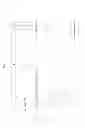
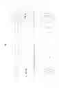
FIG. 1 i) The ski viewed from the underside shows the sole of the ski with dotted lines illustrating where there are smooth transitions between various portions
-
- ii) The ski viewed from the side. The uplift in the steel edge is slightly exaggerated in order to illustrate the point
- iii) Cross section of the ski, slightly enlarged relative to i)
- iv) On some skis the angle between the tip's sole surfaces is continued right up to the tip, and then the ski is viewed from in front in order to illustrate this variant.
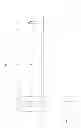
FIG. 2 illustrates a second embodiment of the ski according to FIG. 1.
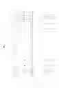
FIG. 3 illustrates a further embodiment of the ski according to FIG. 1, and
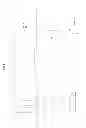
FIGS. 4 to 8 illustrate further details and/or embodiments of the ski according to FIG. 1.
FIG. 1 illustrates a ski according to the present invention where the ski is provided with relatively wide secondary lateral surfaces 3 with a gradually increasing upward curve in steel edge 5 up towards a transition D to a tip of the ski. The tip's central sole surface 2 is curved upwards from a transition C. An angle between primary sole surface 1, 2 (sole surface in ski and tip) and the tip's secondary sole surfaces 4 increases from the transition to the transition D and forwards in the tip to a cross section B between the cross sections C and A. The increase in the angle between the primary sole surface 1, 2 and the secondary sole surfaces 3, 4 typically occurs more rapidly from the transitions D to B than from the transitions F to D viewed per unit of length. This causes the uplift of the steel edge 5 measured in mm to also increase more rapidly from the transitions D to B than from the transitions F to D. From the transition B and forwards the angle between the primary sole surface 1, 2 and the secondary sole surfaces 3, 4 is phased out until it is zero at the front of the tip. This ski is partly twin tip and has a slightly more modest rear tip than front tip, and here a tripartite sliding surface is illustrated on the ski's rear part without any special functionality being implemented in the rear tip.
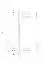
FIG. 2 illustrates approximately the same geometry of the ski as illustrated FIG. 1, but here the areas with secondary sole surfaces 3, 4 are of a slightly narrower design. The most important difference is that extra functionality is introduced with increasing uplift in the rear tip all the way back to the steel edge 5. In the sliding surface the ski has secondary sole surfaces 3 with a gradually increasing upward curve in the steel edge 5 up to the transition C, D to the tip. The tip's primary sole surface 2 is curved upwardly from the transition C. As shown here, the extra uplift of the tip's secondary sole surfaces 4 starts in the same cross section C, D as the tip begins to curve upwards. The angle between the tip's primary sole surface 2 and the tip's secondary sole surfaces 4 increases from the transition to the transition C, D and forwards in the tip to a transition B approximately halfway to a point A. From the transition B and forwards, the angle between the sole surfaces 2, 4 is kept constant, with the result that viewed from in front iv) the tip appears with two small angles, which is illustrated in a somewhat exaggerated way here. The same applies to the rear tip. The uplift of the steel edge 5 viewed in cross section relative to the sole surfaces 1, 2 measured in mm increases more rapidly from transition D to B than from transition F to D. From transition B and forwards the uplift measured in mm approaches zero even though the angle between the sole surfaces 2, 4 is kept constant.
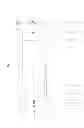
FIG. 3 illustrates a further embodiment of a ski according to the present invention, where the ski is depicted with a truncated rear tip. The uplift in the steel edge 5 starts in transition F and increases cautiously up to transition D, from where the uplift is accelerated up to transition B. From transition B and forwards an angle (break) is maintained between the tip's primary sole surface 2 and the tip's secondary sole surfaces 4, but here the secondary sole surfaces 4 round the tip are continued right up to point A, thereby preventing any breaks in the steel edge 5 at any point in the tip. Left lateral sliding surface (secondary sole surface) 3 is wider than right lateral sliding surface (secondary sole surface) 3 viewed from below, in order to illustrate a possible asymmetrical solution. This asymmetry is also included in the tips. The accelerated uplift of the lateral sole surface already begins here in transition D, even though the tip in the central area begins in transition C. The uplift measured in mm in the steel edges 5 relative to the primary sole surface 1, 2 increases more rapidly from transition D to B than from transition F to D. On the ski's rear part the sliding surface is also divided into three, but since there is only a small, blunt rear tip, the increase in the uplift is terminated in the transition W, X to the rear tip, and from there, for example, a constant angle is maintained between the rear tip's sole surfaces 2, 4 all the way to transition Z.
FIG. 4 illustrates a so-called twin tip ski. A version is shown where the tip's primary sole surface 2 is reduced to a kind of keel forwards in the tip. The front and rear have been given a slightly different design in order to illustrate different variants, and there is no functional reason for one variant being at the front and the other at the rear. The uplift in the steel edges 5 is viewed in cross section relative to this primary sole surface or “keel” 2. The uplift measured in mm in the steel edges 5 relative to the lines j, k (m, l) increases more rapidly from the transition D (W) to B (Y) than from transition F (U) to D (W).
FIG. 5 i) illustrates a twin tip ski, where this twin tip ski has a primary sole surface 1 defined by the flat portion under the bindings and the portion of the ski touching the surface when the ski is pressed against the surface, thereby causing the camber to be pressed flat and the whole primary sole surface 1 to touch the ground. iii) Here the transition between primary sole surface 1 and the second sole surfaces 3 is diffuse (not so clear), since the transition between the sole surfaces 1, 3 is slow via a slight rounding, when viewed in cross section. In cases of diffuse transitions, portions which in cross section are located up to 0.5 mm over the ground when the longitudinal camber is depressed are also defined as belonging to or part of the primary sole surface 1, while portions located more than 0.5 mm over the surface belong to or are a part of the sliding surface's secondary sole surfaces 3. The lines j, k, l, m here mark the transition between the sole surfaces according to this definition. The slight curvature viewed in cross section in the primary sole surface 1 continues into the tip's primary sole surface 2. The dynamic in the ski is improved if the portions nearest the steel edges 5 are as flat as possible, so here a cross section of the lateral sole surfaces 3, 4 is illustrated as straight the last 2-4 cm nearest the steel edges 5, but a slight curvature does not provide such a great difference dynamically. The uplift measured in mm in the steel edges 5 is measured relative to the middle of the primary sole surface 1 if it is slightly curved. The uplift in the steel edges increases more rapidly from transition D to B than from transition F to D per unit of length. In order to better illustrate the curvature in the surfaces, the angles in the cross sections are exaggerated in the order of 2-4 times what we consider to be optimal from the dynamic point of view. Here too differences are shown at the front and rear of the ski in order to illustrate different design variants.
FIG. 6 illustrates a typical ski with a truncated rear tip, and a possible design of the sliding surface where there are only secondary sole surfaces on the ski's front portion. The uplift in the steel edges increases more rapidly from transition D to B than from transition F to D per unit of length.
FIG. 7 illustrates a twin tip ski with special raised edges in the middle in order to be able to slide sideways on rails and boxes (not shown) without catching the steel edges 5 so easily in rough patches in the rail or box. The uplift in the steel edges 5 in the middle is considered to be an extra functionality which has no bearing on the invention. According to the present invention the ski is provided with a tripartite sliding surface at the front and also the rear. The tip's primary sole surface 2 is reduced successively forwards from transition D, thereby splitting the front part of the tip's sole surface into two parts in the right and left secondary sole surface 4 towards the point A. In order to illustrate possibilities for variation, a slightly different version of the ski's rear part is shown.
FIG. 8 i) illustrates a ski where the flat sliding surface is divided into a right and left secondary sole surface 3 without retaining any flat sliding surface (primary sole surface) 1 between them, with the result that the flat sliding surface (primary sole surface) 1 is composed of a keel. From transition C, D the upward curve in the steel edge 5 is further increased relative to the keel. Here we have chosen to continue the angular increase between the secondary lateral surfaces right up to the point A. iv). This is seen in a characteristic break in the middle of the tip when viewed from in front.
Every variant which is illustrated on a sufficiently large tip can be used on all types of ski, whether it be a ski of the twin tip type, twin tip with a small rear tip or a ski with an ordinary tip and truncated rear tip.
In the sliding surface the secondary sole surfaces 3 will substantially twist upwards relative to the primary sole surface 1 and this twisting will increase at the transition D and some distance forwards in the tip to transition B.
Five tables are now set up illustrating skis of different lengths according to the present invention, and with examples of the uplift in the steel edges 5 relative to primary sole surface 1, 2, when viewed in cross section. Uplift and geometry are deliberately varied in order to illustrate different possibilities within the scope of the invention.
| TABLE 1 |
| One possible example of a directional ski 1650 mm long according to invention |
| Total width | Total width | Length | Length | Sidecut |
| at C (mm) | at G (mm) | C-G (mm) | G-X (mm) | radius. |
| 114.0 | 65 | 780 | 720 | 12429 |
| Width of | Width of | Uplift of | Calculated Angle | ||||
| Distance | the primary | each of the | steel edge(5) | Steps of | between primary | ||
| from | Total width | sole (1, 2) | secondary(3, 4) | relative primary | steel edge | and | |
| the tip | of the ski | surface | sole surfaces | sole(1, 2) | uplift | Cross | secondary sole |
| (mm) | (mm) | (mm) | (mm) | (mm) | (mm) | section | (degrees) |
| 0 | 0 | 0 | 0 | 0.00 | 0.00 | A | |
| 30 | 85 | 28 | 28 | 1.00 | −1.00 | 2.02 | |
| 60 | 103 | 34 | 34 | 2.50 | −1.50 | 4.18 | |
| 90 | 111 | 37 | 37 | 3.50 | −1.00 | B | 5.43 |
| 120 | 114 | 38 | 38 | 2.50 | 1.00 | C | 3.77 |
| 150 | 110 | 37 | 37 | 1.90 | 0.60 | D | 2.97 |
| 180 | 107 | 36 | 36 | 1.73 | 0.18 | 2.78 | |
| 210 | 103 | 34 | 34 | 1.56 | 0.17 | 2.59 | |
| 240 | 100 | 33 | 33 | 1.39 | 0.16 | 2.40 | |
| 270 | 97 | 32 | 32 | 1.24 | 0.16 | 2.20 | |
| 300 | 94 | 31 | 31 | 1.09 | 0.15 | 1.99 | |
| 330 | 91 | 30 | 30 | 0.95 | 0.14 | E | 1.79 |
| 360 | 88 | 29 | 29 | 0.81 | 0.13 | 1.58 | |
| 390 | 86 | 29 | 29 | 0.69 | 0.13 | 1.37 | |
| 420 | 84 | 28 | 28 | 0.57 | 0.12 | 1.17 | |
| 450 | 81 | 27 | 27 | 0.45 | 0.11 | 0.96 | |
| 480 | 79 | 26 | 26 | 0.35 | 0.11 | 0.76 | |
| 510 | 77 | 26 | 26 | 0.25 | 0.10 | 0.56 | |
| 540 | 75 | 25 | 25 | 0.16 | 0.09 | 0.37 | |
| 570 | 74 | 25 | 25 | 0.08 | 0.08 | 0.18 | |
| 600 | 72 | 72 | 0 | 0 | 0.08 | F | |
| 630 | 71 | 71 | 0 | 0 | |||
| 660 | 70 | 70 | 0 | 0 | If each part | ||
| 690 | 69 | 69 | 0 | 0 | of the cross | ||
| 720 | 68 | 68 | 0 | 0 | section of | ||
| 750 | 67 | 67 | 0 | 0 | the ski's sole | ||
| 780 | 66 | 66 | 0 | 0 | were totally | ||
| 810 | 66 | 66 | 0 | 0 | straight, then | ||
| 840 | 65 | 65 | 0 | 0 | the angle | ||
| 870 | 65 | 65 | 0 | 0 | between | ||
| 900 | 65 | 65 | 0 | 0 | G | the primary | |
| 930 | 65 | 65 | 0 | 0 | sole (1, 2) | ||
| 960 | 65 | 65 | 0 | 0 | and the | ||
| 990 | 66 | 66 | 0 | 0 | secondary | ||
| 1020 | 66 | 66 | 0 | 0 | sole (3, 4) | ||
| 1050 | 67 | 67 | 0 | 0 | would | ||
| 1080 | 68 | 68 | 0 | 0 | have these | ||
| 1110 | 69 | 69 | 0 | 0 | theoretical | ||
| 1140 | 70 | 70 | 0 | 0 | figures | ||
| 1170 | 71 | 71 | 0 | 0 | |||
| 1200 | 72 | 72 | 0 | 0 | U | ||
| 1230 | 74 | 25 | 25 | 0.08 | −0.08 | 0.18 | |
| 1260 | 75 | 25 | 25 | 0.16 | −0.08 | 0.37 | |
| 1290 | 77 | 26 | 26 | 0.25 | −0.09 | 0.56 | |
| 1320 | 79 | 26 | 26 | 0.35 | −0.10 | 0.76 | |
| 1350 | 81 | 27 | 27 | 0.45 | −0.11 | 0.96 | |
| 1380 | 84 | 28 | 28 | 0.57 | −0.11 | 1.17 | |
| 1410 | 86 | 29 | 29 | 0.69 | −0.12 | 1.37 | |
| 1440 | 88 | 29 | 29 | 0.81 | −0.13 | V | 1.58 |
| 1470 | 91 | 30 | 30 | 0.95 | −0.13 | 1.79 | |
| 1500 | 94 | 31 | 31 | 1.09 | −0.14 | 1.99 | |
| 1530 | 97 | 32 | 32 | 1.24 | −0.15 | 2.20 | |
| 1560 | 100 | 33 | 33 | 1.39 | −0.16 | 2.40 | |
| 1590 | 103 | 34 | 34 | 1.56 | −0.16 | 2.59 | |
| 1620 | 107 | 36 | 36 | 1.73 | −0.17 | X | 2.78 |
| 1650 | 100 | 33 | 33 | 1.90 | −0.17 | Z | 3.27 |
| This ski has normal uplift from F to D, and then the uplift increases from D to B as described by the invention | |||||||
| This ski has no special uplift at rear tip, it carries the uplift backwards with no substantial increase from X to Z |
| TABLE 2 |
| One possible example of a twin tip ski 1710 mm long according to invention |
| Total width | Total width | Length | Length | Sidecut |
| at C (mm) | at G (mm) | C-G (mm) | G-X (mm) | radius. |
| 110.0 | 77 | 750 | 690 | 17054 |
| Width of | Width of | Uplift of | Calculated Angle | ||||
| Distance | the primary | each of the | steel edge(5) | Steps of | between primary | ||
| from | Total width | sole (1, 2) | secondary(3, 4) | relative primary | steel edge | and | |
| the tip | of the ski | surface | sole surfaces | sole(1, 2) | uplift | Cross | secondary sole |
| (mm) | (mm) | (mm) | (mm) | (mm) | (mm) | section | (degrees) |
| 0 | 0.0 | 0 | 0.0 | 0.00 | 0.00 | A | |
| 30 | 85.0 | 5 | 40.0 | 2.00 | −2.00 | 2.87 | |
| 60 | 100.0 | 10 | 45.0 | 4.00 | −2.00 | 5.10 | |
| 90 | 107.0 | 15 | 46.0 | 5.00 | −1.00 | B | 6.24 |
| 120 | 110.0 | 20 | 45.0 | 4.80 | 0.20 | 6.13 | |
| 150 | 110.0 | 25 | 42.5 | 3.80 | 1.00 | C | 5.13 |
| 180 | 107.4 | 30 | 38.7 | 2.90 | 0.90 | 4.30 | |
| 210 | 104.9 | 35 | 35.0 | 2.28 | 0.62 | D | 3.75 |
| 240 | 102.6 | 35 | 33.8 | 2.09 | 0.19 | 3.56 | |
| 270 | 100.3 | 35 | 32.6 | 1.91 | 0.18 | 3.36 | |
| 300 | 98.1 | 35 | 31.6 | 1.74 | 0.17 | 3.16 | |
| 330 | 96.1 | 35 | 30.5 | 1.57 | 0.16 | 2.96 | |
| 360 | 94.1 | 35 | 29.6 | 1.42 | 0.16 | 2.75 | |
| 390 | 92.3 | 35 | 28.6 | 1.27 | 0.15 | 2.54 | |
| 420 | 90.5 | 35 | 27.8 | 1.13 | 0.14 | 2.34 | |
| 450 | 88.9 | 35 | 26.9 | 1.00 | 0.13 | E | 2.13 |
| 480 | 87.3 | 35 | 26.2 | 0.88 | 0.12 | 1.92 | |
| 510 | 85.9 | 35 | 25.5 | 0.76 | 0.11 | 1.72 | |
| 540 | 84.6 | 35 | 24.8 | 0.66 | 0.11 | 1.52 | |
| 570 | 83.4 | 35 | 24.2 | 0.56 | 0.10 | If each part | |
| 600 | 82.3 | 35 | 23.6 | 0.47 | 0.09 | of the cross | |
| 630 | 81.3 | 35 | 23.1 | 0.39 | 0.08 | section of | |
| 660 | 80.4 | 35 | 22.7 | 0.32 | 0.07 | the ski's sole | |
| 690 | 79.6 | 35 | 22.3 | 0.26 | 0.06 | were totally | |
| 720 | 78.9 | 35 | 21.9 | 0.20 | 0.05 | straight, then | |
| 750 | 78.3 | 35 | 21.7 | 0.16 | 0.05 | the angle | |
| 780 | 77.8 | 35 | 21.4 | 0.12 | 0.04 | between | |
| 810 | 77.5 | 35 | 21.2 | 0.09 | 0.03 | the primary | |
| 840 | 77.2 | 35 | 21.1 | 0.07 | 0.02 | sole (1, 2) | |
| 870 | 77.1 | 35 | 21.0 | 0.05 | 0.01 | and the | |
| 900 | 77.0 | 35 | 21.0 | 0.05 | 0.00 | F, G, U | secondary |
| 930 | 77.1 | 35 | 21.0 | 0.05 | 0.00 | sole (3, 4) | |
| 960 | 77.2 | 35 | 21.1 | 0.07 | −0.01 | would | |
| 990 | 77.5 | 35 | 21.2 | 0.09 | −0.02 | have these | |
| 1020 | 77.8 | 35 | 21.4 | 0.12 | −0.03 | theoretical | |
| 1050 | 78.3 | 35 | 21.7 | 0.16 | −0.04 | figures | |
| 1080 | 78.9 | 35 | 21.9 | 0.20 | −0.05 | 0.53 | |
| 1110 | 79.6 | 35 | 22.3 | 0.26 | −0.05 | 0.66 | |
| 1140 | 80.4 | 35 | 22.7 | 0.32 | −0.06 | 0.81 | |
| 1170 | 81.3 | 35 | 23.1 | 0.39 | −0.07 | 0.97 | |
| 1200 | 82.3 | 35 | 23.6 | 0.47 | −0.08 | 1.15 | |
| 1230 | 83.4 | 35 | 24.2 | 0.56 | −0.09 | 1.33 | |
| 1260 | 84.6 | 35 | 24.8 | 0.66 | −0.10 | 1.52 | |
| 1290 | 85.9 | 35 | 25.5 | 0.76 | −0.11 | V | 1.72 |
| 1320 | 87.3 | 35 | 26.2 | 0.88 | −0.11 | 1.92 | |
| 1350 | 88.9 | 35 | 26.9 | 1.00 | −0.12 | 2.13 | |
| 1380 | 90.5 | 35 | 27.8 | 1.13 | −0.13 | 2.34 | |
| 1410 | 92.3 | 35 | 28.6 | 1.27 | −0.14 | 2.54 | |
| 1440 | 94.1 | 35 | 29.6 | 1.42 | −0.15 | 2.75 | |
| 1470 | 96.1 | 35 | 30.5 | 1.57 | −0.16 | 2.96 | |
| 1500 | 98.1 | 35 | 31.6 | 1.74 | −0.16 | 3.16 | |
| 1530 | 100.3 | 30 | 35.1 | 1.91 | −0.17 | W | 3.12 |
| 1560 | 102.6 | 25 | 38.8 | 2.80 | −0.89 | 4.14 | |
| 1590 | 104.9 | 20 | 42.5 | 3.50 | −0.70 | X | 4.73 |
| 1620 | 105.0 | 15 | 45.0 | 4.00 | −0.50 | Y | 5.10 |
| 1650 | 100.0 | 10 | 45.0 | 3.00 | 1.00 | 3.82 | |
| 1680 | 80.0 | 5 | 37.5 | 1.50 | 1.50 | 2.29 | |
| 1710 | 0.0 | 0 | 0.0 | 0.00 | 1.50 | Z | |
| This ski has uplifted steeledges along the entire sole, from G, F, U to D and W, and then the uplift increases from I and from W to Y as described by the invention |
| TABLE 3 |
| One possible example of a twin tip ski 1740 mm long according to invention |
| Total width | Total width | Length | Length | Sidecut |
| at C (mm) | at G (mm) | C-G (mm) | G-X (mm) | radius. |
| 115.0 | 85 | 720 | 720 | 17288 |
| Width of | Width of | Uplift of | Calculated Angle | ||||
| Distance | the primary | each of the | steel edge(5) | Steps of | between primary | ||
| from | Total width | sole (1, 2) | secondary(3, 4) | relative primary | steel edge | and | |
| the tip | of the ski | surface | sole surfaces | sole(1, 2) | uplift | Cross | secondary sole |
| (mm) | (mm) | (mm) | (mm) | (mm) | (mm) | section | (degrees) |
| 0 | 0.0 | 0 | 0.0 | 0.00 | 0.00 | A | |
| 30 | 85.0 | 3 | 41.0 | 2.00 | −2.00 | 2.80 | |
| 60 | 100.0 | 6 | 47.0 | 4.00 | −2.00 | 4.88 | |
| 90 | 108.0 | 9 | 49.5 | 4.50 | −0.50 | B | 5.22 |
| 120 | 113.0 | 12 | 50.5 | 4.20 | 0.30 | 4.77 | |
| 150 | 115.0 | 15 | 50.0 | 3.70 | 0.50 | C | 4.25 |
| 180 | 112.6 | 18 | 47.3 | 3.20 | 0.50 | 3.88 | |
| 210 | 110.2 | 21 | 44.6 | 2.80 | 0.40 | D | 3.60 |
| 240 | 108.0 | 24 | 42.0 | 2.49 | 0.31 | 3.40 | |
| 270 | 105.8 | 27 | 39.4 | 2.19 | 0.30 | 3.18 | |
| 300 | 103.8 | 30 | 36.9 | 1.90 | 0.28 | 2.96 | |
| 330 | 101.9 | 33 | 34.4 | 1.63 | 0.27 | 2.72 | |
| 360 | 100.0 | 36 | 32.0 | 1.38 | 0.26 | E | 2.47 |
| 390 | 98.3 | 39 | 29.7 | 1.14 | 0.24 | 2.20 | |
| 420 | 96.7 | 42 | 27.4 | 0.91 | 0.23 | 1.91 | |
| 450 | 95.2 | 45 | 25.1 | 0.70 | 0.21 | 1.60 | |
| 480 | 93.8 | 48 | 22.9 | 0.50 | 0.20 | 1.26 | |
| 510 | 92.5 | 51 | 20.7 | 0.32 | 0.18 | 0.88 | |
| 540 | 91.3 | 54 | 18.6 | 0.15 | 0.17 | 0.47 | |
| 570 | 90.2 | 90 | 0.0 | 0.00 | 0.15 | F | 0.00 |
| 600 | 89.2 | 89 | 0.0 | 0.00 | 0.00 | ||
| 630 | 88.3 | 88 | 0.0 | 0.00 | If each part | ||
| 660 | 87.6 | 88 | 0.0 | 0.00 | of the cross | ||
| 690 | 86.9 | 87 | 0.0 | 0.00 | section of | ||
| 720 | 86.3 | 86 | 0.0 | 0.00 | the ski's sole | ||
| 750 | 85.8 | 86 | 0.0 | 0.00 | were totally | ||
| 780 | 85.5 | 85 | 0.0 | 0.00 | straight, then | ||
| 810 | 85.2 | 85 | 0.0 | 0.00 | the angle | ||
| 840 | 85.1 | 85 | 0.0 | 0.00 | between | ||
| 870 | 85.0 | 85 | 0.0 | 0.00 | G | the primary | |
| 900 | 85.1 | 85 | 0.0 | 0.00 | sole (1, 2) | ||
| 930 | 85.2 | 85 | 0.0 | 0.00 | and the | ||
| 960 | 85.5 | 85 | 0.0 | 0.00 | secondary | ||
| 990 | 85.8 | 86 | 0.0 | 0.00 | sole (3, 4) | ||
| 1020 | 86.3 | 86 | 0.0 | 0.00 | would | ||
| 1050 | 86.9 | 87 | 0.0 | 0.00 | have these | ||
| 1080 | 87.6 | 88 | 0.0 | 0.00 | theoretical | ||
| 1110 | 88.3 | 88 | 0.0 | 0.00 | figures | ||
| 1140 | 89.2 | 89 | 0.0 | 0.00 | |||
| 1170 | 90.2 | 90 | 0.0 | 0.00 | 0.00 | U | 0 |
| 1200 | 91.3 | 54 | 18.6 | 0.15 | −0.15 | 0.47 | |
| 1230 | 92.5 | 51 | 20.7 | 0.32 | −0.17 | 0.88 | |
| 1260 | 93.8 | 48 | 22.9 | 0.50 | −0.18 | 1.26 | |
| 1290 | 95.2 | 45 | 25.1 | 0.70 | −0.20 | 1.60 | |
| 1320 | 96.7 | 42 | 27.4 | 0.91 | −0.21 | 1.91 | |
| 1350 | 98.3 | 39 | 29.7 | 1.14 | −0.23 | 2.20 | |
| 1380 | 100.0 | 36 | 32.0 | 1.38 | −0.24 | V | 2.47 |
| 1410 | 101.9 | 33 | 34.4 | 1.63 | −0.26 | 2.72 | |
| 1440 | 103.8 | 30 | 36.9 | 1.90 | −0.27 | 2.96 | |
| 1470 | 105.8 | 27 | 39.4 | 2.19 | −0.28 | 3.18 | |
| 1500 | 108.0 | 24 | 42.0 | 2.49 | −0.30 | 3.40 | |
| 1530 | 110.2 | 21 | 44.6 | 2.80 | −0.31 | W | 3.60 |
| 1560 | 112.6 | 18 | 47.3 | 3.20 | −0.40 | 3.88 | |
| 1590 | 115.0 | 15 | 50.0 | 3.70 | −0.50 | X | 4.25 |
| 1620 | 113.0 | 12 | 50.5 | 4.20 | −0.50 | Y | 4.77 |
| 1650 | 108.0 | 9 | 49.5 | 4.50 | −0.30 | 5.22 | |
| 1680 | 100.0 | 6 | 47.0 | 4.00 | 0.50 | 4.88 | |
| 1710 | 85.0 | 3 | 41.0 | 2.00 | 2.00 | 2.80 | |
| 1740 | 0.0 | 0 | 0.0 | 0.00 | 2.00 | Z | |
| This ski has normal uplift from F to D, and then the uplift increases from D to B as described by the invention | |||||||
| This ski has normal uplift from U to W, and then the uplift increases from W to Y as described by the invention |
| TABLE 4 |
| One possible example of a ski 1800 mm long with a smaller rear tip according to invention |
| Total width | Total width | Length | Length | Sidecut |
| at C (mm) | at G (mm) | C-G (mm) | G-X (mm) | radius. |
| 140.0 | 86 | 990 | 750 | 18164 |
| Width of | Width of | Uplift of | Calculated Angle | ||||
| Distance | the primary | each of the | steel edge(5) | Steps of | between primary | ||
| from | Total width | sole (1, 2) | secondary(3, 4) | relative primary | steel edge | and | |
| the tip | of the ski | surface | sole surfaces | sole(1, 2) | uplift | Cross | secondary sole |
| (mm) | (mm) | (mm) | (mm) | (mm) | (mm) | section | (degrees) |
| 0 | 0.0 | 0 | 0.0 | 0.00 | 0.00 | A | |
| 30 | 100.0 | 0 | 50.0 | 3.00 | −3.00 | ||
| 60 | 122.0 | 0 | 61.0 | 5.00 | −2.00 | 4.70 | |
| 90 | 132.0 | 10 | 61.0 | 7.00 | −2.00 | 6.59 | |
| 120 | 137.0 | 20 | 58.5 | 7.50 | −0.50 | B | 7.37 |
| 150 | 140.0 | 30 | 55.0 | 6.80 | 0.70 | C | 7.11 |
| 180 | 136.8 | 34 | 51.3 | 5.50 | 1.30 | 6.16 | |
| 210 | 133.6 | 33 | 50.1 | 4.20 | 1.30 | D | 4.81 |
| 240 | 130.6 | 33 | 49.0 | 3.30 | 0.90 | 3.86 | |
| 270 | 127.7 | 32 | 47.9 | 2.50 | 0.80 | 2.99 | |
| 300 | 124.9 | 31 | 46.8 | 1.80 | 0.70 | E | 2.20 |
| 330 | 122.1 | 31 | 45.8 | 1.20 | 0.60 | 1.50 | |
| 360 | 119.5 | 30 | 44.8 | 0.70 | 0.50 | 0.90 | |
| 390 | 117.0 | 29 | 43.9 | 0.30 | 0.40 | 0.39 | |
| 420 | 114.6 | 115 | 0.0 | 0 | 0.30 | F | |
| 450 | 112.2 | 112 | 0.0 | 0 | |||
| 480 | 110.0 | 110 | 0.0 | 0 | If each part | ||
| 510 | 107.9 | 108 | 0.0 | 0 | of the cross | ||
| 540 | 105.8 | 106 | 0.0 | 0 | section of | ||
| 570 | 103.9 | 104 | 0.0 | 0 | the ski's sole | ||
| 600 | 102.1 | 102 | 0.0 | 0 | were totally | ||
| 630 | 100.3 | 100 | 0.0 | 0 | straight, then | ||
| 660 | 98.7 | 99 | 0.0 | 0 | the angle | ||
| 690 | 97.2 | 97 | 0.0 | 0 | between | ||
| 720 | 95.7 | 96 | 0.0 | 0 | the primary | ||
| 750 | 94.4 | 94 | 0.0 | 0 | sole (1, 2) | ||
| 780 | 93.1 | 93 | 0.0 | 0 | and the | ||
| 810 | 92.0 | 92 | 0.0 | 0 | secondary | ||
| 840 | 91.0 | 91 | 0.0 | 0 | sole (3, 4) | ||
| 870 | 90.0 | 90 | 0.0 | 0 | would | ||
| 900 | 89.2 | 89 | 0.0 | 0 | have these | ||
| 930 | 88.4 | 88 | 0.0 | 0 | theoretical | ||
| 960 | 87.8 | 88 | 0.0 | 0 | figures | ||
| 990 | 87.2 | 87 | 0.0 | 0 | |||
| 1020 | 86.8 | 87 | 0.0 | 0 | |||
| 1050 | 86.4 | 86 | 0.0 | 0 | |||
| 1080 | 86.2 | 86 | 0.0 | 0 | |||
| 1110 | 86.0 | 86 | 0.0 | 0 | |||
| 1140 | 86.0 | 86 | 0.0 | 0 | |||
| 1170 | 86.0 | 86 | 0.0 | 0 | |||
| 1200 | 86.2 | 86 | 0.0 | 0 | |||
| 1230 | 86.4 | 86 | 0.0 | 0 | |||
| 1260 | 86.8 | 87 | 0.0 | 0 | |||
| 1290 | 87.2 | 87 | 0.0 | 0 | |||
| 1320 | 87.8 | 88 | 0.0 | 0 | |||
| 1350 | 88.4 | 88 | 0.0 | 0 | |||
| 1380 | 89.2 | 89 | 0.0 | 0 | |||
| 1410 | 90.0 | 90 | 0.0 | 0 | |||
| 1440 | 91.0 | 91 | 0.0 | 0 | |||
| 1470 | 92.0 | 92 | 0.0 | 0 | |||
| 1500 | 93.1 | 93 | 0.0 | 0 | |||
| 1530 | 94.4 | 94 | 0.0 | 0 | |||
| 1560 | 95.7 | 96 | 0.0 | 0 | |||
| 1590 | 97.2 | 97 | 0.0 | 0 | |||
| 1620 | 98.7 | 99 | 0.0 | 0 | |||
| 1650 | 100.3 | 100 | 0.0 | 0 | |||
| 1680 | 102.1 | 102 | 0.0 | 0 | |||
| 1710 | 103.9 | 104 | 0.0 | 0 | |||
| 1740 | 105.8 | 106 | 0.0 | 0 | X | ||
| 1770 | 95.0 | 95 | 0.0 | 0 | |||
| 1800 | 0.0 | 0 | 0.0 | 0 | Z | ||
| The ski has normal uplift from F to D, and then the uplift accelerates from D to C as described by the invention, and the uplift reaches the maximum uplift in B. This ski has no uplifted secondary soles at the rear end. |
| TABLE 5 |
| One possible example of a directional twin tip ski 1850 mm long according to invention |
| Total width | Total width | Length | Length | Sidecut |
| at C (mm) | at G (mm) | C-G (mm) | G-X (mm) | radius. |
| 150.0 | 122 | 810 | 720 | 23439 |
| Width of | Width of | Uplift of | Calculated Angle | ||||
| Distance | the primary | each of the | steel edge(5) | Steps of | between primary | ||
| from | Total width | sole (1, 2) | secondary(3, 4) | relative primary | steel edge | Cross | and |
| the tip | of the ski | surface | sole surfaces | sole(1, 2) | uplift | section | secondary sole |
| (mm) | (mm) | (mm) | (mm) | (mm) | (mm) | section | (degrees) |
| 0 | 0.00 | 0.00 | A | ||||
| 30 | 100.0 | 0 | 50.0 | 1.00 | −1.00 | 1.15 | |
| 60 | 125.0 | 0 | 62.5 | 3.00 | −2.00 | 2.75 | |
| 90 | 137.0 | 0 | 68.5 | 5.00 | −2.00 | 4.19 | |
| 120 | 144.0 | 0 | 72.0 | 6.00 | −1.00 | B | 4.78 |
| 150 | 148.0 | 0 | 74.0 | 5.50 | 0.50 | 4.26 | |
| 180 | 150.0 | 15 | 67.5 | 4.50 | 1.00 | C | 3.82 |
| 210 | 148.0 | 30 | 59.0 | 3.50 | 1.00 | D | 3.41 |
| 240 | 146.0 | 45 | 50.5 | 3.19 | 0.31 | 3.62 | |
| 270 | 144.1 | 45 | 49.6 | 2.89 | 0.30 | 3.34 | |
| 300 | 142.3 | 45 | 48.7 | 2.60 | 0.29 | 3.07 | |
| 330 | 140.6 | 45 | 47.8 | 2.32 | 0.28 | 2.79 | |
| 360 | 138.9 | 45 | 47.0 | 2.06 | 0.26 | 2.51 | |
| 390 | 137.4 | 45 | 46.2 | 1.81 | 0.25 | E | 2.24 |
| 420 | 135.9 | 45 | 45.4 | 1.57 | 0.24 | 1.98 | |
| 450 | 134.4 | 45 | 44.7 | 1.34 | 0.23 | 1.72 | |
| 480 | 133.1 | 45 | 44.0 | 1.13 | 0.22 | 1.47 | |
| 510 | 131.8 | 45 | 43.4 | 0.92 | 0.20 | 1.22 | |
| 540 | 130.6 | 45 | 42.8 | 0.73 | 0.19 | 0.98 | |
| 570 | 129.5 | 45 | 42.3 | 0.55 | 0.18 | 0.75 | |
| 600 | 128.5 | 45 | 41.7 | 0.39 | 0.17 | 0.53 | |
| 630 | 127.5 | 45 | 41.3 | 0.23 | 0.15 | 0.33 | |
| 660 | 126.6 | 45 | 40.8 | 0.09 | 0.14 | F | 0.13 |
| 690 | 125.8 | 126 | 0.0 | 0 | |||
| 720 | 125.1 | 125 | 0.0 | 0 | If each part | ||
| 750 | 124.5 | 124 | 0.0 | 0 | of the cross | ||
| 780 | 123.9 | 124 | 0.0 | 0 | section of | ||
| 810 | 123.4 | 123 | 0.0 | 0 | the ski's sole | ||
| 840 | 123.0 | 123 | 0.0 | 0 | were totally | ||
| 870 | 122.6 | 123 | 0.0 | 0 | straight, then | ||
| 900 | 122.3 | 122 | 0.0 | 0 | the angle | ||
| 930 | 122.2 | 122 | 0.0 | 0 | between | ||
| 960 | 122.0 | 122 | 0.0 | 0 | the primary | ||
| 990 | 122.0 | 122 | 0.0 | 0 | sole (1, 2) | ||
| 1020 | 122.0 | 122 | 0.0 | 0 | and the | ||
| 1050 | 122.2 | 122 | 0.0 | 0 | secondary | ||
| 1080 | 122.3 | 122 | 0.0 | 0 | sole (3, 4) | ||
| 1110 | 122.6 | 123 | 0.0 | 0 | would | ||
| 1140 | 123.0 | 123 | 0.0 | 0 | have these | ||
| 1170 | 123.4 | 123 | 0.0 | 0 | theoretical | ||
| 1200 | 123.9 | 124 | 0.0 | 0 | figures | ||
| 1230 | 124.5 | 124 | 0.0 | 0 | |||
| 1260 | 125.1 | 125 | 0.0 | 0 | |||
| 1290 | 125.8 | 126 | 0.0 | 0 | U | ||
| 1320 | 126.6 | 40 | 43.3 | 0.09 | −0.09 | 0.12 | |
| 1350 | 127.5 | 40 | 43.8 | 0.23 | −0.14 | 0.31 | |
| 1380 | 128.5 | 40 | 44.2 | 0.39 | −0.15 | 0.50 | |
| 1410 | 129.5 | 40 | 44.8 | 0.55 | −0.17 | 0.71 | |
| 1440 | 130.6 | 40 | 45.3 | 0.73 | −0.18 | 0.93 | |
| 1470 | 131.8 | 40 | 45.9 | 0.92 | −0.19 | 1.15 | |
| 1500 | 133.1 | 40 | 46.5 | 1.13 | −0.20 | V | 1.39 |
| 1530 | 134.4 | 40 | 47.2 | 1.34 | −0.22 | 1.63 | |
| 1560 | 135.9 | 40 | 47.9 | 1.57 | −0.23 | 1.88 | |
| 1590 | 137.4 | 40 | 48.7 | 1.81 | −0.24 | 2.13 | |
| 1620 | 138.9 | 40 | 49.5 | 2.06 | −0.25 | 2.39 | |
| 1650 | 140.6 | 40 | 50.3 | 2.32 | −0.26 | 2.65 | |
| 1680 | 142.3 | 40 | 51.2 | 2.60 | −0.28 | 2.92 | |
| 1710 | 144.1 | 40 | 52.1 | 2.89 | −0.29 | W, X | 3.18 |
| 1740 | 142.0 | 40 | 51.0 | 4.00 | −1.11 | Y | 4.50 |
| 1770 | 138.0 | 40 | 49.0 | 4.00 | 0.00 | 4.68 | |
| 1800 | 130.0 | 40 | 45.0 | 2.50 | 1.50 | 3.19 | |
| 1830 | 110.0 | 40 | 35.0 | 1.00 | 1.50 | 1.64 | |
| 1860 | 0.0 | 0.0 | 0.00 | 1.00 | Z | ||
| This ski has normal uplift from F to D, and then the uplift increases from D to B as described by the invention | |||||||
| This ski has normal uplift from U to W, and then the uplift increases from W to Y as described by the invention |
It should be apparent from the above that despite choice and combination of special features which are partly known from already known skis, many modifications are possible. The invention is based on the combination of selected features in such a manner that a result is produced with a unique and improved functionality for the ski, where the described three-dimensional geometry for the sliding surface is accelerated into the tip, thereby retaining the three-dimensional geometry's general positive functionality, while adding the tip functionality particularly for use in loose snow and slush.
Claims
1. A ski for mounting a binding on the ski's surface approximately in the middle of the ski or slightly behind the middle, where the ski is provided with inwardly curved edge portions, the ski having greater width at the transition to the front tip than in the middle, with an upwardly curved front tip, and possibly a full tip or a rather more modest tip or no tip at the rear end, where the ski has a three-dimensional sliding surface divided into a primary sole surface and secondary sole surfaces which from the bindings towards the transition to the tip have a substantially increasing uplift measured in steel edges relative to the plane defined by the primary sole surface when it is pressed down against the ground, i.e. when the ski is lying flat and without camber in the longitudinal direction, and then this geometry in the sliding surface is combined with a design of the tip, wherein the tip comprises a primary sole surface and secondary sole surfaces-which secondary sole surfaces, when viewed in cross section, provide steel edges with further accelerated raising relative to the primary sole surface from the transition between the sliding surface and the tip and further forward in the tip up to a cross section B.
2. A ski according to claim 1, wherein the sliding surface of the ski has a three-dimensional sliding surface which is tripartite in some portions, with a right secondary sole surface, a central primary sole surface and a left secondary sole surface towards the transition to the tip, where there are secondary sole surfaces in the sliding surface over a length, which together, at both ends of the ski, forms at least 10% of the sliding surface's total length, and the part with raised secondary sole surfaces in front of the binding preferably forms at least 10% of the total length of the sliding surface.
3. A ski according to claim 1, wherein the steel edges, when viewed in cross section, create an increasing uplift relative to the central sole surface from the transition between the secondary sliding surface and the tip's secondary sole surface to the cross section B located in front of D, where the uplift in cross section B, measured in mm, is at least 15% greater than in transition, preferably at least 30% and most preferred at least 50%.
4. A ski according to claim 1, wherein the steel edges, when viewed in cross section, create an increasing uplift relative to the central sole surface from the transition between central sliding surface and the tip's central sole surface to a cross section B located in front of the transition, where the uplift in cross section B, measured in mm, is greater than in the transition, preferably at least 10% and most preferred at least 20%.
5. A ski according to claim 1, wherein the tip's secondary sole surfaces, when viewed in cross section, create an increasing angle with primary sole surface from the transition between the sliding surface and tip and at any rate several cm outwards in the tip, with the result that the angle increases at least 1 degree and preferably at least 2 degrees from the transition to the tip, until maximum angle is achieved further forward in the tip.
6. A ski according to claim 1, wherein the tip's secondary sole surfaces start further in towards the ski's bindings than the transition between the central primary sole surface and the tip's primary sole surface does, with the result that the accelerated upward raising in the steel edge already starts a few cm earlier than the upward raising to the tip from the central primary sole surface in transition, so that this transition to accelerated raising of the secondary sole surfaces starts at D.
7. A ski according to claim 1, wherein the further from the transition the transition is located in the direction of transition, the more the accelerated raising in the steel edge increase from transition to cross section B relative to the increase from the transition to the transition, when cross section B is located in front of transition.
8. A ski according to claim 1, wherein some of the transitions between the different areas on the ski are not perpendicular to the ski's longitudinal direction, nor are they located symmetrically about the longitudinal axis.
9. A ski according to claim 1, wherein the ski is symmetrical about a longitudinal axis.
10. A ski according to claim 1, wherein the ski is asymmetrical about a longitudinal axis.
Images & Drawings included:

Sources:
- United States Patent and Trademark Office - verify current appl. status at the USPTO↗
Recent applications in this class:
- » 20240115924 2024-04-11
SNOW SKI ASSEMBLIES - » 20240024758 2024-01-25
ALPINE SKI WITH IMPROVED SIDECUT - » 20210260468 2021-08-26
REDUCED CONTACT LENGTH SNOWBOARDS AND SPLITBOARDS - » 20210146228 2021-05-20
Snow ski assemblies - » 20190308087 2019-10-10
Reduced contact length snowboards and splitboards - » 20180207510 2018-07-26
Snow ski assemblies - » 20150290522 2015-10-15
Cambered snowboard - » 20140217702 2014-08-07
SNOWBOARD - » 20140191495 2014-07-10
Snow glide board - » 20130187351 2013-07-25
Gliding board
Recent applications for this Assignee:
- » 20150028553 2015-01-29
Adjustment system for straps on snowboard bindings - » 20130300098 2013-11-14
ROLLER SKI - » 20130154237 2013-06-20
Snowboard - » 20120256394 2012-10-11
SNOWBOARD AND SKIS FOR USE IN LOOSE SNOW - » 20090273162 2009-11-05
Snowboard and skis - » 20090121453 2009-05-14
Snowboard for rails - » 20090008906 2009-01-08
Snowboard and ski - » 20080272576 2008-11-06
Snowboard and Skis for Use in Loose Snow