Copper foil composite, copper foil used for the same, formed product and method of producing the same
US20140162084A1
2014-06-12
14/115,803
2012-05-08
✅ Patent granted
US 10,178,816 B2
2019-01-08
WO; PCT/JP2012/061761; 20120508
WO; WO2012/157469; 20121122
Humera N Sheikh | Xiaobei Wang
Jenkins, Wilson, Taylor & Hunt, P.A.
2033-10-27
Abstract:
A copper foil composite comprising a copper foil and a resin layer laminated, the copper foil containing at least one selected from the group consisting of Sn, Mn, Cr, Zn, Zr, Mg, Ni, Si and Ag at a total of 30 to 500 mass ppm, a tensile strength of the copper foil having of 100 to 180 MPa, a degree of aggregation I200/I0200 of a (100) plane of the copper foil being 30 or more, and an average grain size viewed from a plate surface of the copper foil being 10 to 400 μm.
Assignee:
- JX NIPPON MINING & METALS CORPORATION 317 🇯🇵 Tokyo, Japan
- JX NIPPON MINING & METALS CORPORATION 472 🇯🇵 Tokyo, Japan
Applicant:
Interested in similar patents?
Get notified when new applications in this technology area are published.
Classification:
H05K9/0084 » CPC main
Screening of apparatus or components against electric or magnetic fields; Shielding materials; Electromagnetic shielding materials, e.g. EMI, RFI shielding comprising a single continuous metallic layer on an electrically insulating supporting structure, e.g. metal foil, film, plating coating, electro-deposition, vapour-deposition
H05K9/00 IPC
Screening of apparatus or components against electric or magnetic fields
H05K9/00 IPC
Screening of apparatus or components against electric or magnetic fields
C22C9/02 » CPC further
Alloys based on copper with tin as the next major constituent
B32B2255/06 » CPC further
Coating on the layer surface on metal layer
C22F1/08 » CPC further
Changing the physical structure of non-ferrous metals or alloys by heat treatment or by hot or cold working of copper or alloys based thereon
C22C9/04 » CPC further
Alloys based on copper with zinc as the next major constituent
B32B27/281 » CPC further
Layered products comprising synthetic resin comprising synthetic resins not wholly covered by any one of the sub-groups - comprising polyimides
B32B15/08 » CPC further
Layered products comprising a layer of metal comprising metal as the main or only constituent of a layer, next to another layer of a of synthetic resin
B32B27/32 » CPC further
Layered products comprising synthetic resin comprising polyolefins
C22C9/00 » CPC further
Alloys based on copper
B32B15/20 » CPC further
Layered products comprising a layer of metal comprising aluminium or copper
H05K1/09 » CPC further
Printed circuits; Details Use of materials for the conductive, e.g. metallic pattern
H05K1/09 » CPC further
Printed circuits; Details Use of materials for the conductive, e.g. metallic pattern
B32B7/12 » CPC further
Layered products characterised by the relation between layers; Layered products characterised by the relative orientation of features between layers, or by the relative values of a measurable parameter between layers, i.e. products comprising layers having different physical, chemical or physicochemical properties; Layered products characterised by the interconnection of layers; Interconnection of layers using interposed adhesives or interposed materials with bonding properties
B32B2307/208 » CPC further
Properties of the layers or laminate having particular electrical or magnetic properties, e.g. piezoelectric Magnetic, paramagnetic
B32B2307/212 » CPC further
Properties of the layers or laminate having particular electrical or magnetic properties, e.g. piezoelectric Electromagnetic interference shielding
B32B2307/546 » CPC further
Properties of the layers or laminate having particular mechanical properties Flexural strength; Flexion stiffness
B32B15/01 » CPC further
Layered products comprising a layer of metal all layers being exclusively metallic
B32B2457/20 » CPC further
Electrical equipment Displays, e.g. liquid crystal displays, plasma displays
H05K2201/0355 » CPC further
Indexing scheme relating to printed circuits covered by; Conductive materials; Structure of the conductor; Layered conductors or foils Metal foils
H05K2201/0355 » CPC further
Indexing scheme relating to printed circuits covered by; Conductive materials; Structure of the conductor; Layered conductors or foils Metal foils
H05K2201/0358 » CPC further
Indexing scheme relating to printed circuits covered by; Conductive materials; Structure of the conductor; Layered conductors or foils Resin coated copper [RCC]
H05K2201/0358 » CPC further
Indexing scheme relating to printed circuits covered by; Conductive materials; Structure of the conductor; Layered conductors or foils Resin coated copper [RCC]
Y10T29/30 » CPC further
Metal working Foil or other thin sheet-metal making or treating
Y10T428/12431 » CPC further
Stock material or miscellaneous articles; All metal or with adjacent metals Foil or filament smaller than 6 mils
Y10T428/31678 » CPC further
Stock material or miscellaneous articles; Composite [nonstructural laminate] Of metal
B32B27/28 IPC
Layered products comprising synthetic resin comprising synthetic resins not wholly covered by any one of the sub-groups -
B32B27/00 IPC
Layered products comprising synthetic resin
B32B2457/00 » CPC further
Electrical equipment
B21D33/00 » CPC further
Special measures in connection with working metal foils, e.g. gold foils
Description
FIELD OF THE INVENTION
The present invention relates to a copper foil composite suitable for an electromagnetic shielding material, a copper laminate for FPC and a substrate to be heat dissipated, and a copper foil using the same.
DESCRIPTION OF THE RELATED ART
A copper foil composite comprising a copper foil and a resin film laminated thereon is used as an electromagnetic shielding material (see Patent Literature 1). The copper foil has electromagnetic shielding properties, and the resin film is laminated for reinforcing the copper foil. A method of laminating the resin film on the copper foil includes a method of laminating the resin film on the copper foil with an adhesive agent, and a method of vapor-depositing copper on the surface of the resin film. In order to ensure the electromagnetic shielding properties, the thickness of the copper foil should be several μm or more. Thus, a method of laminating the resin film on the copper foil is inexpensive.
In addition, the copper foil has excellent electromagnetic shielding properties. So, a material to be shielded is covered with the copper foil so that all surfaces of the material can be shielded. In contrast, if the material to be shielded is covered with a copper braid or the like, the material to be shielded is exposed at mesh parts of the copper braid, resulting in poor electromagnetic shielding properties.
Other than the electromagnetic shielding material, a composite of a copper foil and a resin film (PET, PI (polyimide), an LCP (liquid crystal polymer) and the like) is used for an FPC (flexible printed circuit). In particular, PI is mainly used for the FPC.
The FPC may be flexed or bent. The FPC having excellent flexibility has been developed and is used for a mobile phone (see Patent Literature 2). In general, the flex or bend in flexed parts of the FPC is a bending deformation in one direction, which is simple as compared with the deformation when the electromagnetic shielding material wound around electric wires is flexed. The formability of composite for the FPC is less required.
In contrast, the present applicant reports that the copper foil composite has improved elongation and formability, when there exists any relationship between thicknesses of the copper foil and the resin film and a stress of the copper foil under tensile strain of 4% (see Patent Literature 3).
PRIOR ART LITERATURE
Patent Literature
- [Patent Literature 1] Japanese Unexamined Patent Publication No. Hei7-290449
- [Patent Literature 2] Japanese Patent No. 3009383
- [Patent Literature 3] International Publication WO 2011/004664
SUMMARY OF THE INVENTION
Problems to be solved by the Invention
In recent years, a wide variety of mobile devices including a smartphone gets high functionality. Space-saving parts are needed for mounting on these devices. So, the FPC is folded into small pieces and incorporated into the devices, and the copper foil composite is required to have severe folding properties.
However, the copper foil composite having excellent bending properties is not yet well developed. For example, the technology described in Patent Literature 3 evaluates the formability of the copper foil composite by W bend test. There is no description about the configuration of the copper foil composite showing a good result in 180 degree intimate bend test for evaluating the severe bending properties.
Accordingly, an object of the present invention is to provide a copper foil composite having enhanced bending properties, and a copper foil using the same.
Means for Solving the Problems
The present inventors found that the bending properties can be enhanced by specifying composition, strength, a texture orientation, and a grain size in a copper foil of a copper foil composite. Thus, the present invention is attained.
That is, the present invention provides a copper foil composite comprising a copper foil and a resin layer laminated, the copper foil containing at least one selected from the group consisting of Sn, Mn, Cr, Zn, Zr, Mg, Ni, Si and Ag at a total of 30 to 500 mass ppm, a tensile strength of the copper foil having of 100 to 180 MPa, a degree of aggregation I200/I0200 of a (100) plane of the copper foil being 30 or more, and an average grain size viewed from a plate surface of the copper foil being 10 to 400 μm.
Preferably, the average grain size viewed from the plate surface of the copper foil is 50 to 400 μm.
Preferably, fracture strain of the copper foil being 5% or more, and (F×T)/(f×t)≧1 is satisfied, where t is a thickness of the copper foil, f is a stress of the copper foil under tensile strain of 4%, T is a thickness of the resin layer, and F is a stress of the resin layer under tensile strain of 4%.
Also, the present invention provides a copper foil, used for said copper foil composite.
Also, the present invention provides a formed product, provided by working said copper foil composite.
Also, the present invention provides a method of producing a formed product, comprising working said copper foil composite
According to the present invention, there is provided a copper foil composite having enhanced bending properties.
BRIEF DESCRIPTION OF DRAWINGS
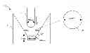
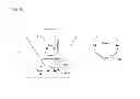
FIG. 1 shows a schematic configuration of a cup test device for evaluating the formability.
DETAILED DESCRIPTION OF THE INVENTION
The copper foil composite of the present invention comprises a copper foil and a resin layer laminated thereon.
<Copper Foil>
The copper foil may contain at least one selected from the group consisting of Sn, Mn, Cr, Zn, Zr, Mg, Ni, Si and Ag at a total of 30 to 500 mass ppm, and the rest being Cu and unavoidable impurities. The copper foil is a rolled copper foil.
Through studies by the present inventors, it is found that when the copper foil contains the above-described element(s), a {100} plane grows and the bending properties are improved as compared with pure copper. If the content of the above-mentioned element(s) is less than 30 mass ppm, the {100} plane does not grow and the bending properties are decreased. If the content exceeds 500 mass ppm, a shear band is formed upon rolling, the {100} plane does not grow, the bending properties are decreased and recrystallized grains may become non-uniform.
A plane orientation of the copper foil is described like “{100}”, and an X-ray diffraction strength is described like“200”.
As described above, a degree of aggregation I200/I0200 (I200: the X-ray diffraction strength of the 200 plane of the copper foil, I0200: the X-ray diffraction strength of the 200 plane of the copper powder) of the {100} plane of the copper foil is specified to be 30 or more. In this way, the orientation of crystal grains becomes uniform, and the deformation is easily transmitted beyond crystal grain boundaries. If the copper foil is thinned, the copper foil constricts locally beyond the crystal grains and the copper foil alone is not elongated. Accordingly, the copper foil alone may be easily elongated when the crystal grains are fine to some degree and the degree of aggregation is small. On the other hand, the copper composite provided by laminating the copper foil with the resin is affected by the deformation of the resin. Even if the crystal grains and the degree of aggregation of the copper foil alone are large, the copper foil is hardly constricted. Rather, when the crystal grains and the degree of aggregation of the copper foil are high, the copper foil will have low strength, easily follow the deformation of the resin, and have high ductility. As a result, the bending properties of the copper foil composite are improved.
The upper limit of the I200/I0200 is not especially limited, but may be 120 or less, 110 or less, or 100 or less, for example.
A tensile strength of the copper foil is specified to be within 100 to 180 MPa. If the tensile strength of the copper foil is less than 100 MPa, the strength is too low to produce the copper foil composite. If the tensile strength of the copper foil exceeds 180 MPa, no {100} plane grows and the crystal grains become small as stacking fault energy of the texture is increased upon rolling.
An average grain size viewed from a plate surface of the copper foil is 10 to 400 μm. If the average grain size viewed from the plate surface of the copper foil is less than 10 μm, no {100} plane grows and the crystal grains become small as stacking fault energy of the texture is increased upon rolling. If the average grain size viewed from the plate surface of the copper foil exceeds 400 μm, it is difficult to produce the copper foil.
In particular, when the average grain size is within 50 to 400 μm, the bending properties and drawing formability are improved. If the average grain size exceeds 50 μm, the strength of the copper foil is decreased and the crystal grains becomes sufficiently larger than the thickness. Often, the respective crystal grains of the copper foil are directly contacted with the resin (the crystal grains not exposed to the surface of the copper foil are decreased), and the respective crystal grains are directly affected by the deformation of the resin. As a result, the bending properties of the copper foil composite may be improved. The drawing formability is necessary when the copper foil composite is press formed into a predetermined shape, for example.
The average grain size is an average value obtained by measuring grain sizes of the copper foil in a rolling direction and a direction transverse to rolling direction according to JIS H0501, the cutting method. As to a sample where a circuit is formed of the copper foil composite, the average grain size is an average value in a direction parallel to the circuit.
Fracture strain of the copper foil is desirably 5% or more. If the fracture strain is less than 5%, elongation of the copper foil composite may be decreased even if (F×T)/(f×t)≧1 of the copper foil composite is satisfied, as described later. If (F×T)/(f×t)≧1 is satisfied, the greater fracture strain of the copper foil is desirable.
When the copper foil is used for an electromagnetic shielding material, the thickness t of the copper foil is desirably 4 to 12 μm. If the thickness t is less than 4 μm, the shielding properties and the fracture strain are decreased and handling may be difficult when the copper foil is produced or laminated with the resin layer. On the other hand, the greater the thickness t is, the more the fracture strain is increased. However, if the thickness t exceeds 12 μm, stiffness may be increased to decrease the formability. If the thickness t exceeds 12 μm, (F×T)/(f×t)≧1 of the copper foil composite as described later is not satisfied and the fracture strain of the copper foil composite may be rather decreased. In particular, if the thickness t exceeds 12 μm, thickness T has to be increased to satisfy (F×T)/(f×t)≧1.
On the other hand, when the copper foil is used for FPC, or a substrate where heat dissipation is necessary, the thickness t of the copper foil is desirably 4 to 40 μm. As to the FPC, or the substrate where heat dissipation is necessary, no flexibility is necessary in the copper foil composite as compared with the case that the copper foil composite is used for the electromagnetic shielding material, a maximum value of the thickness t can be 40 μm. When PI is used as the resin layer, (F×T)/(f×t)≧1 can be satisfied even if the thickness t of the copper foil is thick, because the PI has high strength. The substrate to be heat dissipated is configured and used such that no circuit is formed on the copper foil in the FPC and the copper foil is intimately contacted with a heat dissipation body.
<Resin Layer>
The resin layer is not especially limited, and may be formed by applying a resin material to the copper foil. As the resin layer, a resin film that can be adhered to the copper foil is desirably used. Examples of the resin film include a PET (polyethylene terephthalate) film, a PI (polyimide) film, an LCP (liquid crystal polymer) film and a PP (polypropylene) film. In particular, the PI film is desirably used.
The thickness T of the resin layer is not especially limited, but is generally 7 to 25 μm for the electromagnetic shielding material. If the thickness T is less than 7 μm, a value of (F×T), which is described later, may be decreased, (F×T)/(f×t)≧1 is not satisfied, and the (elongation) fracture strain of the copper foil composite may be decreased. On the other hand, if the thickness T exceeds 25 μm, the (elongation) fracture strain of the copper foil composite may also be decreased.
The resin film may be laminated on the copper foil using an adhesive agent between the resin film and the copper foil, or may be thermally compressed to the copper foil without using an adhesive agent. In order to avoid excess heat, an adhesive agent is desirably used. The thickness of the adhesive layer is desirably 6 μm or less. If the thickness of the adhesive layer exceeds 6 μm, only the copper foil may be easily broken after the lamination of the copper foil composite.
On the other hand, when the copper foil is used for FPC, or a substrate where heat dissipation is necessary, the thickness T of the resin layer is generally about 7 to 70 μm. If the thickness T is less than 7 μm, the value of (F×T)/(f×t)≧1, as described later, is decreased, (F×T)/(f×t)≧1 is not satisfied, and the (elongation) fracture strain of the copper foil composite may be decreased. On the other hand, if the thickness T exceeds 70 μm, the flexibility may be decreased.
The “resin layer” according to the present invention includes an adhesive layer. The FPC may have the resin layers on both surfaces of the copper foil by attaching a coverlay film. In this case, F and T of the resin layer include the strength and the thickness of the coverlay.
An Sn plating layer may be formed at a thickness of about 1 μm on a surface of the copper foil opposite to the surface on which the resin layer is formed, in order to improve corrosion resistance (salinity tolerance) or to decrease contact resistance.
In addition, a surface treatment such as a roughening treatment may be applied to the copper foil in order to improve the adhesion strength between the resin layer and the copper foil. As the surface treatment, those described in Japanese Unexamined Patent Publication No. 2002-217507, Japanese Unexamined Patent Publication No. 2005-15861, Japanese Unexamined Patent Publication No. 2005-4826, and Japanese Examined Patent Publication No. Hei7-32307 and the like can be applied.
By specifying the thickness or the strain of the copper foil and the resin layer in the copper foil composite, the drawing formability can be improved without impairing the formability.
In other words, it is found that when the copper foil composite satisfies (F×T)/(f×t) 1, where t is a thickness of the copper foil, f is a stress of the copper foil under tensile strain of 4%, T is a thickness of the resin layer, and F is a stress of the resin layer under tensile strain of 4%, the ductility is increased and the drawing formability is improved.
The reason is uncertain. However, as each of (F×T) and (f×t) represents the stress per unit width (for example, (N/mm)) and the copper foil and the resin layer are laminated to have the same width, (F×T)/(f×t) represents a ratio of strength added to the copper foil and the resin layer in the copper foil composite. Therefore, when the ratio is 1 or more, more strength is added on the resin layer and the resin layer will be stronger than the copper foil. It can be concluded that, since the copper foil may be easily affected by the resin layer and will be elongated uniformly, the ductility of the whole copper foil composite is increased.
Here, F and f may be the stresses at the same strain amount after plastic deformation is produced. In view of fracture strain of the copper foil and strain at a start of the plastic deformation of the resin layer (for example, the PET film), the stresses are at tensile strain of 4%. F can be measured by a tensile test of the copper foil remained after the resin layer is removed from the copper foil composite using a solvent etc. Similarly, f can be measured by a tensile test of the resin layer remained after the copper foil is removed from the copper foil composite using acid etc. T and t can be measured by observing a section of the copper foil composite using a variety of microscopes (SEM etc.).
If the values of F and f of the copper foil and the resin layer obtained before the copper foil composite is produced are known and if no heat treatment is conducted upon the production of the copper foil composite so that the properties of the copper foil and the resin layer are not greatly changed, the above-described known values of F and f obtained before the copper foil composite is produced may be used.
As described above, when (F×T)/(f×t)≧1 of the copper foil composite is satisfied, the ductility of the copper foil composite becomes high and the fracture strain is also improved. Desirably, when the fracture strain of the copper foil composite is 30% or more, after the copper foil composite is externally wound around a shielding material such as a cable to form a shielding material, cracks are less generated when the copper foil composite is bent accompanied by a cable drag.
The value of the fracture strain of the copper foil composite is provided by employing the strain when the copper foil and the resin layer are broken concurrently by a tensile test, or by employing the strain when only the copper foil is firstly cracked.
EXAMPLES
1. Copper Foil Composite
<Production of Copper Foil Composite>
Each ingot to which respective elements shown in Tables 1 to 3 were added to tough-pitch copper (JIS-H3100 (alloy No.: C1100)) was hot-rolled, or each ingot to which respective elements shown in Tables 4 were added to oxygen-free copper (JIS-H3100 (alloy No.: C1020)) was hot-rolled, surface grinded to remove oxides, cold-rolled, and annealed and acid picking repeatedly to a predetermined thickness. Cold-rolling at a thickness of 0.1 mm or less was conducted by heating copper was at 100 to 110° C., whereby the copper foil having formability was provided. In order to provide the copper foil with a uniform texture in a width direction, tension upon cold-rolling and rolling reduction conditions of the rolled material in a width direction were constant. A plurality of heaters was used to control the temperature so that a uniform temperature distribution during cold-rolling was attained in the width direction, and the temperature of the copper was measured and controlled.
In each of Examples and Comparative Examples 1 to 5, and Comparative Examples 14 to 17, the cold-rolling at a plate thickness of 0.1 mm or less was conducted by heating the copper foil at 100 to 110° C. Also, in each of Examples and Comparative Examples 1 to 5, and Comparative Examples 14 to 17, it was controlled that a rolling reduction ratio per one pass did not exceed 25% when the cold-rolling at a plate thickness of 0.1 mm or less was conducted.
On the other hand, in each of Comparative Examples 6 to 8, 10 to 13 and 18, upon the cold-rolling at a plate thickness of 0.1 mm or less the copper foil was not heated at 100 to 110° C. during rolling. Also, in each of Comparative Examples 6 to 8, 10 to 13 and 18, some of the rolling reduction ratio per one pass exceeded 25% when the cold-rolling at a plate thickness of 0.1 mm or less was conducted.
In Comparative Examples 19, the cold-rolling at a plate thickness of 0.1 mm or less was conducted by heating the copper foil at 100 to 110° C. during rolling, and some of the rolling reduction ratio per one pass exceeded 25% when the cold-rolling at a plate thickness of 0.1 mm or less was conducted.
In Comparative Example 20, upon the cold-rolling at a plate thickness of 0.1 mm or less the copper foil was not heated at 100 to 110° C. during rolling, and it was controlled that the rolling reduction ratio per one pass did not exceed 25% when the cold-rolling at a plate thickness of 0.1 mm or less was conducted.
In Comparative Example 9, an electrolyte copper foil was used.
A typical surface treatment used in CCL was conducted on the surface of the resultant copper foil. The surface treatment described in Japanese Examined Patent Publication No. Hei7-3237 was used. After the surface treatment, a PI layer, i.e., the resin layer, was laminated on the copper foil to produce a CCL (copper foil composite). The resin layer was laminated on the copper foil under the known conditions. When the PI layer was laminated on the copper foil, a thermoplastic PI base adhesive layer was interposed between the PI layer and the copper foil. The adhesive layer and the PI film constituted the resin layer.
<Tensile Test>
A plurality of strip test specimens each having a width of 12.7 mm were produced from the copper foil composites. Some strip test specimens were immersed in a solvent (TPE3000 manufactured by Toray Engineering Co., Ltd.,) to dissolve the adhesion layer and the PI film and to provide the test specimens each having only the copper foil. In some test specimens, the copper foils were dissolved with ferric chloride and the like to provide the test specimens of the only total layer having the PI.
The tensile test was conducted under the conditions that a gauge length was 100 mm and the tension speed was 10 mm/min. An average value of N10 was employed for strength (stress) and elongation.
<Aggregation Texture of Copper Foil I200/I0200>
Each copper foil composite was immersed in a solvent (TPE3000 manufactured by Toray Engineering Co., Ltd.) to dissolve the adhesive layer and the PI film, thereby providing a test specimen composed of only the copper foil. Then, a value of integral (I) of the {100} plane strength on the rolled surface of the copper foil measured by the X-ray diffraction was determined. This values was divided by a value of integral (I0) of the {100} plane strength of copper fine powder (325 mesh, used after heating at 300° C. under hydrogen stream for one hour) to calculate the I200/I0200.
<Evaluation of Copper Foil Composite>
<W-Bending (Formability)>
According to Japan Copper and Brass Association, technical standard, JCBA T307, the copper foil composite was W-bended at bending radius R=0 mm. The W-bending is for evaluating formability of the general copper foil composite.
<180° Intimate Bending>
According to JIS Z 2248, the copper foil composite was tested for 180° intimate bending. The 180° intimate bending is stricter than the W-bending, and is for evaluating the bending properties of the copper foil composite. Next, the bent part at 180° was returned to 0°, and again bent at 180°. After 180° intimate bending were performed five times, the surfaces of the bent copper foils were observed.
<Drawing Formability>
The formability was evaluated using a cup test device 10 shown in FIG. 1. The cup test machine 10 comprised a die 4 and a punch 2. The die 4 had a frustum slope. The frustum was tapered from up to down. The frustum slope was tilted at an angle of 60° from a horizontal surface. The bottom of the frustum was communicated with a circular hole having a diameter of 15 mm and a depth of 7 mm. The punch 2 was a cylinder and had a tip in a semispherical shape with a diameter of 14 mm. The semispherical tip of the punch 2 could be inserted into the circular hole of the frustum.
A connection part of the tapered tip of the frustum and the circular hole at the bottom of the frustum was rounded by a radius (r)=3 mm.
The copper foil composite was punched out to provide the test specimen 20 in a circular plate shape with a diameter of 30 mm, and was disposed on the slope of the frustum of the die 4. The punch 2 was pushed down on the top of the test specimen 20 to insert it into the circular hole of the die 4. Thus, the test specimen 20 was formed in a conical cup shape.
In the case the resin layer was disposed on one surface of the copper foil composite, the copper foil composite was disposed on the die 4 such that the resin layer was faced upward. In the case the resin layers were disposed on both surfaces of the copper foil composite, the copper foil composite was disposed on the die 4 such that the resin layer bonded to the M surface was faced upward. In the case the both surfaces of the copper foil composite was Cu, either surface might be faced upward.
After molding, the crack of the copper foil in the test specimen 20 was visually identified. The formability was evaluated the following scales:
These copper foil composites were evaluated by the following scales:
Excellent: the copper foil was not cracked and had no necking.
Good: the copper foil had small wrinkles (necking) but had no large ones.
Not Bad: the copper foil had large necking, but was not cracked.
Bad: the copper foil was cracked.
As to the W-bending and the 180° intimate bending, Excellent and Good results are OK. As to the drawing formability, Excellent, Good and Not Bad results are OK.
The results are shown in Tables 1 to 3. In Tables, “TS” denotes tensile strength, “GS” denotes a grain size, and I/I0 denotes the I200/I0200. A method of measuring the GS is as described above. Specifically, the copper foil composite is immersed into the solvent (TPE3000 manufactured by Toray Engineering Co., Ltd.) to dissolve the adhesion layer and the PI film and to provide the test specimens each having only the copper foil. These copper foils were measured for GS.
| TABLE 1 | ||
| Copper foil | Resin layer |
| Added | ||||||||||||
| Element | TS | f | GS | Elonga- | t | TS | F | T | Elonga- | |||
| (wtppm) | (MPa) | (MPa) | (μm) | 1/10 | tion (%) | (μm) | type | (MPa) | (MPa) | (μm) | tion (%) | |
| Example 1 | Ag: 200 | 115 | 110 | 95 | 55 | 4.5 | 9 | PI | 365 | 167 | 14 | 54 |
| Example 2 | Ag: 200 | 120 | 114 | 78 | 35 | 4.7 | 9 | PI | 365 | 167 | 14 | 54 |
| Example 3 | Ag: 50 | 101 | 96 | 135 | 70 | 4.5 | 12 | PI | 365 | 167 | 14 | 54 |
| Example 4 | Ag: 100 | 105 | 95 | 132 | 75 | 4.8 | 12 | PI | 365 | 167 | 14 | 54 |
| Example 5 | Ag: 200 | 125 | 110 | 110 | 80 | 5.8 | 12 | PI | 365 | 167 | 14 | 54 |
| Example 6 | Ag: 500 | 147 | 113 | 70 | 35 | 7.3 | 12 | PI | 365 | 167 | 14 | 54 |
| Example 7 | Sn: 50 | 110 | 105 | 130 | 63 | 4.5 | 12 | PI | 365 | 167 | 14 | 54 |
| Example 8 | Sn: 100 | 118 | 110 | 105 | 65 | 4.9 | 12 | PI | 365 | 167 | 14 | 54 |
| Example 9 | Sn: 170 | 148 | 118 | 80 | 58 | 6.5 | 12 | PI | 365 | 167 | 14 | 54 |
| Example 10 | Ag: 50, | 120 | 110 | 128 | 69 | 5.1 | 12 | PI | 365 | 167 | 14 | 54 |
| Sn: 50 | ||||||||||||
| Example 12 | Zn: 100 | 172 | 125 | 20 | 40 | 8.3 | 12 | PI | 365 | 167 | 14 | 54 |
| Example 13 | Ag: 50 | 122 | 108 | 55 | 55 | 5.1 | 12 | PI | 365 | 167 | 14 | 54 |
| Zn: 50 | ||||||||||||
| Example 14 | Ag: 50 | 113 | 96 | 138 | 75 | 5.6 | 18 | PI | 365 | 167 | 14 | 54 |
| Example 15 | Ag: 100 | 113 | 100 | 142 | 83 | 5.1 | 18 | PI | 365 | 167 | 14 | 54 |
| Example 16 | Ag: 200 | 128 | 105 | 143 | 92 | 6.3 | 18 | PI | 365 | 167 | 14 | 54 |
| Example 17 | Ag: 200 | 110 | 90 | 370 | 96 | 5.5 | 18 | PI | 365 | 167 | 14 | 54 |
| Example 18 | Ag: 500 | 135 | 110 | 75 | 35 | 6.6 | 18 | PI | 365 | 167 | 14 | 54 |
| Example 19 | Sn: 50 | 125 | 105 | 135 | 72 | 5.8 | 18 | PI | 365 | 167 | 14 | 54 |
| Example 20 | Sn: 100 | 128 | 113 | 110 | 65 | 5.6 | 18 | PI | 365 | 167 | 14 | 54 |
| Example 22 | Ag: 50, | 125 | 106 | 130 | 75 | 6.1 | 18 | PI | 365 | 167 | 14 | 54 |
| Sn: 50 | ||||||||||||
| Example 23 | Zn: 50 | 158 | 120 | 46 | 50 | 7.5 | 18 | PI | 365 | 167 | 14 | 54 |
| Example 24 | Zn: 100 | 180 | 120 | 24 | 46 | 10.1 | 18 | PI | 365 | 167 | 14 | 54 |
| Example 26 | Ag: 50 | 101 | 96 | 135 | 70 | 4.5 | 12 | PI | 360 | 170 | 26 | 57 |
| Example 27 | Ag: 100 | 105 | 95 | 132 | 75 | 4.8 | 12 | PI | 360 | 170 | 26 | 57 |
| Example 28 | Ag: 200 | 125 | 110 | 110 | 80 | 5.8 | 12 | PI | 360 | 170 | 26 | 57 |
| Example 29 | Ag: 500 | 147 | 113 | 70 | 35 | 7.3 | 12 | PI | 360 | 170 | 26 | 57 |
| Example 30 | Sn: 50 | 110 | 105 | 130 | 63 | 4.5 | 12 | PI | 360 | 170 | 26 | 57 |
| Copper foil composite |
| 180 degree | ||||||
| Elonga- | W- | intimate | Drawing | (F × T)/ | ||
| tion (%) | bending | bending | formability | (f × t) | ||
| Example 1 | 52 | Excellent | Excellent | Excellent | 2.4 | |
| Example 2 | 48 | Excellent | Excellent | Excellent | 2.3 | |
| Example 3 | 48 | Excellent | Excellent | Excellent | 2.0 | |
| Example 4 | 47 | Excellent | Excellent | Excellent | 2.1 | |
| Example 5 | 53 | Excellent | Excellent | Excellent | 1.8 | |
| Example 6 | 45 | Excellent | Excellent | Excellent | 1.7 | |
| Example 7 | 46 | Excellent | Excellent | Excellent | 1.9 | |
| Example 8 | 45 | Excellent | Excellent | Excellent | 1.8 | |
| Example 9 | 43 | Excellent | Excellent | Excellent | 1.7 | |
| Example 10 | 41 | Excellent | Excellent | Good | 1.8 | |
| Example 12 | 37 | Excellent | Good | Good | 1.6 | |
| Example 13 | 45 | Excellent | Excellent | Excellent | 1.8 | |
| Example 14 | 47 | Excellent | Excellent | Excellent | 1.4 | |
| Example 15 | 45 | Excellent | Excellent | Excellent | 1.3 | |
| Example 16 | 45 | Excellent | Excellent | Excellent | 1.2 | |
| Example 17 | 50 | Excellent | Excellent | Excellent | 1.4 | |
| Example 18 | 45 | Excellent | Excellent | Excellent | 1.2 | |
| Example 19 | 46 | Excellent | Excellent | Excellent | 1.2 | |
| Example 20 | 46 | Excellent | Excellent | Excellent | 1.1 | |
| Example 22 | 47 | Excellent | Good | Good | 1.2 | |
| Example 23 | 38 | Excellent | Good | Good | 1.1 | |
| Example 24 | 38 | Excellent | Good | Good | 1.1 | |
| Example 26 | 53 | Excellent | Excellent | Excellent | 3.8 | |
| Example 27 | 53 | Excellent | Excellent | Excellent | 3.9 | |
| Example 28 | 46 | Excellent | Excellent | Excellent | 3.3 | |
| Example 29 | 45 | Excellent | Excellent | Excellent | 3.3 | |
| Example 30 | 45 | Excellent | Excellent | Excellent | 3.5 | |
| TABLE 2 | ||
| Copper foil | Resin layer |
| Added | ||||||||||||
| Element | TS | f | GS | Elonga- | t | TS | F | T | Elonga- | |||
| (wtppm) | (MPa) | (MPa) | (μm) | 1/10 | tion (%) | (μm) | type | (MPa) | (MPa) | (μm) | tion (%) | |
| Example 31 | Sn: 100 | 118 | 110 | 105 | 65 | 4.9 | 12 | PI | 360 | 170 | 26 | 57 |
| Example 32 | Sn: 200 | 148 | 118 | 80 | 58 | 6.5 | 12 | PI | 360 | 170 | 26 | 57 |
| Example 33 | Ag: 50, | 120 | 110 | 128 | 69 | 5.1 | 12 | PI | 360 | 170 | 26 | 57 |
| Sn: 50 | ||||||||||||
| Example 34 | Zn: 50 | 155 | 120 | 45 | 45 | 7.2 | 12 | PI | 360 | 170 | 26 | 57 |
| Example 35 | Zn: 100 | 172 | 125 | 20 | 40 | 8.3 | 12 | PI | 360 | 170 | 26 | 57 |
| Example 36 | Ag: 50 | 122 | 108 | 55 | 55 | 5.1 | 12 | PI | 360 | 170 | 26 | 57 |
| Zn: 50 | ||||||||||||
| Example 38 | Ag: 100 | 105 | 95 | 132 | 75 | 4.8 | 12 | PI | 353 | 165 | 39 | 65 |
| Example 39 | Ag: 200 | 125 | 110 | 110 | 80 | 5.8 | 12 | PI | 353 | 165 | 39 | 65 |
| Example 40 | Ag: 500 | 147 | 113 | 70 | 35 | 7.3 | 12 | PI | 353 | 165 | 39 | 65 |
| Example 41 | Sn : 50 | 110 | 105 | 130 | 63 | 4.5 | 12 | PI | 353 | 165 | 39 | 65 |
| Example 42 | Sn: 100 | 118 | 110 | 105 | 65 | 4.9 | 12 | PI | 353 | 165 | 39 | 65 |
| Example 43 | Sn: 200 | 148 | 118 | 80 | 58 | 6.5 | 12 | PI | 353 | 165 | 39 | 65 |
| Example 44 | Ag: 50, | 120 | 110 | 128 | 69 | 5.1 | 12 | PI | 353 | 165 | 39 | 65 |
| Sn: 50 | ||||||||||||
| Example 45 | Zn: 50 | 155 | 120 | 45 | 45 | 7.2 | 12 | PI | 353 | 165 | 39 | 65 |
| Example 46 | Zn: 100 | 172 | 125 | 20 | 40 | 8.3 | 12 | PI | 353 | 165 | 39 | 65 |
| Example 47 | Ag: 50 | 122 | 108 | 55 | 55 | 5.1 | 12 | PI | 353 | 165 | 39 | 65 |
| Zn: 50 | ||||||||||||
| Example 48 | Ag: 50 | 135 | 112 | 143 | 70 | 6.5 | 32 | PI | 353 | 165 | 39 | 65 |
| Example 49 | Ag: 100 | 138 | 98 | 140 | 72 | 8.2 | 32 | PI | 353 | 165 | 39 | 65 |
| Example 50 | Ag: 200 | 148 | 110 | 132 | 78 | 8.1 | 32 | PI | 353 | 165 | 39 | 65 |
| Example 51 | Ag: 300 | 150 | 115 | 74 | 40 | 8.7 | 32 | PI | 353 | 165 | 39 | 65 |
| Example 52 | Sn: 50 | 140 | 112 | 125 | 60 | 6.9 | 32 | PI | 353 | 165 | 39 | 65 |
| Example 53 | Sn: 100 | 150 | 125 | 110 | 54 | 6.5 | 32 | PI | 353 | 165 | 39 | 65 |
| Example 54 | Ag: 200 | 148 | 110 | 132 | 78 | 7.9 | 32 | PI | 355 | 167 | 51 | 64 |
| Example 55 | Ag: 200 | 148 | 110 | 132 | 78 | 7.9 | 32 | PI | 350 | 167 | 15 | 55 |
| Example 56 | Zn: 100 | 172 | 125 | 20 | 40 | 8.3 | 32 | PI | 350 | 160 | 15 | 55 |
| Example 57 | Ag: 30 | 132 | 113 | 58 | 30 | 9.5 | 18 | PI | 360 | 170 | 26 | 57 |
| Copper foil composite |
| 180 | ||||||
| degree | ||||||
| Elonga- | W- | intimate | Drawing | (F × T)/ | ||
| tion (%) | bending | bending | formability | (f × t) | ||
| Example 31 | 45 | Excellent | Excellent | Excellent | 3.3 | |
| Example 32 | 43 | Excellent | Excellent | Excellent | 3.1 | |
| Example 33 | 44 | Excellent | Excellent | Excellent | 3.3 | |
| Example 34 | 40 | Excellent | Good | Good | 3.1 | |
| Example 35 | 38 | Excellent | Good | Good | 2.9 | |
| Example 36 | 43 | Excellent | Excellent | Excellent | 3.4 | |
| Example 38 | 59 | Excellent | Excellent | Excellent | 5.6 | |
| Example 39 | 51 | Excellent | Excellent | Excellent | 4.9 | |
| Example 40 | 45 | Excellent | Excellent | Excellent | 4.7 | |
| Example 41 | 50 | Excellent | Excellent | Excellent | 5.1 | |
| Example 42 | 49 | Excellent | Excellent | Excellent | 4.9 | |
| Example 43 | 45 | Excellent | Excellent | Excellent | 4.5 | |
| Example 44 | 48 | Excellent | Excellent | Excellent | 4.9 | |
| Example 45 | 41 | Excellent | Good | Good | 4.5 | |
| Example 46 | 40 | Excellent | Good | Good | 4.3 | |
| Example 47 | 50 | Excellent | Excellent | Excellent | 5.0 | |
| Example 48 | 48 | Excellent | Excellent | Excellent | 1.8 | |
| Example 49 | 45 | Excellent | Excellent | Excellent | 2.1 | |
| Example 50 | 43 | Excellent | Excellent | Excellent | 1.8 | |
| Example 51 | 44 | Excellent | Excellent | Excellent | 1.7 | |
| Example 52 | 45 | Excellent | Excellent | Excellent | 1.8 | |
| Example 53 | 48 | Excellent | Excellent | Excellent | 1.6 | |
| Example 54 | 51 | Excellent | Excellent | Excellent | 2.4 | |
| Example 55 | 35 | Excellent | Excellent | Good | 0.7 | |
| Example 56 | 32 | Excellent | Good | Not Bad | 0.6 | |
| Example 57 | 45 | Excellent | Excellent | Excellent | 2.2 | |
| TABLE 3 | ||
| Copper foil | Resin layer |
| Added | ||||||||||||
| Element | TS | f | GS | Elonga- | t | TS | F | T | Elonga- | |||
| (wtppm) | (MPa) | (MPa) | (μm) | 1/10 | tion (%) | (μm) | type | (MPa) | (MPa) | (μm) | tion (%) | |
| Comp. 1 | none | 201 | 149 | 18 | 20 | 7.3 | 7 | PI | 365 | 167 | 13 | 54 |
| Example | (tough-pitch) | |||||||||||
| Comp. | none | 210 | 143 | 20 | 20 | 9.3 | 12 | PI | 365 | 167 | 13 | 54 |
| Example 2 | (tough-pitch) | |||||||||||
| Comp. | none | 200 | 120 | 17 | 25 | 12.2 | 18 | PI | 365 | 167 | 13 | 54 |
| Example 3 | (tough-pitch) | |||||||||||
| Comp. | none | 190 | 130 | 20 | 20 | 9.3 | 12 | PI | 360 | 170 | 25 | 57 |
| Example 4 | (tough-pitch) | |||||||||||
| Comp. | none | 190 | 130 | 20 | 20 | 9.3 | 12 | PI | 353 | 165 | 38 | 65 |
| Example 5 | (tough-pitch) | |||||||||||
| Comp. | Ag: 50 | 140 | 125 | 25 | 23 | 4.8 | 12 | PI | 365 | 167 | 13 | 54 |
| Example 6 | ||||||||||||
| Comp. | Ag: 100 | 147 | 130 | 29 | 26 | 5.1 | 12 | PI | 365 | 167 | 13 | 54 |
| Example 7 | ||||||||||||
| Comp. | Sn: 100 | 138 | 120 | 35 | 25 | 4.4 | 12 | PI | 365 | 167 | 13 | 54 |
| Example 8 | ||||||||||||
| Comp. | electrolyte | 340 | 320 | 7 | 0.7 | 16 | 12 | PI | 365 | 167 | 13 | 54 |
| Example 9 | copper foil | |||||||||||
| Comp. | Ag 2000 | 245 | 220 | 8 | 13 | 15 | 12 | PI | 365 | 167 | 13 | 54 |
| Example 10 | ||||||||||||
| Comp. | Sn 1500 | 230 | 215 | 8 | 4 | 23 | 12 | PI | 365 | 167 | 13 | 54 |
| Example 11 | ||||||||||||
| Comp. | Sn 20 | 131 | 128 | 120 | 25.1 | 4.8 | 9 | PI | 365 | 167 | 13 | 54 |
| Example 12 | ||||||||||||
| Comp. | Sn 60 | 149 | 138 | 35 | 20.1 | 5.5 | 18 | PI | 365 | 167 | 13 | 54 |
| Example 13 | ||||||||||||
| Comp. | none | 185 | 161 | 18 | 64.3 | 15.6 | 35 | PI | 365 | 167 | 13 | 54 |
| Example 14 | (tough-pitch) | |||||||||||
| Comp. | none | 184 | 157 | 17 | 64.1 | 15.3 | 35 | PI | 365 | 167 | 13 | 54 |
| Example 15 | (oxygen- | |||||||||||
| free copper) | ||||||||||||
| Comp. | none | 182 | 155 | 45 | 35.3 | 9.3 | 12 | PI | 365 | 167 | 13 | 54 |
| Example 16 | (oxygen- | |||||||||||
| free copper) | ||||||||||||
| Comp. | none | 181 | 162 | 70 | 94 | 16.1 | 16 | PI | 365 | 167 | 13 | 54 |
| Example 17 | (oxygen- | |||||||||||
| free copper) | ||||||||||||
| Comp. | Ag 1200 | 192 | 165 | 9 | 30.1 | 7.3 | 7 | PI | 365 | 167 | 13 | 54 |
| Example 18 | ||||||||||||
| Comp. | Ag: 100 | 152 | 132 | 29 | 27.5 | 5.1 | 12 | PI | 365 | 167 | 13 | 54 |
| Example 19 | ||||||||||||
| Comp. | Ag: 100 | 148 | 130 | 29 | 27.7 | 5.1 | 12 | PI | 365 | 167 | 13 | 54 |
| Example 20 | ||||||||||||
| Copper foil composite |
| 180 | Draw- | |||||
| degree | ing | |||||
| Elonga- | W- | intimate | form- | (F × T)/ | ||
| tion (%) | bending | bending | ability | (f × t) | ||
| Comp. | 24 | Excellent | Bad | Bad | 2.1 | |
| Example 1 | ||||||
| Comp. | 23 | Excellent | Bad | Bad | 1.3 | |
| Example 2 | ||||||
| Comp. | 22 | Excellent | Bad | Bad | 1.0 | |
| Example 3 | ||||||
| Comp. | 23 | Excellent | Bad | Bad | 2.7 | |
| Example 4 | ||||||
| Comp. | 23 | Excellent | Bad | Bad | 4.0 | |
| Example 5 | ||||||
| Comp. | 27 | Excellent | Not | Bad | 1.4 | |
| Example 6 | Bad | |||||
| Comp. | 26 | Excellent | Not | Bad | 1.4 | |
| Example 7 | Bad | |||||
| Comp. | 27 | Excellent | Not | Bad | 1.5 | |
| Example 8 | Bad | |||||
| Comp. | 18 | Bad | Bad | Bad | 0.6 | |
| Example 9 | ||||||
| Comp. | 17 | Bad | Bad | Bad | 0.8 | |
| Example 10 | ||||||
| Comp. | 18 | Bad | Bad | Bad | 0.8 | |
| Example 11 | ||||||
| Comp. | 21 | Excellent | Not | Bad | 1.9 | |
| Example 12 | Bad | |||||
| Comp. | 18 | Excellent | Bad | Bad | 0.9 | |
| Example 13 | ||||||
| Comp. | 17 | Excellent | Not | Bad | 0.4 | |
| Example 14 | Bad | |||||
| Comp. | 16 | Excellent | Not | Bad | 0.4 | |
| Example 15 | Bad | |||||
| Comp. | 20 | Excellent | Not | Bad | 1.2 | |
| Example 16 | Bad | |||||
| Comp. | 18 | Excellent | Not | Bad | 0.8 | |
| Example 17 | Bad | |||||
| Comp. | 23 | Excellent | Bad | Bad | 1.9 | |
| Example 18 | ||||||
| Comp. | 24 | Excellent | Not | Bad | 1.4 | |
| Example 19 | Bad | |||||
| Comp. | 24 | Excellent | Not | Bad | 1.4 | |
| Example 20 | Bad | |||||
| TABLE 4 | ||
| Copper foil | Resin layer |
| Added Element | TS | f | GS | Elonga- | t | TS | F | T | Elonga- | |||
| (wtppm) | (MPa) | (MPa) | (μm) | 1/10 | tion (%) | (μm) | type | (MPa) | (MPa) | (μm) | tion (%) | |
| Example 60 | Ag: 30 | 135 | 121 | 33 | 30 | 4.5 | 9 | PI | 365 | 167 | 14 | 54 |
| Example 61 | Ag: 200 | 133 | 123 | 53 | 32 | 4.7 | 9 | PI | 365 | 167 | 14 | 54 |
| Example 62 | Ag: 50 | 140 | 125 | 52 | 44 | 6.2 | 12 | PI | 365 | 167 | 14 | 54 |
| Example 63 | Ag: 100 | 145 | 120 | 50 | 42 | 6.7 | 12 | PI | 365 | 167 | 14 | 54 |
| Example 64 | Ag: 180 | 152 | 125 | 121 | 67 | 12.5 | 18 | PI | 365 | 167 | 14 | 54 |
| Example 65 | Ag: 130 | 153 | 121 | 125 | 65 | 13.7 | 18 | PI | 365 | 167 | 14 | 54 |
| Example 66 | Sn: 50 | 150 | 125 | 83 | 50 | 13.3 | 18 | PI | 365 | 167 | 14 | 54 |
| Example 67 | Sn: 100 | 140 | 122 | 58 | 35 | 8.2 | 12 | PI | 365 | 167 | 14 | 54 |
| Example 68 | Sn: 170 | 141 | 120 | 32 | 41 | 7.5 | 12 | PI | 365 | 167 | 14 | 54 |
| Example 69 | Ag: 50, Sn: 30 | 139 | 124 | 110 | 44 | 7.9 | 12 | PI | 365 | 167 | 14 | 54 |
| Example 70 | Zn: 100 | 138 | 122 | 38 | 49 | 6.8 | 12 | PI | 365 | 167 | 14 | 54 |
| Example 71 | Ag: 50, Zn: 50 | 133 | 120 | 60 | 42 | 7.5 | 12 | PI | 365 | 167 | 14 | 54 |
| Copper foil composite |
| 180 degree | ||||||
| Elonga- | W- | intimate | Drawing | (F × T)/ | ||
| tion (%) | bending | bending | formability | (f × t) | ||
| Example 60 | 38 | Excellent | Good | Good | 2.1 | |
| Example 61 | 53 | Excellent | Excellent | Excellent | 2.1 | |
| Example 62 | 50 | Excellent | Excellent | Excellent | 1.6 | |
| Example 63 | 52 | Excellent | Excellent | Excellent | 1.6 | |
| Example 64 | 48 | Excellent | Excellent | Excellent | 1.0 | |
| Example 65 | 53 | Excellent | Excellent | Excellent | 1.1 | |
| Example 66 | 47 | Excellent | Excellent | Excellent | 1.0 | |
| Example 67 | 51 | Excellent | Excellent | Excellent | 1.6 | |
| Example 68 | 39 | Excellent | Good | Good | 1.6 | |
| Example 69 | 47 | Excellent | Excellent | Excellent | 1.6 | |
| Example 70 | 37 | Excellent | Good | Good | 1.6 | |
| Example 71 | 45 | Excellent | Excellent | Excellent | 1.6 | |
As apparent from Tables 1 to 4, in each Examples, the tensile strength (TS) of the copper foil was 100 to 180 MPa, the I200/I0200 was 30 or more, the average grain size viewed from the plate surface of the copper foil was 10 to 400 μm, the formability of the copper foil composite was excellent and the bending properties and the drawing formability were also excellent.
Although the drawing formability of each of Examples 12, 23, 24, 34, 35, 45, 46, 60, 68 and 70 having the average grain size viewed from the plate surface of the copper foil being less than 50 μm was somewhat inferior as compared with other Examples, there is no practical problem. In view of this, it is desirable that the average grain size viewed from the plate surface of the copper foil is 50 to 400 μm.
In Example 55, the copper foil being identical with that in Example 54 was used but the resin layer was controlled to have (F×T)/(f×t)<1. Similarly, in Example 56, the copper foil being identical with that in Example 46 was used but the resin layer was controlled to have (F×T)/(f×t)<1. By comparing Example 55 with Example 54 and Example 56 with Example 46, it is found that the drawing formability becomes better when (F×T)/(f×t)≧1 is satisfied.
On the other hand, in each of Comparative Examples 1 to 5, it was controlled so that the temperature of the copper upon cold-rolling was at 100 to 110° C. and the rolling reduction ratio per one pass did not exceed 25% when the cold-rolling at the plate thickness of 0.1 mm or less, the average grain size viewed from the plate surface of the copper foil was 10 to 400 μm, resulting in excellent formability of the copper foil composite. However, as the tough-pitch copper (JIS-H3250 standard) containing no above-mentioned elements was used, the I200/I0200 was less than 30 and the bending properties and the drawing formability were poor. Similarly, in Comparative Example 12 where the content of the above-mentioned elements was less than 30 wt ppm, the bending properties and the drawing formability of the copper foil composite were poor.
In each of Comparative Examples 6 to 8, the copper foil was not heated at 100 to 110° C. upon the cold-rolling at the plate thickness of 0.1 mm or less, and a part of the rolling reduction ratio per one pass exceeded 25% when the cold-rolling, the I200/I0200 was less than 30 and the bending properties and the drawing formability were poor. In Comparative Example 9 using an electrolyte copper foil, the average grain size of the copper foil was less than 10 μm, the I200/I0200 was less than 30 and the bending properties and the drawing formability of the copper foil composite were poor.
In each of Comparative Examples 10, 11 and 18, the copper foil was not heated at 100 to 110° C. upon the cold-rolling at the plate thickness of 0.1 mm or less, a part of the rolling reduction ratio per one pass exceeded 25% when the cold-rolling, and the content of the above-mentioned elements exceeded 500 wt ppm, the recrystallized grains became non-uniform and the average grain size of the copper foil was less than 10 μm. Thus, the formability of the copper foil composite was poor. Furthermore, the shear band was formed upon the rolling, the {100} plane did not grow and the I200/I0200 was less than 30, thus the bending properties and the drawing properties of the copper foil composite were poor.
In Comparative Example 13, as the copper foil was not heated at 100 to 110° C. upon the cold-rolling at the plate thickness of 0.1 mm or less and a part of the rolling reduction ratio per one pass exceeded 25% upon the cold-rolling, the I200/I0200 was less than 30 and the bending properties and the drawing formability of the copper foil composite were poor.
In each of Comparative Examples 14 to 17 where at least one selected from the group consisting of Sn, Mn, Cr, Zn, Zr, Mg, Ni, Si and Ag was not added, the TS exceeded 180 MPa and the bending properties and the drawing formability of the copper foil composite were poor.
In Comparative Example 19, as the copper foil was heated at 100 to 110° C. upon the cold-rolling at the plate thickness of 0.1 mm or less but a part of the rolling reduction ratio per one pass exceeded 25% when the cold-rolling, the I200/I0200 was less than 30 and the bending properties and the drawing formability of the copper foil composite were poor.
In Comparative Examples 20, as it was controlled that the rolling reduction ratio per one pass did not exceed 25% when the cold-rolling, but the copper foil was not heated at 100 to 110° C. upon the cold-rolling at the plate thickness of 0.1 mm or less, the I200/I0200 was less than 30 and the bending properties and the drawing formability of the copper foil composite were poor.
Claims
What is claimed is:1. A copper foil composite comprising a copper foil and a resin layer laminated, the copper foil containing at least one selected from the group consisting of Sn, Mn, Cr, Zn, Zr, Mg, Ni, Si and Ag at a total of 30 to 500 mass ppm, a tensile strength of the copper foil having of 100 to 180 MPa, a degree of aggregation I200/I0200 of a (100) plane of the copper foil being 30 or more, and an average grain size viewed from a plate surface of the copper foil being 10 to 400 μm.
2. The copper foil composite according to claim 1, wherein the average grain size viewed from the plate surface of the copper foil is 50 to 400 μm.
3. The copper foil composite according to claim 1, wherein fracture strain of the copper foil being 5% or more, and (F×T)/(f×t)≧1 is satisfied, where t is a thickness of the copper foil, f is a stress of the copper foil under tensile strain of 4%, T is a thickness of the resin layer, and F is a stress of the resin layer under tensile strain of 4%.
4. A copper foil, used for the copper foil composite according to claim 1.
5. A formed product, provided by working the copper foil composite according to claim 1.
6. A method of producing a formed product, comprising working the copper foil composite according to claim 1.
7. The copper foil composite according to claim 2, wherein fracture strain of the copper foil being 5% or more, and (F×T)/(f×t)≧1 is satisfied, where t is a thickness of the copper foil, f is a stress of the copper foil under tensile strain of 4%, T is a thickness of the resin layer, and F is a stress of the resin layer under tensile strain of 4%.
Images & Drawings included:
Sources:
- United States Patent and Trademark Office - verify current appl. status at the USPTO↗
Recent applications in this class:
- » 20250294715 2025-09-18
METHOD FOR PRODUCING TRANSPARENT CONDUCTIVE COATINGS FOR EMI PROTECTION USING HIPIMS - » 20250063707 2025-02-20
ASSEMBLY FOR ELECTRIC FIELD GENERATION OR ELECTRIC FIELD CONVERSION VIA CAPACITIVE COUPLING - » 20250008715 2025-01-02
METHOD FOR PROTECTING IR TRANSMITTING WINDOWS AND DOMES FROM EMI - » 20240389290 2024-11-21
ELECTROMAGNETIC WAVE SHIELD FILM - » 20240324159 2024-09-26
HIGH FREQUENCY DIFFUSION SHEET - » 20240292584 2024-08-29
DISPLAY DEVICE - » 20240276691 2024-08-15
MODULE - » 20240188267 2024-06-06
Electromagnetic wave shield film - » 20240188266 2024-06-06
ELECTRONIC ASSEMBLY WITH ELECTROMAGNETIC SHIELDING - » 20240164077 2024-05-16
Electromagnetic Wave Shield Film
Recent applications for this Assignee:
- » 20250083227 2025-03-13
COPPER ALLOY POWDER FOR LAMINATION SHAPING, LAMINATION SHAPED PRODUCT PRODUCTION METHOD, AND LAMINATION SHAPED PRODUCT - » 20240186604 2024-06-06
TREATMENT METHOD FOR BATTERY WASTE - » 20240079582 2024-03-07
POSITIVE ELECTRODE ACTIVE MATERIAL FOR LITHIUM ION BATTERIES, POSITIVE ELECTRODE FOR LITHIUM ION BATTERIES, LITHIUM ION BATTERY, POSITIVE ELECTRODE ACTIVE MATERIAL FOR ALL-SOLID LITHIUM ION BATTERIES, POSITIVE ELECTRODE FOR ALL-SOLID LITHIUM ION BATTERIES, ALL-SOLID LITHIUM ION BATTERY, METHOD FOR PRODUCING POSITIVE ELECTRODE ACTIVE MATERIAL FOR LITHIUM ION BATTERIES, AND METHOD FOR PRODUCING POSITIVE ELECTRODE ACTIVE MATERIAL FOR ALL-SOLID LITHIUM ION BATTERIES - » 20240057305 2024-02-15
Electromagnetic shielding material - » 20230392289 2023-12-07
INDIUM PHOSPHIDE SUBSTRATE, METHOD FOR MANUFACTURING INDIUM PHOSPHIDE SUBSTRATE, AND SEMICONDUCTOR EPITAXIAL WAFER - » 20230378274 2023-11-23
INDIUM PHOSPHIDE SUBSTRATE, METHOD FOR MANUFACTURING INDIUM PHOSPHIDE SUBSTRATE, AND SEMICONDUCTOR EPITAXIAL WAFER - » 20230374700 2023-11-23
Indium phosphide substrate, semiconductor epitaxial wafer, method for producing indium phosphide single-crystal ingot and method for producing indium phosphide substrate - » 20230312369 2023-10-05
METHOD FOR PRODUCING MIXED METAL SALT - » 20230304130 2023-09-28
METHOD FOR RECOVERING LITHIUM FROM LITHIUM ION BATTERY SCRAP - » 20230285986 2023-09-14
Peptide and method for using same