Zoom lens system
US20140185147A1
2014-07-03
13/934,525
2013-07-03
✅ Patent granted
US 9,885,857 B2
2018-02-06
-
-
Jie Lei
Sughrue Mion, PLLC
2033-08-25
Abstract:
A zoom lens system including, in an order from an object to an image: a first lens group having positive refractive power; a second lens group having negative refractive power; a third lens group having positive refractive power; and a fourth lens group having positive refractive power, wherein zooming is performed by changing intervals between the first through fourth lens groups, and a lens included in the fourth lens group satisfies:
vd_10>75,
wherein vd_10 denotes an Abbe number of a line d of the lens included in the fourth lens group.
Assignee:
- Hanwha Techwin Co., Ltd. 320 🇰🇷 Changwon-si, South Korea
Applicant:
Interested in similar patents?
Get notified when new applications in this technology area are published.
Classification:
G02B15/14 » CPC main
Optical objectives with means for varying the magnification by axial movement of one or more lenses or groups of lenses relative to the image plane for continuously varying the equivalent focal length of the objective
G02B15/173 » CPC main
Optical objectives with means for varying the magnification by axial movement of one or more lenses or groups of lenses relative to the image plane for continuously varying the equivalent focal length of the objective with interdependent non-linearly related movements between one lens or lens group, and another lens or lens group having a first movable lens or lens group and a second movable lens or lens group, both in front of a fixed lens or lens group having an additional fixed front lens or group of lenses arranged +-+
Description
CROSS-REFERENCE TO RELATED PATENT APPLICATION
This application claims priority from Korean Patent Application No. 10-2013-0000635, filed on Jan. 3, 2013, in the Korean Intellectual Property Office, the disclosure of which is incorporated herein in its entirety by reference.
BACKGROUND
1. Field
Apparatuses consistent with exemplary embodiments relate to a zoom lens system, and more particularly, to a 4-group zoom lens system.
2. Description of the Related Art
Storage capacity of a photographing apparatus that captures an image by using a charge-coupled device (CCD) or a complementary metal-oxide semiconductor (CMOS) is to be increased as the photographing apparatus becomes digital. As the storage capacity increases, a lens system employed in the digital photographing apparatus is required to have relatively high optical performance and a relatively small size.
In order to clearly record small information of a subject, the lens system may satisfactorily compensate for aberration generated around a screen. However, it is difficult to miniaturize the lens system if relatively high performance is to be realized, and manufacturing costs increases to miniaturize the lens system. Thus, it is difficult to simultaneously satisfy relatively high optical performance such as high magnification and high resolution and relatively low manufacturing costs.
SUMMARY
One or more exemplary embodiments provide a zoom lens system capable of minimizing an overall length, having high magnification, and having relatively high optical performance to meet a high pixel requirement.
According to an aspect of an exemplary embodiment, there is provided a zoom lens system including, in an order from an object to an image: a first lens group having positive refractive power; a second lens group having negative refractive power; a third lens group having positive refractive power; and a fourth lens group having positive refractive power, wherein zooming is performed by changing intervals between the first through fourth lens groups, and a lens included in the fourth lens group satisfies:
vd—10>75,
wherein vd—10 denotes an Abbe number of a line d of the lens included in the fourth lens group.
A second lens second closer to the object in the first lens group may satisfy:
65<vd—2<72,
wherein vd—2 denotes an Abbe number of the line d of the second lens.
The fourth lens group may include a single positive lens, wherein vd—10 is an Abbe number of the positive lens of the fourth lens group.
The fourth lens group may include a single positive lens.
The fourth lens group may include an aspheric surface.
The zoom lens system may satisfy:
35<Ft/Fw<40,
wherein Ft denotes a focal length in a tele-mode of the zoom lens system, and Fw denotes a focal length in a wide-mode of the zoom lens system.
The zoom lens system may satisfy:
1.6 Fno—w≦1.9,
wherein Fno_w denotes an F-number of the zoom lens system in the wide-mode.
The third lens group may include at least two lenses, and a distance between the at least two lenses is equal to or greater than 1.8 mm.
The zoom lens system may satisfy:
4.8 mm≦BFL,
wherein BFL denotes a back focal length of the zoom lens system.
A first lens closest to the object in the first lens group may satisfy:
Nd—1≧1.8;
and
ED—1≦40 mm,
wherein Nd—1 denotes a refractive index of the first lens, and ED—1 denotes an effective diameter of the first lens.
A third lens third closer to the object in the first lens group may satisfy:
vd—3>58;
and
nd—3>1.55,
wherein vd—3 denotes an Abbe number of the line d of the third lens, and nd—3 denotes a refractive index of the line d of the third lens.
The fourth lens group and the fourth lens group may move during zooming, and the first lens group and the third lens group are fixed.
The third lens group may include a positive lens and a negative lens in the order from the object.
The third lens group may include the positive lens having at least one aspheric surface.
The second lens group and the third lens group may include lenses having a refractive index greater than 1.9.
According to an aspect of another an exemplary embodiment, there is provided a zoom lens system including, in an order from an object to an image: a first lens group having positive refractive power; a second lens group having negative refractive power; a third lens group having positive refractive power; and a fourth lens group having positive refractive power, wherein zooming is performed by changing intervals between the first through fourth lens groups, and a total number of lenses forming the first through fourth lens groups is less than or equal to 10.
The fourth lens group may include a single positive lens.
The single positive lens may include an aspheric surface.
A lens included in the fourth lens group may satisfy:
vd—10>75,
wherein vd—10 denotes an Abbe number of a line d of the lens included in the fourth lens group.
The zoom lens system may satisfy:
35<Ft/Fw<40,
wherein Ft denotes a focal length in a tele-mode of the zoom lens system, and Fw denotes a focal length in a wide-mode of the zoom lens system.
BRIEF DESCRIPTION OF THE DRAWINGS
The above and other aspects will become more apparent by describing in detail exemplary embodiments with reference to the attached drawings, in which:
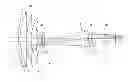
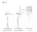
FIG. 1 illustrates a zoom lens system, according to an exemplary embodiment;
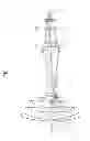
FIG. 2 illustrates a zoom lens system, according to a first exemplary embodiment;
FIG. 3 illustrates longitudinal spherical aberration, astigmatism, and distortion at the wide-mode of the zoom lens system of FIG. 2, according to an exemplary embodiment;
FIG. 4 illustrates comma aberration at the wide-mode of the zoom lens system of FIG. 2, according to an exemplary embodiment;
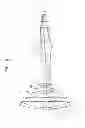
FIG. 5 illustrates a zoom lens system, according to a second exemplary embodiment;
FIG. 6 illustrates longitudinal spherical aberration, astigmatism, and distortion at the wide-mode of the zoom lens system of FIG. 5, according to an exemplary embodiment; and
FIG. 7 illustrates comma aberration at the wide-mode of the zoom lens system of FIG. 5, according to an exemplary embodiment.
DETAILED DESCRIPTION OF THE EXEMPLARY EMBODIMENTS
Hereinafter, the inventive concept will be described more fully with reference to the accompanying drawings, in which exemplary embodiments are shown. The inventive concept may, however, be embodied in many different forms and should not be construed as being limited to the embodiments set forth herein; rather, these embodiments are provided so that this disclosure will be thorough and complete, and will fully convey the inventive concept to those skilled in the art. Unless defined otherwise, technical and scientific terms used herein have the same meaning as is commonly understood by one of skill in the art to which this inventive concept belongs. An expression used in the singular encompasses the expression of the plural, unless it has a clearly different meaning in the context. Also, it is to be understood that the terms such as “comprise” and/or “comprising” are intended to indicate the existence of the features, numbers, steps, actions, components, parts, or combinations thereof, and are not intended to preclude the possibility that one or more other features, numbers, steps, actions, components, parts, or combinations thereof may exist or may be added. Terms such as first, second, etc. may be used to describe various elements, but these terms do not limit elements and are used only to classify one element from another.
FIG. 1 illustrates a zoom lens system, according to an exemplary embodiment.
Referring to FIG. 1, the zoom lens system includes a first lens group G1 having positive refractive power, a second lens group G2 having negative refractive power, a third lens group G3 having positive refractive power, and a fourth lens group G4 having positive refractive power in an order from an object O to an image I. The number of whole lenses may be equal to or less than 10. An aperture ST may be disposed between the second and third lens groups G2 and G3. An optical block corresponding to an optical filter F may be disposed between the fourth lens group G4 and an image plane IP.
The first lens group G1 may include four lenses including a first lens 11, a second lens 12, a third lens 13, and a fourth lens 14. The first lens 11 may be a meniscus lens having negative refractive power and a convex surface facing the object O. The second lens 12 may be a biconvex lens or a plane convex lens having positive refractive power.
The second lens group G2 may include three lenses. The second lens group G2 may include a fifth lens 21, a sixth lens 22, and a seventh lens 23. The fifth lens 21 and the sixth lens 22 may be negative lenses. The seventh lens 23 may be a positive lens.
The third lens group G3 may include at least one aspheric surface. The third lens group G3 may include two lenses including an eighth lens 31 and a ninth lens 32. The eighth lens 31 may have positive refractive power. The ninth lens 32 may include negative refractive power. The eighth lens 31 may have an aspheric surface.
The second lens group G2 and the third lens group G3 may include lenses having a high refractive index, and thus, the zoom lens system having high magnification may be implemented. For example, the second lens group G2 and the third lens group G3 may include lens or lenses having a refractive index equal to or higher than 1.9.
The fourth lens group G4 may include a single lens. For example, the fourth lens group G4 may include a tenth lens 41 having positive refractive power. The fourth lens group G4 includes only the tenth lens 41, and thus, the zoom lens system having a small size and an excellent sensitivity may be implemented. In addition, an assembly tolerance may be reduced when the zoom lens system is assembled, thereby enhancing an assembling property.
The zoom lens system according to the present embodiment may be applied to a photographing apparatus such as a surveillance camera, a still camera, or a video camera. The photographing apparatus may include a solid image sensor device such as a charged coupled device (CCD) or a complementary metal-oxide semiconductor device (CMOS). The solid image sensor device is disposed in the image plane IP of the zoom lens system according to an exemplary embodiment. Light incident from the object O of the zoom lens system may arrive at the image plane IP and may form an image on the solid image sensor device.
The zoom lens system may change a distance between the first through fourth lens groups G1-G4 to perform zooming. During zooming from a wide-mode to a tele-mode (i.e. zooming to high magnification), a distance between the first and second lens groups G1 and G2 may increase, a distance between the second and third lens groups G2 and G3 may decrease, and a distance between the third and fourth lens groups G3 and G4 may decrease and then, increase.
At least two lens groups may move during zooming. During zooming, the first and third lens groups G1 and G3 may be fixed with respect to the image plane IP, and the second and fourth lens groups G2 and G4 may move. The second lens group G2 may move in a direction of an arrow “a” of FIG. 1 to implement magnification, and the fourth lens group G4 may move along a parabolic trace as a direction of an arrow “b” of FIG. 1 to focus and to compensate for lateral chromatic aberration that may be generated during zooming.
The zoom lens system according to an exemplary embodiment may satisfy Conditions below.
The zoom lens system according to an exemplary embodiment may satisfy Condition 1 below:
[Condition 1]
vd—10>75,
where vd—10 denotes an Abbe number of a line d of the tenth lens 41 comprised in the fourth lens group G4, i.e., a chromatic value.
Condition 1 defines the Abbe number of a lens, i.e., the tenth lens 41, included in the fourth lens group G4. If a value of vd—10 is equal to or less than 75, lateral chromatic aberration that may be generated by moving the second lens group G2 during zooming may not be compensated.
Also, the tenth lens 41 may include at least one aspheric surface, and may effectively remove astigmatism that is generated during zooming.
The zoom lens system according to an exemplary embodiment may satisfy Condition 2 below:
65<vd—2<72, [Condition 2]
where vd—2 denotes an Abbe number of a line d of the second lens 12 which is second closer to the object O in the first lens group G1, i.e., a chromatic value.
Condition 2 defines the Abbe number of a lens, i.e., the second lens 12, in the first lens group G1 second closer to the object O. If a value of vd—2 exceeds the above range, chromatic aberration deteriorates. In this case, an additional optical member is necessary for compensating for chromatic aberration, which increases manufacturing costs of the zoom lens system as a whole.
The zoom lens system according to an exemplary embodiment may satisfy Conditions 3-1 and 3-2 below:
vd—3>58; [Condition 3-1]
and
nd—3>1.55, [Condition 3-2]
where vd—3 denotes an Abbe number of a line d of the third lens 13 which is third closer to the object O in the first lens group G1, and nd—3 denotes a refractive index of the line d of the third lens 13 which is third closer to the object O in the first lens group G1.
Conditions 3-1 and 3-2 respectively define the Abbe number and the refractive index of a lens, i.e., the third lens 13, in the first lens group G1 third closer to the object O. If a value of vd—3 is equal to or less than 58, lateral chromatic aberration may not be effectively compensated in the tele-mode. If a value of nd—3 is equal to or less than 1.55, distortion deteriorates.
The zoom lens system according to an exemplary embodiment may satisfy Condition 4 below:
35<Ft/Fw<40, [Condition 4]
where Ft denotes a focal length in the tele-mode of the zoom lens system, and Fw denotes a focal length in the wide-mode of the zoom lens system.
Condition 4 defines magnification of the zoom lens system according to an exemplary embodiment. The zoom lens system according to an exemplary embodiment may provide high magnification in the range from about 35 to about 40 times.
The zoom lens system according to an exemplary embodiment may satisfy Condition 5 below:
1.6≦Fno—w≦1.9, [Condition 5]
where Fno_w denotes an F-number of the zoom lens system in the wide-mode.
The zoom lens system according to an exemplary embodiment may satisfy Condition 6 below:
D16≧1.8 mm, [Condition 6]
where D16 denotes a distance between the eighth lens 31 which is closest to the object O in the third lens group G3 and the ninth lens 32 which is second closer to the object O in the third lens group G3.
If a value of D16 is less than 1.8 mm, since Fno does not satisfy the above range, a generally dark zoom lens system is implemented, and it is difficult to compensate for spheric aberration.
The zoom lens system according to an exemplary embodiment may satisfy Conditions 7-1 and 7-2 below:
Nd—1>1.8; [Condition 7-1]
and
ED—1≦40 mm, [Condition 7-2]
where Nd—1 denotes a refractive index of the first lens 11, and ED—1 denotes an effective diameter of the first lens 11.
Conditions 7-1 and 7-2 respectively define the refractive index and the effective diameter of a lens, i.e., the first lens 11, which is closest to the object O in the first lens group G1. If values of Nd—1 and ED—1 are out of the above ranges, the effective diameter increases, and miniaturization is difficult.
A photographing apparatus, such as a CCTV, not only captures an image during the day, but also at night. In order to obtain a high quality image, the CCTV may include filters suitable for day and night photographing.
The zoom lens system according to an exemplary embodiment may have an overall length in the range from about 81 to about 88, and thus, being miniaturized and provide a back focal length enough to easily exchange an optical member such as a filter.
More specifically, the zoom lens system according to an exemplary embodiment may satisfy Condition 8 below:
4.8 mm≦BFL, [Condition 8-1]
where BFL denotes a back focal length.
Condition 8 defines a back focal length of the zoom lens system. If a value of BFL is smaller than 4.8 mm, in a case where the zoom lens system is applied to the CCTV, a sufficient space necessary for exchanging filters for day and night photographing may not be provided. The optical member such as the filter may not be exchanged, which makes it impossible to perform day or night photographing.
More specifically, BFL may satisfy Condition 8-2 below:
4.8 mm≦BFL≦7.2 mm [Condition 8-2]
If a value of BFL is smaller than 4.8 mm, since the optical member such as the filter may not be exchanged, day or night photographing may be performed. If the value of BFL is greater than 7.2 mm, since the overall length increases, miniaturization is difficult.
Design data of a zoom lens system according to an exemplary embodiment will now be described. The inventive concept is not limited to the embodiment below and may be appropriately modified without departing from the scope thereof.
Hereinafter, R denotes a radius of curvature, Dn denotes a thickness at a center of a lens or an interval between lenses, nd denotes a refractive index of the line d, vd denotes the Abbe number of the line d, and * denotes an aspheric surface.
The aspheric surfaces described above may be defined as follows.
When an optical axis direction is an x-axis, and a direction perpendicular to the optical axis direction is a y-axis, an aspheric shape of a zoom lens according to an exemplary embodiment may be represented by Equation 9 below, where a proceeding direction of the beam is positive. In Equation 9, x denotes a distance from a peak of the zoom lens in the optical axis direction, y denotes a distance from the y-axis in the direction perpendicular to the optical axis direction, k denotes a conic constant, A, B, C, and D each denote an aspheric coefficient, and c denotes an inverse number (1/R) of a radius of curvature at the peak of the zoom lens.
x = cy 2 1 + 1 - ( k + 1 ) c 2 y 2 + Ay 4 + By 6 + Cy 8
First Embodiment
A construction of the zoom lens system based on design data of a first embodiment is illustrated in FIG. 2. Table 1 below shows the design data of the zoom lens system shown in FIG. 2.
Focal length(f)=3.56-128.4 (mm)
Fno=1.715-3.956
| TABLE 1 | ||||
| Surface No. | Rn | Dn | nd | vd |
| S1 | 70.8649 | 1.200 | 1.846663 | 23.78 |
| S2 | 40.6122 | 5.540 | 1.487489 | 70.44 |
| S3 | Infinity | 0.150 | ||
| S4 | 52.4293 | 3.019 | 1.589130 | 61.14 |
| S5 | 190.3664 | 0.150 | ||
| S6 | 27.0098 | 4.166 | 1.496997 | 81.61 |
| S7 | 77.4030 | Variable D7 | ||
| S8 | 54.6512 | 0.550 | 1.910822 | 35.25 |
| S9 | 5.7598 | 3.312 | ||
| S10 | −16.7526 | 0.500 | 1.658436 | 50.85 |
| S11 | 11.6374 | 0.150 | ||
| S12 | 10.2358 | 1.749 | 1.945945 | 17.98 |
| S13 | 49.4851 | Variable D13 | ||
| S14(ST) | Infinity | 0.400 | ||
| *S15 | 9.7582 | 2.690 | 1.693500 | 53.2 |
| *S16 | −80.8777 | 2.429 | ||
| S17 | 12.8082 | 0.500 | 1.945945 | 17.98 |
| S18 | 7.3847 | Variable D18 | ||
| *S19 | 11.8075 | 1.685 | 1.497103 | 81.56 |
| *S20 | −22.6039 | Variable D20 | ||
| S21 | Infinity | 1.900 | ||
| S22 | Infinity | 4.560 | ||
| IP | Infinity | |||
Table 2 shows aspheric coefficients in the zoom lens system of FIG. 1, and Table 3 shows variable distances at the wide-mode, the middle-mode, and the tele-mode.
| TABLE 2 | ||||
| S15 | S16 | S19 | S20 | |
| K | 0 | 0 | 0 | 0 |
| A | −9.3504E−05 | 6.5444E−05 | −3.0722E−04 | −2.1568E−04 |
| B | −8.9388E−07 | −8.6294E−07 | 1.0732E−05 | 8.4720E−06 |
| C | −1.8102E−09 | 1.0374E−08 | −1.1788E−06 | −1.0043E−06 |
| TABLE 3 | ||||
| D7 | D13 | D18 | D20 | |
| Wide-mode | 0.650 | 31.838 | 10.186 | 4.3356 | |
| Middle-mode 1 | 17.603 | 14.885 | 5.5075 | 9.0142 | |
| Middle-mode 2 | 26.556 | 5.933 | 2.8950 | 11.6266 | |
| Tele-mode | 30.488 | 2.000 | 14.3217 | 0.2000 | |
FIG. 3 illustrates longitudinal spherical aberration, astigmatism, and distortion of the zoom lens system of FIG. 2. In a graph regarding a curvature of image field, in an astigmatic field curve, a dotted line denotes tangential astigmatism, and a solid line denotes sagittal astigmatism. The longitudinal spherical aberration is shown with respect to light having wavelengths of about 656.28 nm, about 587.56 nm, about 546.07 nm, about 486.13 nm, and about 435.84 nm, and the astigmatism and the distortion are shown with respect to light having a wavelength of about 546.07 nm.
FIG. 4 illustrates comma aberration. Left graphs show tangential comma aberration, and right graphs show sagittal comma aberration.
Second Embodiment
A construction of the zoom lens system based on design data of the second embodiment is illustrated in FIG. 2. Table 4 below shows the design data of the zoom lens system shown in FIG. 2.
Focal length(f)=3.56-128.3 (mm)
Fno=1.7-3.93
| TABLE 4 | ||||
| Surface No. | Rn | Dn | nd | vd |
| S1 | 70.6812 | 1.200 | 1.846663 | 23.78 |
| S2 | 40.6887 | 5.230 | 1.487489 | 70.44 |
| S3 | −772.3237 | 0.150 | ||
| S4 | 52.2377 | 2.778 | 1.606250 | 63.71 |
| S5 | 149.5270 | 0.150 | ||
| S6 | 26.7653 | 4.154 | 1.496997 | 81.61 |
| S7 | 78.2261 | Variable D7 | ||
| S8 | 29.0772 | 0.550 | 1.910822 | 35.25 |
| S9 | 7.1121 | 3.743 | ||
| S10 | −14.4738 | 0.650 | 1.658436 | 50.85 |
| S11 | 7.8178 | 0.600 | ||
| S12 | 9.2461 | 1.909 | 1.945945 | 17.98 |
| S13 | 27.2049 | Variable D13 | ||
| S14(ST) | Infinity | 0.500 | ||
| *S15 | 11.4086 | 2.457 | 1.693500 | 53.2 |
| *S16 | −50.0070 | 3.779 | ||
| S17 | 20.8411 | 0.500 | 1.945945 | 17.98 |
| S18 | 9.3448 | Variable D18 | ||
| *S19 | 10.3887 | 1.865 | 1.497103 | 81.56 |
| *S20 | −18.8377 | Variable D20 | ||
| S21 | Infinity | 2.010 | BSC7_HOYA | |
| S22 | Infinity | 4.500 | ||
| IP | Infinity | |||
Table 5 shows aspheric coefficients in the zoom lens system of FIG. 5, and Table 6 shows variable distances at the wide-mode, the middle-mode, and the tele-mode.
| TABLE 5 | ||||
| S15 | S16 | S19 | S20 | |
| K | 0 | 0 | 0 | 0 |
| A4 | −3.3075E−05 | 9.8359E−05 | −1.0133E−04 | 3.4947E−05 |
| B | −1.1720E−06 | −8.3109E−07 | 3.8654E−06 | 9.0006E−06 |
| C | 4.9999E−08 | 4.4755E−08 | −1.9447E−07 | −3.5398E−07 |
| TABLE 6 | ||||
| D7 | D13 | D18 | D20 | |
| Wide-mode | 0.700 | 30.538 | 9.171 | 4.6671 | |
| Middle-mode 1 | 24.014 | 7.224 | 2.7000 | 11.1384 | |
| Middle-mode 2 | 27.924 | 3.313 | 6.7682 | 7.0702 | |
| Tele-mode | 29.238 | 2.000 | 13.6384 | 0.2000 | |
FIG. 6 illustrates longitudinal spherical aberration, astigmatism, and distortion of the zoom lens system of FIG. 5. In a graph regarding a curvature of image field, in an astigmatic field curve, a dotted line denotes tangential astigmatism, and a solid line denotes sagittal astigmatism. The longitudinal spherical aberration is shown with respect to light having wavelengths of about 656.28 nm, about 587.56 nm, about 546.07 nm, about 486.13 nm, and about 435.84 nm, and the astigmatism and the distortion are shown with respect to light having a wavelength of about 546.07 nm.
FIG. 7 illustrates comma aberration. Left graphs show tangential comma aberration, and right graphs show sagittal comma aberration.
Table 7 below shows values of Conditions 1 through 8 of the first and second embodiments.
| TABLE 7 | |||||
| Condition | Condition | Condition | Condition | Condition | |
| 1 | 2 | 3-1 | 3-2 | 4 | |
| Embodi- | 81.56 | 70.44 | 61.14 | 1.589130 | 36.07 |
| ment 1 | |||||
| Embodi- | 81.56 | 70.44 | 63.71 | 1.606250 | 36.04 |
| ment 2 | |||||
| Condition | Condition | Condition | Condition | Condition | |
| 5 | 6 | 7-1 | 7-2 | 8 | |
| Embodi- | 1.715 | 2.429 | 1.846663 | 39.8 | 6.6 |
| ment 1 | |||||
| Embodi- | 1.7 | 3.779 | 1.846663 | 39.8 | 6.6 |
| ment 2 | |||||
According to the exemplary embodiments, a zoom lens system having a relatively short overall length even with a small number of lenses, relatively high magnification, and relatively high resolution may be realized.
In addition, the zoom lens system may obtain a sufficiently long BFL, and thus, a filler may be easily exchanged when the zoom lens system is applied to a surveillance camera.
While the inventive concept has been particularly shown and described with reference to exemplary embodiments thereof, it will be understood by those of ordinary skill in the art that various changes in form and details may be made therein without departing from the spirit and scope of the inventive concept as defined by the following claims.
Claims
What is claimed is:1. A zoom lens system comprising, in an order from an object to an image:
a first lens group having positive refractive power;
a second lens group having negative refractive power;
a third lens group having positive refractive power; and
a fourth lens group having positive refractive power,
wherein zooming is performed by changing intervals between the first through fourth lens groups, and a lens included in the fourth lens group satisfies:
vd—10>75,
wherein vd—10 denotes an Abbe number of a line d of the lens included in the fourth lens group.
2. The zoom lens system of claim 1, wherein a second lens second closer to the object in the first lens group satisfies:
65<vd—2<72,
wherein vd—2 denotes an Abbe number of the line d of the second lens.
3. The zoom lens system of claim 1, wherein the fourth lens group comprises a single positive lens, and
wherein vd—10 is an Abbe number of the positive lens of the fourth lens group.
4. The zoom lens system of claim 1, wherein the fourth lens group comprises a single positive lens.
5. The zoom lens system of claim 1, wherein at least one lens included in the fourth lens group comprises an aspheric surface.
6. The zoom lens system of claim 1, satisfying:
35<Ft/Fw<40,
wherein Ft denotes a focal length in a tele-mode of the zoom lens system, and Fw denotes a focal length in a wide-mode of the zoom lens system.
7. The zoom lens system of claim 1, satisfying:
1.6≦Fno—w≦1.9,
wherein Fno_w denotes an F-number of the zoom lens system in the wide-mode.
8. The zoom lens system of claim 1, wherein the third lens group comprises at least two lenses, and a distance between the at least two lenses is equal to or greater than 1.8 mm.
9. The zoom lens system of claim 1, satisfying:
4.8 mm≦BFL,
wherein BFL denotes a back focal length of the zoom lens system.
10. The zoom lens system of claim 1, wherein a first lens closest to the object in the first lens group satisfies:
Nd—1≧1.8;
and
ED—1≦40 mm,
wherein Nd—1 denotes a refractive index of the first lens, and ED—1 denotes an effective diameter of the first lens.
11. The zoom lens system of claim 1, wherein a third lens third closer to the object in the first lens group satisfies:
vd—3>58;
and
nd—3>1.55,
wherein vd—3 denotes an Abbe number of the line d of the third lens, and nd—3 denotes a refractive index of the line d of the third lens.
12. The zoom lens system of claim 1, wherein the fourth lens group and the fourth lens group move during zooming, and the first lens group and the third lens group are fixed.
13. The zoom lens system of claim 1, wherein the third lens group comprises a positive lens and a negative lens in the order from the object.
14. The zoom lens system of claim 13, wherein a third lens closest to the object included in the third lens group comprises at least one aspheric surface.
15. The zoom lens system of claim 1, wherein the second lens group and the third lens group comprise lenses having a refractive index greater than 1.9.
16. A zoom lens system comprising, in an order from an object to an image:
a first lens group having positive refractive power;
a second lens group having negative refractive power;
a third lens group having positive refractive power; and
a fourth lens group having positive refractive power,
wherein zooming is performed by changing intervals between the first through fourth lens groups, and a total number of lenses forming the first through fourth lens groups is less than or equal to 10.
17. The zoom lens system of claim 16, wherein the fourth lens group comprises a single positive lens.
18. The zoom lens system of claim 17, wherein the single positive lens comprises an aspheric surface.
19. The zoom lens system of claim 16, wherein a lens included in the fourth lens group satisfies:
vd—10>75,
wherein vd—10 denotes an Abbe number of a line d of the lens included in the fourth lens group.
20. The zoom lens system of claim 16, satisfying:
35<Ft/Fw<40,
wherein Ft denotes a focal length in a tele-mode of the zoom lens system, and Fw denotes a focal length in a wide-mode of the zoom lens system.
Images & Drawings included:


Sources:
- United States Patent and Trademark Office - verify current appl. status at the USPTO↗
Similar patent applications:
- » 20170242227
Zoom lens system, interchangeable lens device and camera system with zoom lens system, and imaging apparatus with zoom lens system - » 20090161229
Zoom lens system, optical device with zoom lens system, and method of manufacturing zoom lens system - » 20110096409
Zoom lens system, optical device with zoom lens system, and method of manufacturing zoom lens system - » 20110141575
Zoom lens system, optical apparatus equipped with zoom lens system and method for zooming zoom lens system - » 20090147376
Zoom lens system, optical device with zoom lens system, and method of manufacturing zoom lens system - » 20090244720
Zoom lens system, optical device with the zoom lens system, and method of manufacturing the zoom lens system - » 20130120854
Zoom lens system, optical device with the zoom lens system, and method of manufacturing the zoom lens system - » 20110228406
Zoom lens system, optical device with the zoom lens system, and method of manufacturing the zoom lens system - » 20080198476
Zoom lens system and camera including zoom lens system - » 20180326909
Zoom lens system, imaging device having zoom lens system, and vehicle having imaging device
Recent applications in this class:
- » 20250224598 2025-07-10
OPTICAL SYSTEM, LENS APPARATUS, AND IMAGE PICKUP APPARATUS - » 20250138291 2025-05-01
ZOOM OPTICAL SYSTEM - » 20250085518 2025-03-13
ZOOM OPTICAL SYSTEM, OPTICAL APPARATUS AND METHOD FOR MANUFACTURING THE ZOOM OPTICAL SYSTEM - » 20230176345 2023-06-08
Zoom optical system - » 20230008842 2023-01-12
PROJECTION SYSTEM AND METHOD WITH MODULAR PROJECTION LENS - » 20230003981 2023-01-05
SYSTEM AND METHOD FOR ELECTRONIC CORRECTION OF BORESIGHT ERRORS IN VARIABLE MAGNIFICATION OPTICAL SYSTEMS - » 20220299741 2022-09-22
OPTICAL SYSTEM, LENS APPARATUS, AND IMAGE PICKUP APPARATUS - » 20220099950 2022-03-31
Lens Device - » 20210349292 2021-11-11
Plastic barrel, autofocus module and electronic device - » 20200371323 2020-11-26
Camera and Lens Systems Using Off-Axis Free Form Elements and Methods Therefor
Recent applications for this Assignee:
- » 20190182425 2019-06-13
Method of maintaining tilt angle, method of controlling tilting, and surveillance camera - » 20190132523 2019-05-02
Monitoring apparatus and system - » 20190082146 2019-03-14
Surveillance system and method of operating surveillance system - » 20190079832 2019-03-14
Data distribution storing method and system thereof - » 20190056571 2019-02-21
Zoom lens system - » 20190020821 2019-01-17
Image stabilizing method and apparatus - » 20180373894 2018-12-27
DIGITAL FORENSIC IMAGE VERIFICATION SYSTEM - » 20180324024 2018-11-08
Device, system, and method to perform real-time communication - » 20180285680 2018-10-04
Method and apparatus for detecting fog from image - » 20180276778 2018-09-27
Duplicate image evidence management system for verifying authenticity and integrity