Restraining flaps of an insert
US20140196409A1
2014-07-17
13/708,841
2013-01-15
✅ Patent granted
US 10,071,827 B2
2018-09-11
-
-
Stephen F Gerrity
Sam Silverberg
2035-06-22
Abstract:
The invention is directed to solving the problem of wrapping a bundle with cardboard without using glue to hold the cardboard flaps in place before wrapping the bundle with a heat shrink film. The problem is solved by using a mechanical fly bars to restrain the flaps of an insert while moving a bundle on a conveyor. The insert can be any material that provides structural protection to the bundle during stacking.
Inventors:
- Alain Serf 1 🇺🇸 N. Redington Beach, FL, United States
- Alain Cerf 2 🇺🇸 N. Redington Beach, FL, United States
Applicant:
Interested in similar patents?
Get notified when new applications in this technology area are published.
Classification:
B65B11/06 » CPC main
Wrapping, e.g. partially or wholly enclosing, articles or quantities of material, in strips, sheets or blanks, of flexible material Wrapping articles, or quantities of material, by conveying wrapper and contents in common defined paths
B65B9/026 » CPC further
Enclosing successive articles, or quantities of material, e.g. liquids or semiliquids, in flat, folded, or tubular webs of flexible sheet material; Subdividing filled flexible tubes to form packages; Enclosing successive articles, or quantities of material between opposed webs the webs forming a curtain
B65B35/243 » CPC further
Supplying, feeding, arranging or orientating articles to be packaged; Feeding, e.g. conveying, single articles by endless belts or chains using cooperating conveyors engaging the articles simultaneously
B65B11/58 » CPC main
Wrapping, e.g. partially or wholly enclosing, articles or quantities of material, in strips, sheets or blanks, of flexible material Applying two or more wrappers, e.g. in succession
B65B9/02 IPC
Enclosing successive articles, or quantities of material, e.g. liquids or semiliquids, in flat, folded, or tubular webs of flexible sheet material; Subdividing filled flexible tubes to form packages Enclosing successive articles, or quantities of material between opposed webs
B65B53/02 » CPC further
Shrinking wrappers, containers, or container covers during or after packaging by heat
B65B61/22 » CPC further
Auxiliary devices, not otherwise provided for, for operating on sheets, blanks, webs, binding material, containers or packages for adding cards, coupons or other inserts to package contents for placing protecting sheets, plugs, or wads over contents, e.g. cotton-wool in bottles of pills
B65B35/24 IPC
Supplying, feeding, arranging or orientating articles to be packaged; Feeding, e.g. conveying, single articles by endless belts or chains
B65B11/10 » CPC further
Wrapping, e.g. partially or wholly enclosing, articles or quantities of material, in strips, sheets or blanks, of flexible material; Wrapping articles, or quantities of material, by conveying wrapper and contents in common defined paths in a single straight path to fold the wrappers in tubular form about contents
Description
FIELD OF THE INVENTION
This invention relates to wrapping a cardboard around an article or a bundle of articles to provide structural support to the article or bundle to prevent crushing of the article.
BACKGROUND OF THE INVENTION
Packaging bundles on a pallets required placing the bundles in a box to prevent the bundles from being crushed during stacking. Using cardboard box increased the cost of the manufacturing. This created a need to provide a bundle to that was more resistant to crushing that be packaged on a pallet without the need for a cardboard box.
The use of cardboard inserts to provide structural integrity to a bundle was described in U.S. patent application Ser. No. 13/453,931 filed on Apr. 23, 2012. The inventor was Alain Cerf. This application is incorporated by reference in its entirety. U.S. Pat. No. 5,934,049 filed on Aug. 10, 1999 is incorporated by reference in its entirety.
SUMMARY OF THE INVENTION
One of the objectives of the invention is to resolve the problem of wrapping a bundle with cardboard without using glue to hold the cardboard flaps in place before wrapping the bundle with a heat shrink film. A bundle is defined a single article or a collection of articles. By eliminating the gluing of the cardboard, a heat shrink machine can operate at a faster speed. Another objective of the invention is to use two U shaped cardboard as described in the above application. This alleviates the problem associated with using a single large piece of cardboard to provide stacking support for a large bundle. Another objective is to use an insert where the bundle is placed on the insert and the flaps of the insert are pressed against the bundle. The objectives of this invention are achieved by restraining the flaps surrounding the bundle while traveling on a conveyor prior to film wrapping the bundle and heat shrinking the film.
BRIEF DESCRIPTION OF THE DRAWINGS
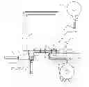
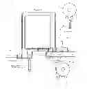
FIG. 1 shows a bundle wherein the flaps of the bundle are restrained from moving by flying bars.
FIG. 2 shows a bundle being placed in a bucket conveyor so that the bundle rests on the film.
FIG. 3 shows an insert for a bundle.
DETAILED DESCRIPTION OF THE INVENTION
An article or a bundle of articles 4 having a u shaped cardboard at each or end of the article or a cardboard insert that provides structural support to a bundle is placed on a dead plate 6 located substantially parallel to bucket conveyor 9. The plate is slightly above elements 10 and 11 and extends as close as possible to element 11 to facilitate the placement of the bundle in the buckets defined by elements 10 and 11.
A pusher 12 moves a collated bundle 4, having guides 14 to hold the flaps in place, on a plate 3 to an elevator 5. When the flying conveyors are substantially stopped or stopped, the elevator 5 lifts the collated bundle 4 through vertical transfer guides to substantially the same level as the dead plate 6 so that the bundle is between flying bars 7 and 8. The vertical transfer guides 15 maintain the flaps in a restrained position.
Flying bar 7 travels on flying bar conveyor 9. Flying bar 8 travels on flying bar conveyor 10. The position of the flying bars can be adjusted to accommodate the size of the bundle. After the bundle is placed between the flying bars 7 and 8, the flying conveyors begin to move causing flying bar 8 to push against the bundle. Fly bar 8 moves the bundle on the dead plate toward bucket package conveyor 16 while the fly bars 7 and 8 prevent the flaps from opening away from the bundle. The movement of fly bar conveyors is synchronized with the movement with the bucket conveyor 9. The bucket conveyor is moving at the same speed as the flying bar conveyors. The bundle is pushed off the dead plate by fly bar 8. Fly bar conveyors are arranged so that fly bars 7 and 8 guide the bundle off the dead plate into the bucket. When the flying bars 7 and 8 releases the bundle as the flying bars move up, the bucket conveyor stops and a bucket is positioned underneath the bundle to receive the bundle. Elements 10 and 11 which can be the sides of the bucket restrain the flaps of the bundle when the bundle rests in the bucket. Once the fly bars clear the height of the bundle, the flying bar conveyors stop and a new bundle on elevator 5 is inserted between fly bars 7 and 8. After the bundle is inserted between fly bars 7 and 8, the fly bar conveyors and bucket conveyor restart the cycle. If there is no product available to be placed in the bucket, only the bucket conveyor will move.
The heat shrink film 17 comes off roll 18 and is threaded so that film covers the bucket so that when the bundle is placed on the bucket, the bundle rests on the film. The film continues in a substantial vertical direction onto roll 21 so that the bundle can push against the plane of the film causing the film to wrap around the bundle. As the bundle passes the sealing bar 19, the sealing bar comes down and heat seals and cuts the film thereby presenting the next bundle a continuous plane of film for wrapping.
Claims
1. An apparatus for transporting a bundle having an insert with flaps to provide structural integrity to the bundle while mechanically restraining the flaps of the insert while moving the bundle on a conveyor comprising,
means for moving the bundle wherein the flaps of an insert are mechanically restrained.,
means for transporting the bundle onto a film wrapping conveyor while restraining the movement of the flaps, and
means for film wrapping the bundle while on said film wrapping conveyor.
2. An apparatus according to claim 1 wherein the means for moving the bundle includes pushing the bundle on a dead plate.
3. An apparatus according to claim 2 where in the bundle is pushed by a first fly bar attached to a first fly bar conveyor.
4. An apparatus according to claim 3 wherein a second fly bar attached to a second fly bar conveyor acts together with the first fly bar to restrain the movement of the flaps while the bundle is being moved.
5. An apparatus according to claim 4 wherein the film wrapping conveyor has buckets to receive the bundle and to restrain the movements of the flaps.
6. An apparatus according to claim 5 where the means for film wrapping includes a film threaded over the bucket and for providing a plane of film so that the bundle pushes into the plane causing the film to cover the bundle.
7. An apparatus according to claim 6 wherein a sealing bar heat seals the film around the bundle and cuts the film to maintain the plane of the film so that the next bundle can be wrapped.
8. An apparatus according to claim 7 including means for stopping the bucket conveyor when the first and second fly bar release the bundle and the bucket is positioned under the bundle.
9. An apparatus according to claim 8 including means for stopping the fly bar conveyors after the first and second fly bars clear the height of the bundle
10. An apparatus according to claim 9 including means for moving a bundle between a another pair of fly bars while the fly bar conveyors are stopped.
11. A process for transporting a bundle having an insert with flaps to provide structural integrity to the bundle while mechanically restraining the flaps of the insert while moving the bundle on a conveyor comprising,
moving the bundle wherein the flaps of an insert are mechanically restrained.,
transporting the bundle onto a film wrapping conveyor while restraining the movement of the flaps, and
film wrapping the bundle while on said film wrapping conveyor.
12. A process according to claim 11 wherein moving the bundle includes pushing the bundle on a dead plate.
13. A process of according to claim 12 where a first fly bar attached to a first fly bar conveyor pushes the bundle.
14. A process according to claim 13 includes restraining the flaps of the moving bundle by using a second fly bar attached to a second fly bar conveyor.
15. A process according to claim 14, including providing a film wrapping conveyor having buckets to receive the bundle and to restrain the movements of the flaps.
16. A process according to claim 15 including threading the heat shrink film over the bucket so that the bundle can be placed in bucket and rest on the film.
17. A process according to 16 including providing a plane of film and pushing the bundle into the plane causing the film to cover the bundle.
18. A process according to claim 17 including stopping the bucket conveyor when a bucket is positioned to receive a bundle being released by the first and second fly bars.
19. A process according to claim 18 including stopping the fly bar conveyors after the first and second fly bars clear the height of the bundle.
20. A process according to claim 19 including moving a bundle between another pair of fly bars when the fly bar conveyors are stopped.
Images & Drawings included:


Sources:
- United States Patent and Trademark Office - verify current appl. status at the USPTO↗
Recent applications in this class:
- » 20230365283 2023-11-16
PAPER-BASED MULTILAYER PACKAGING MATERIALS AND METHODS - » 20180229868 2018-08-16
Packaging kit, package, packaging method using packaging kit, packaging kit manufacturing apparatus, and packaging kit manufacturing method - » 20170190449 2017-07-06
PACKAGING MACHINE FOR PACKAGES WITH AN L-BOARD - » 20160318638 2016-11-03
Apparatus and Method of Using an Apparatus for Controlling a Film - » 20150353215 2015-12-10
MEMBRANE STRAPPING APPARATUS - » 20140096478 2014-04-10
Method and system for dynamically adjusting the relative position of internal content material in a mailpiece fabrication system - » 20140033656 2014-02-06
APPARATUS, SYSTEM & METHOD FOR ADJUSTABLE WRAPPING - » 20130340392 2013-12-26
Supply group of a packing band from reels, with an automatic change of the reel, for object-packing machines - » 20130318914 2013-12-05
AUTOMATIC PACKAGING DEVICE - » 20130298498 2013-11-14
PACKAGING DEVICE