Photoelectric coupling module with fiber module connected to lens module by positioning pole
US20140199031A1
2014-07-17
13/968,403
2013-08-15
✅ Patent granted
US 9,229,178 B2
2016-01-05
-
-
Akm Enaeyt Ullah
Novak Druce Connolly Bove + Quigg LLP
2033-12-08
Abstract:
A photoelectric coupling module includes a fiber module and a lens module. The fiber module defines a number of receiving holes and at least one positioning hole. The lens module includes a main body and at least one positioning pole. The main body includes a lens portion and a receiving portion. The lens portion includes a central portion and an edge portion surrounding the central portion, the central portion includes a plurality of lenses. The receiving portion is positioned on the edge portion. The at least one positioning pole is received in the receiving portion, and is positioned on the edge portion. One end of the fiber module is received in the receiving portion. The at least one positioning pole is received in the at least one positioning hole, and the lenses are aligned with the receiving holes.
Assignee:
- HON HAI PRECISION INDUSTRY CO., LTD. 10,014 🇹🇼 New Taipei, Taiwan
Applicant:
Interested in similar patents?
Get notified when new applications in this technology area are published.
Classification:
G02B6/3616 » CPC main
Light guides; Coupling light guides; Mechanical coupling means Holders, macro size fixtures for mechanically holding or positioning fibres, e.g. on an optical bench
G02B6/36 IPC
Light guides; Coupling light guides Mechanical coupling means
G02B6/32 » CPC further
Light guides; Coupling light guides; Optical coupling means having lens focusing means positioned between opposed fibre ends
G02B6/3885 » CPC further
Light guides; Coupling light guides; Mechanical coupling means having fibre to fibre mating means; Dismountable connectors, i.e. comprising plugs; Connectors using guide surfaces for aligning ferrule ends, e.g. tubes, sleeves, V-grooves, rods, pins, balls Multicore or multichannel optical connectors, i.e. one single ferrule containing more than one fibre, e.g. ribbon type
G02B6/4204 » CPC main
Light guides; Coupling light guides; Coupling light guides with opto-electronic elements; Packages, e.g. shape, construction, internal or external details the coupling comprising intermediate optical elements, e.g. lenses, holograms
G02B6/4292 » CPC further
Light guides; Coupling light guides; Coupling light guides with opto-electronic elements the light guide being disconnectable from the opto-electronic element, e.g. mutually self aligning arrangements
G02B6/42 IPC
Light guides; Coupling light guides Coupling light guides with opto-electronic elements
G02B6/38 IPC
Light guides; Coupling light guides; Mechanical coupling means having fibre to fibre mating means
Description
BACKGROUND
1. Technical Field
The present disclosure relates to photoelectric technologies and, particularly, to a photoelectric coupling module.
2. Description of Related Art
Photoelectric coupling modules generally include a fiber module and a lens module coupled to the fiber module. The fiber module defines at least one positioning hole. The lens module includes a main body and at least one positioning pole extending outward from the main body. The positioning pole is received in the positioning hole to ensure a coupling accuracy of the fiber module and the lens module. However, as the positioning pole protrudes outward from the main body, and may be easily broke from the main body, which results in the stability of the photoelectric coupling module is decreased.
Therefore, it is desirable to provide a photoelectric coupling module, which can overcome the limitations described.
BRIEF DESCRIPTION OF THE DRAWINGS
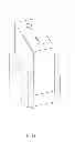
FIG. 1 is a schematic view of a photoelectric coupling module in accordance with an exemplary embodiment.
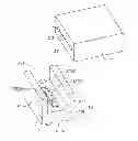
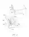
FIG. 2 is an isometric, exploded, and schematic view of the photoelectric coupling module of FIG. 1.
DETAILED DESCRIPTION
Embodiments of the disclosure will be described with reference to the drawings.
FIGS. 1-2 show a photoelectric coupling module 10, according to an exemplary embodiment. The photoelectric coupling module 10 includes a fiber module 11 and a lens module 12.
The fiber module 11 is a cuboid, and is made of plastic material. The fiber module 11 is integrally molded. The fiber module 11 includes a front surface 111 and a rear surface 112 opposite to the front surface 111. The fiber module 11 defines a number of receiving holes 113 running through the front surface 111 and the rear surface 112, and at least one positioning hole 114 in the rear surface 112.
The receiving holes 113 are substantially parallel with each other and perpendicular to the front surface 111 and the rear surface 112. The receiving holes 113 are linearly and equidistantly arranged. The receiving holes 113 are used for receiving optical fibers (not shown). The positioning hole 114 is parallel to the receiving hole 113. In the embodiment, the number of the positioning holes 114 is two and the positioning holes 114 are adjacent to two opposite sides of the fiber module 11. The receiving holes 113 are positioned between the two positioning holes 114. The positioning holes 114 can be through holes or blind holes. An internal diameter of the positioning holes 114 is greater than an internal diameter of the receiving hole 113.
The lens module 12 is a cuboid, and is made of plastic material. The lens module 12 is integrally molded. The lens module 12 includes a main body 121 and at least one positioning pole 122. The main body 121 includes a lens portion 123 and a receiving portion 124. The lens portion 123 includes a central portion 1231 and an edge portion 1232 surrounding the central portion 1231. A thickness of the central portion 1231 is less than a thickness of the edge portion 1232. The central portion 1231 includes a number of lenses 1233. The lenses 1233 are substantially linearly arranged. The number of the lenses 1233 corresponds to the number of the receiving holes 113.
The edge portion 1232 includes a supporting surface 1234. The receiving portion 124 includes a receiving room 1241, and is positioned on the supporting surface 1234. A size of a cross-sectional surface of the receiving room 1241 is slightly greater than a cross-sectional surface of the fiber module 11. In the embodiment, the holding portion 124 includes two positioning plates 1241. The two positioning plates 1241 are opposite to each other. The at least one positioning pole 122 is positioned on the supporting surface 1234, and is received in receiving room 1241. An external diameter of the positioning pole 122 is substantially equal to an internal diameter of the positioning hole 114. In the embodiment, the number of the positioning poles 122 is two. The lenses 1233 are arranged between the two positioning poles 122.
In assembly, one end of the fiber module 11 is received in the receiving room 1241 of the receiving portion 124. The positioning poles 122 are received in the positioning holes 114. The lenses 1233 of the lens module 12 are respectively aligned with the receiving holes 113 of the fiber module 11.
In use, light rays projected on the lenses 1233 are converged by the lenses 1233, and then emit into the optical fibers received in the receiving hole 113. Light rays emitted from the optical fibers are projected to the lenses 1233, the lenses 1231 converge the light rays to a photo diode (not shown).
In the embodiment, as one end of the fiber module 11 is received in the receiving room 1241 of the receiving portion 124, the positioning poles 122 will be harder break from the main body 121. Therefore, the stability of the photoelectric coupling module 10 is increased.
Particular embodiments are shown and are described by way of illustration only. The principles and the features of the present disclosure may be employed in various and numerous embodiments thereof without departing from the scope of the disclosure as claimed. The above-described embodiments illustrate the scope of the disclosure but do not restrict the scope of the disclosure.
Claims
What is claimed is:1. A photoelectric coupling module, comprising:
a fiber module defining a plurality of receiving holes and at least one positioning hole; and
a lens module, comprising:
a main body comprising a lens portion and a receiving portion, the lens portion comprising a central portion and an edge portion surrounding the central portion, the central portion comprising a plurality of lenses, the receiving portion positioned on the edge portion;
at least one positioning pole received in the receiving portion and positioned on the edge portion;
wherein one end of the fiber module is received in the receiving portion, the at least one positioning pole is received in the at least one positioning hole, and the lenses are aligned with the receiving holes.
2. The photoelectric coupling module of claim 1, wherein the fiber module comprises a front surface and a rear surface opposite to the front surface, the receiving holes run through the front surface and the rear surface, the at least one positioning hole is defined in the rear surface.
3. The photoelectric coupling module of claim 2, wherein the receiving holes are substantially parallel with each other and perpendicular to the front surface and the rear surface, the receiving holes are linearly and equidistantly arranged.
4. The photoelectric coupling module of claim 3, wherein the at least one positioning hole is parallel to the receiving holes, the number of the at least one positioning holes is two and the two positioning holes are positioned adjacent to two opposite sides of the fiber module, the receiving holes are positioned between the two positioning holes.
5. The photoelectric coupling module of claim 1, wherein the receiving portion comprises a receiving room, one end of the fiber module is received in the receiving room.
6. The photoelectric coupling module of claim 1, wherein the edge portion comprises a supporting surface, the receiving portion and the at least one positioning pole are positioned on the supporting surface.
7. The photoelectric coupling module of claim 6, wherein the receiving portion comprises two positioning plates oppositely positioned on the supporting surface, and one end of the fiber module is received between the two positioning plates.
8. The photoelectric coupling module of claim 1, wherein an external diameter of the at least one positioning pole is substantially equal to an internal diameter of the at least one positioning hole.
9. The photoelectric coupling module of claim 1, wherein the number of the at least one positioning pole is two, the lenses are arranged between the two positioning poles.
Images & Drawings included:
Sources:
- United States Patent and Trademark Office - verify current appl. status at the USPTO↗
Recent applications in this class:
- » 20250277939 2025-09-04
SPACER AND SPACER STRUCTURE - » 20250199246 2025-06-19
SYSTEMS AND METHODS FOR VIBRATION DAMPING IN MULTI-FIBER CONNECTORS - » 20250180816 2025-06-05
FIBER ROUTING ARRANGEMENT STRUCTURALLY CONFIGURED TO PROVIDE ROUTING FOR OPTICAL FIBERS IN A FIBER MANAGEMENT SYSTEM SO AS TO ENHANCE EXPANSION OF THE FIBER MANAGEMENT SYSTEM - » 20250180815 2025-06-05
ROTATABLE CABLE GUIDE FOR A TRAY ASSEMBLY OF A NETWORK RACK AND METHOD OF USING SAME - » 20250172759 2025-05-29
APPARATUS, SYSTEM, AND METHOD OF PROVIDING A TRAY FOR HOLDING AN OPTOELECTRONIC DEVICE DURING PRINTED CIRCUIT BOARD MANUFACTURING - » 20250138247 2025-05-01
FRAME ASSEMBLIES FOR OPTICAL FIBER DISTRIBUTION ELEMENTS - » 20250093586 2025-03-20
METHOD FOR CONNECTING OPTICAL WAVEGUIDE AND OPTICAL WAVEGUIDE CONNECTION DEVICE - » 20250044522 2025-02-06
APPARATUS FOR ALIGNING MULTIPLE FIBERS - » 20250035855 2025-01-30
FIBER WIRE FIXATION STRUCTURE, OPTICAL SUBMARINE REPEATER, AND METHOD OF ASSEMBLING FIBER WIRE FIXATION STRUCTURE - » 20250012978 2025-01-09
FIBER OPTIC ADAPTER HOLDER; ASSEMBLY; AND METHOD
Recent applications for this Assignee:
- » 20250218287 2025-07-03
METHOD OF GENERATING AND PROMPTING TRAFFIC INFORMATION, AND ROADSIDE DEVICE THEREOF - » 20250178535 2025-06-05
METHOD FOR CONSTRUCTING 3D PANORAMIC VIEW MODEL, VEHICLE-MOUNTED DEVICE, AND STORAGE MEDIUM - » 20250074444 2025-03-06
METHOD FOR EARLY WARNING A BLIND AREA, ELECTRONIC DEVICE AND STORAGE MEDIUM - » 20240416754 2024-12-19
DISPLAY CONTROL DEVICE, DISPLAY EQUIPMENT, AND VEHICLE EMPLOYING DEVICE - » 20240411051 2024-12-12
Light-emitting device array and optical transceiver system having the same - » 20240324114 2024-09-26
DISPLAY CONTROL DEVICE AND VEHICLE EMPLOYING DEVICE - » 20240295957 2024-09-05
METHOD FOR CONTROLLING ELECTRONIC DEVICE, ELECTRONIC DEVICE AND COMPUTER STROAGE MEDIUM EMPLOYING METHOD - » 20240257357 2024-08-01
METHOD FOR DETECTING OBSTACLES, ELECTRONIC DEVICE, AND STORAGE MEDIUM - » 20240203133 2024-06-20
LANE LINE RECOGNITION METHOD, ELECTRONIC DEVICE AND STORAGE MEDIUM - » 20240194999 2024-06-13
Robot using limiting device for locking battery