Automatically adjusting light shelf and method of use
US20140203166A1
2014-07-24
13/745,779
2013-01-19
✅ Patent granted
US 9,188,658 B2
2015-11-17
-
-
Francis M Legasse, Jr.
MU Patents | Timothy Marc Shropshire | Garrett James O'Sullivan
2033-06-23
Abstract:
One embodiment of a microcontroller (24) connected to light sensors (12) that measure the light conditions within a space to determine whether a light shelf (10) should be rotated about a hinge (20) automatically by a servomotor (18) in order to provide the most advantageous use of daylighting.
Inventors:
- Trevor Scott Betz 1 🇺🇸 Belleville, MI, United States
- Trevor Scott Betz 1 🇺🇸 Ann Arbor, MI, United States
Applicant:
Interested in similar patents?
Get notified when new applications in this technology area are published.
Classification:
G01J1/20 » CPC main
Photometry, e.g. photographic exposure meter by comparison with reference light or electric value provisionally void intensity of the measured or reference value being varied to equalise their effects at the detectors, e.g. by varying incidence angle
G01S3/784 » CPC main
Direction-finders for determining the direction from which infrasonic, sonic, ultrasonic, or electromagnetic waves, or particle emission, not having a directional significance, are being received using electromagnetic waves other than radio waves; Systems for determining direction or deviation from predetermined direction using amplitude comparison of signals derived from static detectors or detector systems using a mosaic of detectors
F21S11/00 IPC
Non-electric lighting
F21S11/00 IPC
Non-electric lighting devices or systems using daylight
F21S11/007 » CPC further
Non-electric lighting devices or systems using daylight characterised by the means for transmitting light into the interior of a building
H02S20/32 » CPC further
Supporting structures for PV modules; Supporting structures being movable or adjustable, e.g. for angle adjustment specially adapted for solar tracking
Description
CROSS-REFERENCE TO RELATED APPLICATIONS
The following is a tabulation of some prior art that presently appears relevant:
| U.S. Patents |
| Pat. No. | Kind Code | Issue Date | Patentee |
| 4,013,885 | A1 | 1977-03-22 | Blitz, D |
| 4,225,781 | A1 | 1980-09-30 | Hammones, B |
| 4,349,733 | A1 | 1982-09-14 | Beam, B |
| 6,988,525 | A1 | 2004-12-23 | Moulton, P |
| 7,417,397 | A1 | 2009-01-22 | Berman, J |
| 8,116,004 | A1 | 2010-10-07 | Griffiths, R |
| 12/421,967 | A1 | 2010-10-14 | Hyatt, L |
BACKGROUND
Prior-Art
As world populations grow and put a greater strain on the availability of resources there is an increasingly focused effort on sustainable, energy efficient designs, particularly when it comes to architecture, as buildings are the single largest user of energy within the United States. Although the specific energy profile of a building depends largely on its particular use, space lighting consistently ranks within the top slots of energy expenditure. While lighting technology continues to advance and produce more efficient means of artificial lighting, no fixture will ever be able to overtake the innate sustainable features of properly exploited natural light within a structure.
One area of lighting design that has been able to effectively exploit natural daylight is the use of light shelves. A light shelf is essentially a horizontal opaque surface mounted to a window frame, where a portion of the window glazing extends above the light shelf. The diffuse or specular surface of the light shelf effectively reflects the sunlight to the upper regions of the room. If the ceiling is designed with a sufficient reflectivity, the light is then redirected to the workspace as free area lighting, whereas a design without light shelves would have the sunlight instead absorbed by the carpet. By combining the window fenestration with a shading element below the light shelf, free daylighting can be harvested while still avoiding unnecessary glare.
Some of the current designs, such as U.S. Pat. No. 8,116,004 by Griffiths R. T., approach the manufacturability and design deficiencies as a means to broaden the use of light shelves. Such designs do address the manufactured surface of the light shelf as a means of controlling the availability of light, but do little to have any automatic control as a means of compensating for differing lighting conditions.
One of the drawbacks of light shelves is their inability to adjust to differing lighting conditions to maximize their effect. In the mid to extreme latitudes, the sun's angle to the horizon changes throughout the seasons which can affect how the light is reflected into the space. For example, in the winter when the sun is at a low relative angle, the daylight would be reflected at a relatively small angle of incidence having the effect of the daylighting maximized deep within the space. Conversely, in the summer when the sun is at a high angle, most of the light would be reflected to an area near the window leaving the interior spaces with less than optimal daylighting.
There have been some attempts to remedy this effect on a light shelf. U.S. Pat. No. 6,988,525 by Mouton P., explains an adjustable light shelf design. However, there are no automatic controls present in this apparatus. Whenever it is left to an occupant to manually adjust an apparatus, the operation typically deviates from the optimum as the person may not always be cognizant of the need to adjust the device, and furthermore, may not be able to take time away from the present task to do so. This invariably lends itself to sub-optimal operation and often means the apparatus is left in a more disadvantageous position than if the adjustment option was excluded. There are methods of automatic shade controls, such as U.S. Pat. No. 7,417,397 by Berman et. Al., but this is not intended for use with light shelves. While this patent uses sensors and a controller, its aim is to provide shade position to facilitate a desired light level within the space. Since it is not used with light shelves, the direction of the light entering the space is not controlled into the most advantageous spot to be used by the workspace. This can lead to various lighting conditions throughout the sun's position, which may lead to artificial lighting being used even when there is sufficient daylighting available. In fact, many audits show that occupants will unwittingly subject themselves to overlit conditions in order to even out the lighting throughout the space. There are some light shelf devices, such as the one detailed by U.S. Pat. No. 8,116,004 by Griffiths, that details a light shelf system but does not have an adequate means of automatically orienting the device for the preferred lighting condition. Other designs, such as U.S. patent application Ser. No. 12/421,967 by Hyatt, feature adjustable light shelves but they are manual designs specified to simply enhance the robustness of the shelf and not for optimizing interior lighting.
There are other devices not specifically used for light shelves that have reorienting methods that respond to sunlight but are not particularly well suited to light shelf applications. U.S. Pat. No. 4,013,885 by Blitz is a sun tracker that uses an imaging tracker located directly behind the collecting device that would be awkwardly placed within the living space if used in a light shelf application. U.S. Pat. No. 4,225,781 by Hammonds uses a pyramid-shaped array of sensors that would not work well for a light shelf application, which necessitates the sensors being on the same plane such as on a ceiling in the preferred embodiment. U.S. Pat. No. 4,349,733 by Beam details a sun tracker that uses a means of orientation that seeks uniformly illuminated photo sensors, while the differential method used in this device makes it easier to orient the device to maximize light in the most advantageous point in the space by placing the central sensor where the maximum light point is desired, as opposed to manipulating all of the sensor locations so that they are equally illuminated when the light is in the proper placement. None of the above devices in this paragraph utilizes a clock function to determine preferred no operating times, nor do they apply to light shelves.
Other embodiments could be useful for other purposes than architectural space lighting. This could include any apparatus that requires directed daylight on a specific point regardless of source orientation to the reflective surface. An example could be a solar thermal application where the light is required to be continuously focused on a specific area that needs heating, or a solar application where reflected light is used by photovoltaic cells to produce electricity.
SUMMARY
In accordance with one embodiment, an automatically adjusting light shelf comprises of a light shelf, a plurality of light sensors, an astronomical clock, a servomotor, an override switch, and a microcontroller.
Accordingly, several advantages of one or more aspects are as follows: to provide an automatically adjusting light shelf, that uses a plurality of light shelves to communicate with a servomotor via a microcontroller to find the best rotational angle of the light shelf as a means of optimizing the placement of the light reflected off of the light shelf surface, an astronomical clock that utilizes an algorithm to determine the optimal operating times, and a switch that will allow an end-user the option to override predetermined operation. Other advantages of one or more aspects will be apparent from a consideration of the drawings and ensuing description.
DRAWINGS
Figures
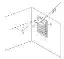
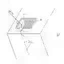
FIG. 1 shows one possible embodiment of the light shelf system
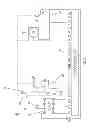
FIG. 2 shows an electrical schematic of one embodiment that has three light sensors, a clock, and an override switch.
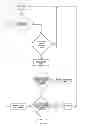
FIG. 3 shows an embodiment of a flow diagram for the microcontroller sequence of operations.
The sequence listing shows one embodiment of a program for the microcontroller to run the system using PBASIC programming language. A portion of this particular embodiment uses a segment of code from the Parallax Corporation for use with their DS1302 clock component module.
| Drawings-Reference Numerals |
| 10 light shelf | 12 light sensors | |
| 14 clock | 16 timing crystal | |
| 18 servomotor | 20 hinge | |
| 22 power source | 24 microcontroller | |
| 26 resistor | 26 phototransistor | |
| 28 capacitor | 30 window assembly | |
| 32 switch | ||
DETAILED DESCRIPTION
FIGS. 1,2, and 3
One embodiment of the apparatus is illustrated in FIG. 1. A light shelf 10 is mounted to the window assembly 30 so that light is reflected off the light shelf 10 into the adjacent space. In the embodiment shown, a plurality of light sensors 12 are placed in an orientation in the same direction at which the light shelf 12 juts into the space. A servomotor 18 is attached to the hinge 20 of the light shelf 12.
FIG. 2 shows an electrical schematic of one embodiment. The microcontroller 24 contains 16 pin locations labeled P0-P15. Other embodiments can be arranged with different configurations and the pin connections in this particular embodiment are arbitrary. As such, other embodiments can use alternate component arrangements.
A clock 14 utilizes P0, P1, and P2 for operation. The clock 14 is attached to a timing crystal 16 to keep proper time after the initial time parameters are programmed. P3, P4, and PS are each connected to the light sensors 12 in series with a resistor 26. In this embodiment, light sensors 12 comprise of a phototransistor 34 connected in parallel to a capacitor 36. However, other embodiments can use other means of light sensing and measurement. The microcontroller 24 is also connected to the servomotor 18 which drives the hinge 20 of the light shelf in this embodiment, facilitating rotation of the light shelf 10 about the axis of the hinge 20. A switch 32 is connected to the microcontroller 24 which allows for user override functionality in this embodiment. A power source 22 is connected to the microcontroller 24 to facilitate operation.
ADDITIONAL EMBODIMENTS
There are a number of alternate arrangements of light sensors 12 that would be capable of performing the necessary light differential readings. Other embodiments could use ambient sensors to determine operational times, either in lieu or in conjunction with the clock 14. Some embodiments may omit the clock 14 altogether, depended on the desired operation. It may be desirable to have an embodiment with an alarm function to denote when the system is not operating in the most advantageous manner. Other embodiments are capable of performing the same necessary functions of the basic system operation.
Operation—FIGS. 1, 2, and 3
The operation of the automatically adjusting light shelf begins with the appropriate time being programmed into the microcontroller 24. After this point, the clock 14 will automatically track the current time and continuously update. Once the system has determined that the current time is within the desired operational time periods, it will measure the light levels being reflected off of the light shelf 10 onto the light sensors 12.
Most embodiments will have a predetermined light sensor 12 placed in a location that optimizes the light within the space. It may be in the center of the room to maximize the light throughout the area or it may be placed strategically over an area that needs additional task lighting. The microcontroller 24 will measure the light levels on the individual light sensors 12 and determine which way the servomotor 18 should rotate in order optimize the desired lighting characteristics. As the servomotor 18 rotates, it causes the light shelf 10 to adjust about its hinge 20 that then optimizes the way that the light is reflected into the space. The light shelf 10 will continue to operate in this manner, measuring light levels and adjusting the reflected light at predetermined intervals until the time registered is no longer within the desired operating time periods.
ADVANTAGES
From the description above, a number of advantages from one or more aspects of various embodiments of the photoresponsive automatic solar panel cleaner become evident:
(a) The light shelf has a hinge assembly that allows it to be rotated to the most advantageous orientation for use.
(b) The use of measuring different intensities of incident light striking the light sensing elements in the embodiment allows the light shelf to be placed in a quantifiably optimized orientation.
(c) The use of a microcontroller, in conjunction with a servomotor and light sensing elements allows for the position of the light shelf to be adjusted continuously without direct user interface.
(d) The availability of a switch override in this embodiment allows for the user to manually adjust the light shelf position in the event that the desired position differs from the programmed optimized location.
(e) The use of a clock within this embodiment allows for the operational times to be optimized so that the light shelf does not operate unnecessarily during times when additional light is not needed, thus saving energy.
The embodiment in FIG. 2 shows each of the light sensors as a resistive-capacity circuit, the clock assembly, and the servomotor assembly. The sequence listing shows an embodiment of a program written in PBASIC that uses a table lookup function in conjunction with the clock to cause the light shelf to operate only during the times between sunrise and sunset, so as to avoid operation due to night lighting. Algorithms could alternatively be programmed for different operational time schemes, such as only operating during specified work schedules of the occupants.
CONCLUSIONS, RAMIFICATIONS, AND SCOPE
Accordingly, the reader will see that the automatically adjusting light shelf can be used as a means to optimize the natural daylighting within a space, leading to increased occupant comfort and productivity as well as decreased energy usage. Using light sensors to detect the current lighting conditions, the differential light measurements between the light sensors is used to determine the best orientation of the light shelf, which is rotated about a hinge to place the daylighting where it is most needed within the space.
Although the description above contains specific descriptions, these should not be interpreted as limiting the scope of the embodiments but merely as a way of providing illustrations of possible embodiments. For example, more than three light sensors can be used, or alternate methods of light sensing can be employed. Thus the scope of the embodiments should be determined by the appended claims and their appropriate legal equivalents, rather than the specific representations previously defined. The following is one embodiment of a control sequence written in PBASIC language.
| 1 | ′ {$STAMP BS2} |
| 2 | ′ {$PBASIC 2.5} | ||
| 3 | |||
| 4 | time1 | VAR | Word |
| 5 | time2 | VAR | Word |
| 6 | time3 | VAR | Word |
| 7 | Light_Threshold | CON | 20000 |
| 8 | Diff1 | VAR | Word | ′measures different light |
| 9 | {acute over ( )}levels between center and | |||
| 10 | {acute over ( )}right sensor | |||
| 11 | Diff2 | VAR | Word | ′measures different light |
| 12 | {acute over ( )}levels between center and | |||
| 13 | {acute over ( )}left sensor | |||
| 14 | position | VAR | Word | |
| 15 | counter | VAR | Word | |
| 16 | time_limit | CON | 10 | ′sets length of time between |
| 17 | {acute over ( )}cycles in minutes | |||
| 18 | Sunrise | VAR | Word | |
| 19 | Sunset | VAR | Word | |
| 20 | Time | VAR | Word |
| 21 | ′Define I/O pins and RTC variables |
| 22 | Clk CON 0 |
| 23 | Dta CON 1 |
| 24 | RTCCS CON 2 |
| 25 | RTCCmd VAR Byte |
| 26 | Value VAR Byte |
| 27 | Seconds VAR Byte |
| 28 | Minutes VAR Byte |
| 29 | Hours VAR Byte |
| 30 | Date VAR Byte |
| 31 | Month VAR Byte |
| 32 | Day VAR Byte |
| 33 | Year VAR Byte |
| 34 | Idx VAR Byte |
| 35 | ′Define RTC Command Constants |
| 36 | SecReg CON %00000 |
| 37 | MinReg CON %00001 |
| 38 | HrsReg CON %00010 |
| 39 | DateReg CON %00011 |
| 40 | MonReg CON %00100 |
| 41 | DayReg CON %00101 |
| 42 | YrReg CON %00110 |
| 43 | CtrlReg CON %00111 |
| 44 | TChgReg CON %01000 |
| 45 | BrstReg CON %11111 |
| 46 | ′Define Days-Of-Week, Months and AM/PM text. |
| 47 | ′All text is stored in EEPROM with a binary 0 |
| 48 | ′as the ENd-of-text character |
| 49 | Sun DATA “Sun”,0 |
| 50 | Mon DATA “Mon”,0 |
| 51 | Tue DATA “Tues”,0 |
| 52 | Wed DATA “Wednes”,0 |
| 53 | Thu DATA “Thurs”,0 |
| 54 | Fri DATA “Fri”,0 |
| 55 | Sat DATA “Satur”,0 |
| 56 | Jan DATA “January”,0 |
| 57 | Feb DATA “February”,0 |
| 58 | Mar DATA “March”,0 |
| 59 | Apr DATA “April”,0 |
| 60 | May DATA “May”,0 |
| 61 | Jun DATA “June”,0 |
| 62 | Jul DATA “July”,0 |
| 63 | Aug DATA “August”,0 |
| 64 | Sep DATA “September”,0 |
| 65 | Oct DATA “October”,0 |
| 66 | Nov DATA “November”,0 |
| 67 | Dcm DATA “December”,0 |
| 68 | AM DATA “ AM”,0 |
| 69 | PM DATA “ PM”,0 |
| 70 | ′Set I/O pin states and directions |
| 71 | OUTS = %0000000000000000 ′All logic low |
| 72 | DIRS = %0000000000000111 ′I/O 0,1 and 2 are output, rest are input |
| 73 | Initialize: |
| 74 | ′NOTE: Date must be set only once for every power-up of DS1302 chip. |
| 75 | Day = $01 ′Sunday |
| 76 | Month = $01 ′January |
| 77 | Date = $28 ′28th |
| 78 | Year = $12 ′2012 |
| 79 | Hours = $12 ′12:00 PM (in 24-hour mode) |
| 80 | Minutes = $30 |
| 81 | Seconds = $00 |
| 82 | GOSUB SetTimeAndDate |
| 83 | |
| 84 | ′***intitialize servo**** |
| 85 | position = 500 |
| 86 | |
| 87 | DO UNTIL IN15 = 1 |
| 88 | GOSUB ReadRTCBurst |
| 89 | GOSUB GetSunriseSunset |
| 90 | GOSUB PrintLongDate |
| 91 | Time = (100*((Hours>>4)*10+(Hours & $oF))) |
| 92 | + ((Minutes>>4)*10+(minutes & $0F) | {acute over ( )}converts HEX time into DEC |
| 93 | {acute over ( )}GOSUB Print24HourTime | |
| 94 | counter = 0 |
| 95 | IF Time > Sunrise AND Time < Sunset THEN GOSUB Measure_Light |
| 96 | ′measure light intensity on | |
| 97 | {acute over ( )}each sensor | |
| 98 | GOSUB Adjust_Shelf | ′adusts light shelf if center |
| 99 | {acute over ( )}sensor | |
| 100 | ′is not receiving the most | |
| 101 | {acute over ( )}light | |
| 102 | DO | |
| 103 | PAUSE 60000 | ′each pause session is one min |
| 104 | counter = counter + 1 |
| 105 | LOOP UNTIL counter = time_limit | ′pause until the number of |
| 106 | {acute over ( )}minutes | |
| 107 | ′between of time shelf cycles | |
| 108 | {acute over ( )}is met | |
| 109 | LOOP | |
| 110 | ||
| 111 | Measure_Light: | |
| 112 | ||
| 113 | HIGH 4 | |
| 114 | PAUSE 3 | ′measures left sensor |
| 115 | RCTIME 4,1,time1 | |
| 116 | PAUSE 1000 | |
| 117 | ||
| 118 | HIGH 5 | ′measures center sensor |
| 119 | PAUSE 3 | |
| 120 | RCTIME 5,1,time2 | |
| 121 | PAUSE 1000 | |
| 122 | ||
| 123 | HIGH 6 | ′measures right sensor |
| 124 | PAUSE 3 | |
| 125 | RCTIME 6,1,time3 | |
| 126 | PAUSE 1000 | |
| 127 | ||
| 128 | Diff1 = time2 − time1 | ′measure difference between |
| 129 | ′center and left sensor | |
| 130 | Diff2 = time2 − time3 | ′measure difference between |
| 131 | ′center and right sensor | |
| 132 | IF Diff1 > Light_Threshold THEN | ′Compensates for negative |
| 133 | difference | |
| 134 | Diff1 = 0 | ′between sensor comparison |
| 135 | ENDIF | |
| 136 | IF Diff2 > Light_Threshold THEN | |
| 137 | Diff2 = 0 | |
| 138 | ENDIF | |
| 139 | ||
| 140 | RETURN | |
| 141 | ||
| 142 | Adjust_Shelf: | |
| 143 | ′if right sensor receives | |
| 144 | ′more light than center | |
| 145 | {acute over ( )}sensor rotate shelf CW | |
| 146 | IF Diff1 > Diff2 THEN |
| 147 | IF Diff1 >= 20 THEN position = position + 5 |
| 148 |
| 149 | ′if left sensor receives | |
| 150 | ′more light than center | |
| 151 | {acute over ( )}sensor rotate shelf CCW |
| 152 | ELSEIF Diff2 > Diff1 THEN |
| 153 | IF Diff2 >= 20 THEN position = position − 5 |
| 154 | ENDIF |
| 155 | PULSOUT 14, position |
| 156 | RETURN |
| 157 | ′==================== DS1302 Real-Time Clock Subroutines |
| 158 | PrintLongDate: |
| 159 | ′Print long date format on debug screen |
| 160 | LOOKUP Day-1,[Sun,Mon,Tue,Wed,Thu,Fri,Sat],Idx |
| 161 | GOSUB PrintIt |
| 162 | LOOKUP Month-1,[Jan,Feb,Mar,Apr,May,Jun,Jul,Aug,Sep,Oct,Nov,Dcm],Idx |
| 163 | GOSUB PrintIt |
| 164 | ′NOTE: The following line prints the proper 4-digit year for the years |
| 165 | ′1990 through 2089 |
| 166 | RETURN |
| 167 | |
| 168 | PrintShortDate: |
| 169 | ′Print short date format on debug screen |
| 170 | RETURN |
| 171 | Print12HourTime: |
| 172 | ′Print 12-hour time format on debug screen |
| 173 | ′NOTE: The DS1302 has 12 and 24 hour time-keeping modes (bit 7 of |
| 174 | HrsReg |
| 175 | ′sets 12/24 mode and bit 5 indicates AM/PM or 20+ hours). For purposes |
| 176 | ′of this example, we're using 24 hour mode only, and converting it to |
| 177 | ′12-hour in the next two lines below. |
| 178 | DEBUG DEC2 12-(24-(Hours.HIGHNIB*10+Hours.LOWNIB)//12),“:”,HEX2 |
| 179 | Minutes,“:”,HEX2 Seconds,CR |
| 180 | LOOKUP Hours/$12,[AM,PM],Idx |
| 181 | GOSUB PrintIt |
| 182 | ′GOSUB GetSunriseSunset |
| 183 | ′DEBUG ? Sunrise, CR |
| 184 | ′DEBUG ? Sunset, CR |
| 185 | RETURN |
| 186 | |
| 187 | Print24HourTime: |
| 188 | ′Print 24-hour time format on debug screen |
| 189 | ′for checking set time |
| 190 | DEBUG HEX2 Hours,“:”,HEX2 Minutes,“:”,HEX2 Seconds, CR |
| 191 | RETURN |
| 192 | |
| 193 | PrintIt: |
| 194 | ′Prints zero (0) terminated text from EEPROM |
| 195 | READ Idx,Value ′Get next character |
| 196 | IF Value = 0 THEN Finished ′Make sure it's not a binary 0 |
| 197 | DEBUG Value ′Display it on screen |
| 198 | Idx = Idx + 1 |
| 199 | GOTO PrintIt |
| 200 | Finished: |
| 201 | RETURN |
| 202 | |
| 203 | WriteRTCRAM: |
| 204 | ′Write to DS1302 RAM Register |
| 205 | HIGH RTCCS |
| 206 | SHIFTOUT Dta, Clk, LSBFIRST, [%0\1,RTCCmd\5,%11\2,Value] |
| 207 | LOW RTCCS |
| 208 | RETURN |
| 209 | |
| 210 | WriteRTC: |
| 211 | ′Write to DS1302 |
| 212 | HIGH RTCCS |
| 213 | SHIFTOUT Dta, Clk, LSBFIRST, [%0\1,RTCCmd\5,%10\2,Value] |
| 214 | LOW RTCCS |
| 215 | RETURN |
| 216 | |
| 217 | ReadRTCBurst: |
| 218 | ′Read all time-keeping registers in one burst |
| 219 | HIGH RTCCS |
| 220 | SHIFTOUT DTA, Clk, LSBFIRST, [%1\1,BrstReg\5,%10\2] |
| 221 | SHIFTIN DTA, Clk, LSBPRE, [Seconds,Minutes,Hours,Date,Month,Day,Year] |
| 222 | LOW RTCCS |
| 223 | RETURN |
| 224 | |
| 225 | ReadRTCRAM: |
| 226 | ′Read DS1302 RAM Register |
| 227 | HIGH RTCCS |
| 228 | SHIFTOUT DTA, Clk, LSBFIRST, [%1\1,RTCCmd\5,%11\2] |
| 229 | SHIFTIN DTA, Clk, LSBPRE, [Value] |
| 230 | LOW RTCCS |
| 231 | RETURN |
| 232 | SetTimeAndDate: |
| 233 | ′Write time values into all time-keeping registers, being sure to clear |
| 234 | ′the write-protect bit in CtrlReg before the write, and set the |
| 235 | ′write-protect bit after the write |
| 236 | FOR Idx = 0 TO 8 |
| 237 | LOOKUP Idx,[0,Seconds,Minutes,Hours,Date,Month,Day,Year,128],Value |
| 238 | LOOKUP Idx,[CtrlReg, SecReg, MinReg, HrsReg, DateReg, MonReg, DayReg, |
| 239 | YrReg, CtrlReg],RTCCmd |
| 240 | GOSUB WriteRTC |
| 241 | NEXT |
| 242 | RETURN |
| 243 | ′*********************SETTING SUNSET/SUNRISE************************** |
| 244 | GetSunriseSunset: |
| 245 | ′Converts HEX Year into Decimal form and looks up relevant months for |
| 246 | {acute over ( )}2012 |
| 247 | IF (year>>4)*10 + (year & $0F) = 12 THEN |
| 248 | ′Converts HEX Month into decimal and checks if it is January |
| 249 | IF (Month>>4)*10 + (Month & $0F) = 01 THEN |
| 250 | ′looks up sunrise times for January dates and assigns value |
| 251 | LOOKUP (Date>>4)*10 + (Date & $0F), [0804, 0804, 0804, 0804, 0804, |
| 252 | 0804, 0804, 0804, 0803, 0803, 0803, 0803, 0802, 0802, 0802, 0801, 0801, |
| 253 | 0800, 0759, 0759, 0758, 0758, 0757, 0756, 0755, 0754, |
| 254 | 0754, 0753, 0752, 0751, 0750], Sunrise |
| 255 | ′allows the Measure_Light subroutine to occur no earlier than 2 hours |
| 256 | before sunrise |
| 257 | sunrise = sunrise + 200 |
| 258 | ′looks up sunset times for January dates and assigns value |
| 259 | LOOKUP (Date>>4)*10 + (Date & $0F), [1713, 1714, 1715, 1716, 1717, |
| 260 | 1718, 1719, 1720, 1721, 1722, 1723, 1724, 1725, 1726, 1727, 1728, 1730, |
| 261 | 1731, 1732, 1733, 1735, 1736, 1737, 1738, 1740, 1741, |
| 262 | 1742, 1743, 1745, 1746, 1747], Sunset |
| 263 | ′allows the Measure_Light routine to occur no later than 2 hours before |
| 264 | sunset |
| 265 | sunset = sunset − 200 |
| 266 | ′Converts HEX Month into decimal and checks if it is February |
| 267 | ELSEIF (Month>>4)*10 + (Month & $0F) = 02 THEN |
| 268 | ′looks up sunrise times for February dates and assigns values |
| 269 | LOOKUP (Date>>4)*10 + (Date & $0F), |
| 270 | [0749,0748,0747,0746,0745,0743,0742,0741,0740,0739,0737,0736,0735,0733, |
| 271 | 0732,0731,0729, |
| 272 | 0728,0726,0725,0723,0722,0720,0719,0717,0716,0714,0713,0711], Sunrise |
| 273 | ′looks up sunset times for February dates and assigns values |
| 274 | LOOKUP (Date>>4)*10 + (Date & $0F), |
| 275 | [1749,1750,1751,1753,1754,1755,1756,1758,1759,1800,1802,1803,1804,1805, |
| 276 | 1807,1808,1809,1811, |
| 277 | 1812,1813,1814,1816,1817,1818,1819,1821,1822,1823,1824], Sunset |
| 278 | ENDIF |
| 279 | ENDIF |
| 280 | RETURN |
| 281 | ′ELSEIF Year = 13 THEN | ///For brevity's sake, the additional years |
| 282 | {acute over ( )}have been omitted. | |
| 283 | ′IF Month = Jan | ///Full version has all months of all |
| 284 | {acute over ( )}years up to 2086 for DS1302 clock | |
| 285 | ′LOOKUP Date | |
| 286 | ′endif | |
| 287 | ′ENDIF | |
Claims
What is claimed is:1. A machine, comprising:
a. An automatic circuit of components capable of determining the lighting conditions within a space;
b. A light shelf or similar reflective surface;
c. A device capable of automatically orienting the light shelf or reflective surface, whereas the altered orientation affects the light entering the space.
2. The automatic circuit claimed in claim 1 wherein the light levels are measured by a plurality of photoresponsive elements capable of detecting the incident light levels reaching a particular area within said space.
3. The photoresponsive elements claimed in claim 2, wherein said photoresponsive elements comprise of:
a. A capacitive component;
b. A phototransistor in parallel with said capacitive component wherein different light levels reaching said photoresponsive elements results in measurable differences in the resistive-capacitive time constant of said photoresponsive element.
4. The automatic circuit as claimed in claim 1 wherein the device that provides capability of reorienting said light shelf is an actuated servomotor.
5. The automatic circuit as claimed in claim 1 wherein a manually operated switch is capable of overriding the automatic operation.
6. The automatic circuit as claimed in claim 1 that has a clock signal generator to be referenced for system operations.
7. A method for automatically adjusting the light shelf, comprising:
a. A measured differential between the incident light reaching the light sensors within the space;
b. Providing a means to reorient said light shelf so that the reflected light is optimized for a desired outcome.
8. The method for automatically adjusting the light shelf as claimed in claim 7, wherein the method further comprises:
a. Providing an operational time controller;
b. Providing a regularly updated time reading;
c. Referencing said time against the desired operating time parameters;
d. Operating the reorientation of said light shelf only if the updated time is within the designed operational time parameters.
Images & Drawings included:
Sources:
- United States Patent and Trademark Office - verify current appl. status at the USPTO↗
Recent applications in this class:
- » 20130214122 2013-08-22
Method and apparatus for using gestures to control a laser tracker - » 20130037694 2013-02-14
Method and apparatus for using gestures to control a laser tracker - » 20130010308 2013-01-10
Method and apparatus for using gestures to control a laser tracker - » 20130009035 2013-01-10
Method and apparatus for using gestures to control a laser tracker - » 20120305747 2012-12-06
Omnidirectional sun position sensing device with a plurality of optical sensors - » 20110260033 2011-10-27
Method and apparatus for using gestures to control a laser tracker - » 20100321199 2010-12-23
Light-emitting module and image-capturing module for arbitrarily changing light-emitting position - » 20090272877 2009-11-05
Method and apparatus of measuring backward light, and laser processing method - » 20090050191 2009-02-26
System and Method for Solar Tracking - » 14068993 2016-05-03
Target feature integrated laser phase compensation system